
Related Manuals for Pylontech PowerCube-M2


Summary of Contents for Pylontech PowerCube-M2
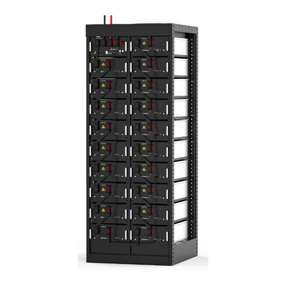
- Page 1 LFP Lithium Ion Energy Storage System PowerCube-M2 Operation Manual Information Version: EU20PM2B1001 AS0MM2A18011...
-
Page 3: Table Of Contents
This manual introduces PowerCube-M2 from Pylontech. PowerCube-M2 is a high voltage Lithium-Ion Phosphate Battery storage system. Please read this manual before you install the battery and follow the instruction carefully during the installation process. Any confusion, please contact Pylontech immediately for advice and clarification. - Page 4 3.3.6 Grounding System .......................18 3.4 Package Items .........................18 3.5 Handling and placement .....................22 3.5.1 Handling and placement of the battery module ..........22 3.5.2 Handling and placement of the rack ..............22 3.5.3 The fix and installation of the rack ................22 3.5.4 Control Module (BMS) and all Battery Modules install into the Rack ....22 3.5.5 Install the MBMS into a 19’...
- Page 5 5.1 Trouble Shooting: ......................38 5.2 Replacement of main component ................40 5.2.1 Replacement of Battery Module ................40 5.2.2 Replacement of Control Module (BMS) ..............42 5.2.3 Replacement of 3 level Control Module (MBMS) ..........42 5.3 Battery Maintenance .....................43 STORAGE RECOMMENDATIONS..................... 45 SHIPMENT ............................45 ANNEX 1: CAN COMMUNICATION BETWEEN MBMS AND BMS CABLE DIAGRAM: (≤6SET) ....
-
Page 6: Safety
Safety The PowerCube-M2 is a high voltage DC system, operated by authorized person only. Read all safety instructions carefully prior to any work and observe them at all times when working on with the system. Incorrect operation or work may cause: injury or death to the operator or a third party;... - Page 7 Caution Risk of battery system failure or life cycle reduces. Symbol Read the product and operation manual before operating the in label battery system! Symbol Danger! Safety! in label Symbol Warning electric shock! in label Symbol Do not place near flammable material in label Symbol Do not reverse connection the positive and negative.
- Page 8 Warning: Whenever working on the battery, wear suitable personal protective equipment (PPE) such as rubber gloves, rubber boots and goggles. Warning: PowerCube-M2 system working temperature range: 10℃~40℃; Optimum temperature: 18℃~28℃. Out of the working temperature range may cause the battery system over / low temperature alarm or protection which further lead to the...
-
Page 9: Reference Standards
Caution: Improper settings or maintenance can permanently damage the battery. Caution: Incorrect inverter parameters will lead to the premature aging of battery. 1.2 Reference standards Description Code Safety standard for IEC62619 secondary lithium batteries UN38.3 Safe transport UN38.3 standard EN IEC 61000-6-1:2019 EN IEC 61000-6-2:2019 EN 61000-6-3:2007+A1 CE EMC Standard... -
Page 10: System Introduce
Pylontech, it can be used to support reliable power for various types of equipment and systems. PowerCube-M2 is especially suitable for application scene of high power, limited installation space, restricted load- bearing and long cycle life. - Page 11 5 – 95%(without condensing) Humidity Round-trip efficiency(@1C-rate) Depth of Discharge Dimension 803mm(W)*845mm(D)*2130mm(H) Single Rack: 140+ 55×n Weight (where n = 1~19) kg Operation cycle life >5,000 Opertion Life(Years) IP rating IP20 Cooling type Natural Cooling Altitude [m] <4,000 Certification IEC62619, CE EMC, UN38.3...
- Page 12 Battery Module (HM2A180) 2.2.2 Product Type HM2A180 Cell Technology Li-ion(LFP) Battery Module Capacity (kWh) 5.6832 Battery Module Voltage (Vdc) 38.4 Battery Module Capacity (AH) Dimension(W*D*H, mm) 315×820×171.5 Protection Class IP20 Weight (kG) Operation Cycle Life 5,000 0~50℃ Operation Temperature -20~60℃ Storage Temperature Transfer Certificate UN38.3...
- Page 13 Status ● ● Status light: to show the battery module’s status ( Normal Abnormal RS232 Terminal Console Communication Terminal: (RJ45 port) follow RS232 protocol, for manufacturer or professional engineer to debug or service. Link Port 0, 1 Link Port 0, 1 Communication Terminal: (RJ45 port), CAN communication , between multiple serial battery modules and control module.
-
Page 14: Control Module
2.2.2 Control Module PowerCube-M2’s Control Module has two version, with external(S1000M2A180) or internal (S1000M2A180J) power supply. Product Type S1000M2A180 S1000M2A180J Related Product M2-180 M2-180 AC Supply 100 - 290Vac/50Hz/1.3A System Operation Voltage(Vdc) 0~1000 0~1000 Operation Current(Max.)(A) Self-consumption Power(W) Dimension(W*D*H,mm) 315×710×171.5 315×738×171.5... - Page 15 Control Module (S1000M2A180J) Front Interface External Power Terminal D+/D- Connect battery system with Inverter. Power Terminal B+/B- To connect battery power cables in series. 12VDC In / Out In: For input 12Vdc/10Amps to power supply the BMS separately. OUT: Power supply for MBMS, to connect with MBMS’ 12VDC IN. AC Input AC Socket and Control Module Power Switch: External power supply Control Module has an Australia or Europe standard AC Power input socket and power switch.
- Page 16 Europe Standard Caution: It shall be installed an AC breaker outside for AC short-circuit protection. The specifications of the breaker shall meet the system's parameters. System parameters refer to the system parameters table (chapter 2.2.1) Dry Contact Terminal Dry Contact Terminal: provided 2 input and 4 output dry contact signal. Reset Reset Button: Long press this button to restart the battery system.
- Page 17 RS485 Communication Terminal: (RJ45 port) follow Modbus RTU/TCP/IP protocol, for communication between battery system and inverter. RS232 Terminal Console Communication Terminal: (RJ45 port) follow RS232 protocol, for manufacturer or professional engineer to debug or service. LAN Terminal Console Communication Terminal: (RJ45 port) follow Modbus 485 protocol, used for communication between BMS and switches.
- Page 18 LED Indicators Instructions STATUS STATUS Protection / Capacity SOC Descriptions Battery (green) (red) Alarm / Status ● ● ● ● ● ● Normal Shut Down All off Indicates Sleep Mode, to Sleep Normal Flash2 save the power. Indicates save power Normal Light mode.
-
Page 19: System Diagram
2.3 System Diagram 2.3.1 Multiple battery string parallel connection by CAN communication between MBMS and BMS diagram (battery string qty. ≤6) 2.3.1.1 External power supply block 2.3.1.2 Internal power supply block 2.3.2 Multi battery string parallel connection by Ethernet communication between MBMS and BMS diagram (battery string qty. -
Page 20: Diagram Between Bms And Battery Modules
2.3.3 Diagram between BMS and battery modules: 2.3.3.1 External power supply block 2.3.3.2 Internal power supply block... -
Page 21: Installation
Installation Please check every installation step with <Annex 2: Installation and System Turn ON Progress List> during the install. 3.1 Tools The following tools are required to install the battery pack: Wire Cutter Crimping Modular Plier Cable Ties Screw Driver Set Electric Screw Driver Insulating Gloves Adjustable Wrench... -
Page 22: Safety Gear
(battery module can’t be turned off), must be careful to handle the Power Plugs. 3.3.2 Temperature PowerCube-M2 system working temperature range: 10℃~40℃; Optimum temperature: 18℃~ 28℃. Caution: Out of the working temperature range may cause the battery reduces the cycle of life even cause the battery system over / low temperature alarm or protection. -
Page 23: Heating System
Caution: Out of the working temperature range may cause the battery reduces the cycle of life even cause the battery system over / low temperature alarm or protection. 3.3.4 Heating System The room must be equipped with heating system. If the environment is lower than 0℃, must turn on the heating system at first. - Page 24 The ring terminals (M8 screw) use 13mm sleeve. Unpacking and check the Packing List: Internal Cable Kits for wiring connection up to Battery Controller Power Copper Bar - Battery Black/209*28*20*3mm/Soft Copper 1pcs Module and Main Controller - Bar/Ø 9 Ring Type Terminals Power Cable (Battery Module Black/209*133*20*3mm/Soft Upper and Lower Serial...
- Page 25 Orange/370*135*20*3mm/Soft Power Copper Bar - Battery Copper Bar/Ø 9 Ring Type 1pcs Module and Main Controller + Terminals Battery Cascade Black/0.18m/8 Core Super 5th 1pcs Communication Cable (0.18m) Class Twisted-pair Wire/RJ45 Battery Cascade Black/0.5m/8 Core Super 5th Class 1pcs Communication Cable (0.5m) Twisted-pair Wire/RJ45...
- Page 26 External Cable Kits for wiring connection from Battery Controller to PCS/EMS/Power Supply External Battery CAN Black/5m/Super 5th Class Twisted- 1pcs Communication Cable (direct) pair Wire/2 RJ45 terminal Orange/5m/1/0AWG/SURLOK External Power Cable + 1pcs Terminal/50-8 Terminal Black/5m/1/0AWG/SURLOK External Power Cable - 1pcs Terminal/50-8 Terminal For external power supply control module there is additional AC power cable:...
-
Page 27: Handling And Placement
3.5 Handling and placement Warning: The battery rack is IP00. It must be installed in a restricted access area; Warning: The PowerCube-M2 is a high voltage DC system, operated by qualified and authorized person only. 3.5.1 Handling and placement of the battery module Single battery module is 55kg. -
Page 28: Install The Mbms Into A 19' Standard Rack [If Configured]
Install the control module (BMS) and all battery modules in. Each module uses 4 screws to fix 3.5.5 Install the MBMS into a 19’ standard rack [If configured] Install the buckle nuts. The position of nuts must meet the position of the MBMS. ... -
Page 29: Cables Connection
The PowerCube-M2 modules’ grounding is based on metal directly touch between the module’s surface and rack’s surface. So it needn’t grounding cables at all. If uses normal rack, remove the paint at the corresponding place. Rack Grounding: If there is a grounding metal frame outside the rack, for example, the metal angle steel frame at the bottom of the container, the fix hole of the fix frame can be fixed directly with the metal frame of the container. -
Page 30: Can Communication Mode Between Mbms And Bms (Battery String Qty. ≤6 Set) (Battery String Qty. ≤6 Set)
3.6.2.1 CAN Communication Mode between MBMS and BMS (battery string qty. ≤6 set) (battery string qty. ≤6 set) When system configured PowerCube-M2 ≤6 set. The communication between PowerCube-M2 uses CAN communication mode. The communication between the MBMS and the BMS of 1... - Page 31 Note: The 1 PowerCube-M2 should be installed nearest by the MBMS.
-
Page 32: Ethernet Communication Between Mbms And Bms (Battery String Qty ≥7 Set)
3.6.2.2 Ethernet communication between MBMS and BMS (battery string qty ≥7 set) A. When system configured PowerCube-M2 ≥7 set. The communication between PowerCube- M2s and MBMS uses Ethernet Switch by LAN communication. -
Page 33: Add Switch Setting (Address Assignment)
The last port of Ethernet Switch is for the MBMS. From the 1 port to the n port are for the corresponding battery string (PowerCube-M2). 3.6.3 ADD Switch Setting (Address Assignment) ADD Switch - Battery Controller is a 6 bit dial switches to manually distribute the communication address of the battery system. -
Page 34: Under Ethernet Communication Between Mbms And Bms (Battery String Qty. 1~32 Set)
The address is configured follow ASCII code: (“X” is terminal resistance). BMS’s Address Configure Table: The MBMS’s ADD Switch set with “000011”. The last 2 bits are terminal resistances. Note: the 1 to 4 bit dial for MBMS refer to 3.6.3.4. 3.6.3.3 Under Ethernet communication between MBMS and BMS (battery string qty. -
Page 35: System Turns On
3.6.4 System turns on Double check all the power cables and communication cables. Make sure the voltage of the PCS is same level with the battery system. Check all the power switch of every battery system is OFF. Warning: MBMS must be turned on AFTER all battery strings self-check finish. (1) Check the UPS(if has) is turned on. - Page 36 For external power supply, 1. Turn on the “Power Switch”: 2. Turn on the “POWER OUTPUT SWITCH”: Caution: When the breaker is tripped off because the system has over current or short circuit, must after 30min to turn on it again, otherwise may cause the breaker damage.
- Page 37 Status LED on BMS/battery all in green - If the BMS and all battery modules are working normally, every status LED will lighting green, that’s mean self-check are pass. Self-check will be finish within 5sec. Status LED on BMS switch to red after 30sec - The BMS can’t receive communication from upper equipment because the communication is off, the “STATUS”...
- Page 38 system will entering into self-check mode automatically. If the BMS and all battery modules are working normally, every status LED will be lighting green, that’s mean self-check are pass. Self-check will be finish within 10sec. Black-start function: If long press(>10sec) the start button 30s AFTER power on. The“STATUS” lamp will becomes green if the black start function is enabled.
-
Page 39: System Turns Off
During maintenance or long term storage, must turn off the battery system: For external power supply, (1) Turn off the switch between PCS and this battery string (PowerCube-M2), or turn off the power switch of PCS, to make sure no current through this battery string. - Page 40 (5) Turn off the UPS(if has). The UPS can turn on if have equipment must keep running can’t turn off. Otherwise must turn off the UPS to save its power. Caution: Before change the battery module for service, must charge/discharge the replaced battery same voltage to the other in system battery modules.
- Page 41 (1) Turn off the switch between PCS and this battery string (PowerCube-M2), or turn off the power switch of PCS, to make sure no current through this battery string. (2) Turn off the “Isolating Switch” of the BMS. (3) Turn off the “Power Switch” of the MBMS. If the ESS configures only single battery without MBMS, so needn’t this operation step.
-
Page 42: System Debug
System Debug This system debug is for BESS system (Battery Energy Storage System). BESS system can’t do the debug alone. It must operation with configured UPS, PCS and EMS system together. Debug Step Content Prepare of debug. Turn on the BESS system, refer to chapter 3. Before turn on the whole BESS system turn on the load is not allowed! Remark: Except the BESS, if other equipments have its own system turn on step, must follow its own system operation menu. -
Page 43: Maintenance
Maintenance 5.1 Trouble Shooting: Danger: The PowerCube-M2 is a high voltage DC system, operated by qualified and authorized person only. Danger: Before check the failure, must check all the cables connection and setting of ADD Switches are right or not (refer to chapter 3), and the BESS system can turn on normally or not. - Page 44 are fine or not. Turn on the BMS power DC Output breaker is fault. Check output Switch. The Status LED shows breaker is fault or not. If it is OK. But can’t output power. fault, change the control module (BMS module). Turn on and turn off the “POWER OUTPUT”...
-
Page 45: Replacement Of Main Component
5.2 Replacement of main component Danger: The PowerCube-M2 is a high voltage DC system, operated by qualified and authorized person only. Danger: Before replace the main component must shut off the maintenance battery string’s power. Must confirm the D+ and D- terminal are without power. The turn off progress refer to chapter 3.6.5. - Page 46 5.2.1.1 Make sure the new battery module has an equivalent voltage level (OCV) compare to existing modules. 5.2.1.2 Shut off the whole battery string’s power. Must confirm the D+ and D- terminal are without power. The turn off progress refer to chapter 3.6.5. 5.2.1.3 Pull out the Plug of Power Cable +/-.
-
Page 47: Replacement Of Control Module (Bms)
5.2.1.8 Make a fully charge of the system before normal operation. 5.2.2 Replacement of Control Module (BMS) 5.2.1.1 Shut off the whole battery string’s power. Must confirm the D+ and D- terminal are without power. The turn off progress refer to chapter 3.6.5. 5.2.2.2 Pull out the plugs of Power Cables and the communication plugs. -
Page 48: Battery Maintenance
Caution: Turn off this MBMS will stop the power output of belonging whole Battery Energy Storage System. 5.2.3.2 Dismantle the 4 screws. 5.2.3.3 Install the new MBMS inside. And reconnect the cables. Refer to chapter 3.5. 5.2.3.4 Turn on this MBMS. Refer to chapter 3.6. Caution: Before pull out the communication cables must mark the cable number, to avoid cable wrong sequence. - Page 49 5.3.3 Cables Inspection: [Periodical Maintenance] Visual inspect all the cables of battery system. Check the cables has broken, aging, getting loose or not. 5.3.4 Balancing: [Periodical Maintenance] The battery strings will become unbalance if long time not be full charged. Proposal: every 3 month should do the balancing maintenance (charge to full). 5.3.5 Output Relay Inspection: [Periodical Maintenance] Under low load condition (low current), control the output relay OFF and ON to hear the relay has click voice, that’s mean this relay can off and on normally.
-
Page 50: Storage Recommendations
Storage Recommendations For long-term storage, if stored for a long time (more than 3 months), the battery cells should be stored in the temperature range for 5~45℃, relative humidity <65% and contains no corrosive gas environment. The battery should shelfed in 5~45℃, dry, clean and well ventilated environment. Before storage the battery should be charged to 50~55% SoC;... -
Page 51: Annex 1: Can Communication Between Mbms And Bms Cable Diagram: (≤6Set)
Annex 1: CAN communication between MBMS and BMS Cable Diagram: (≤6set) -
Page 52: Annex 2: Ethernet Communication Between Mbms And Bms Cable Diagram: (>6Set)
Annex 2: Ethernet communication between MBMS and BMS Cable Diagram: (>6set) -
Page 53: Annex 3: Installation And System Turn On Progress List
Annex 3: Installation and System Turn ON Progress List Tick after Item Remark completion The environment is meeting all technical requirements. 3.3.1 Cleaning 3.3.2 Temperature Refer to chapter ☐ 3.3.3 Radiating System 3.3.4 Heating System 3.3.5 Fire-extinguisher System 3.3.6 Grounding System Battery rack installed... - Page 54 Check the UPS is turned on. And the UPS is power Refer to chapter ☐ supplying. 3.6.4. Switch the external power or PCS on, to sure all the Refer to chapter ☐ power equipment can work normally. 3.6.4. Turn the BMS (Battery Control Modules) of each battery string on (from 1 BMS to the last, one by one) Turn on the “POWER OUTPUT SWITCH”:...
-
Page 55: Annex 4: System Turn Off Progress List
Remark completion Turn off the switch between PCS and this battery string Refer to chapter ☐ (PowerCube-M2), or turn off the power switch of PCS, to 3.6.5. make sure no current through this battery string. Refer to chapter ☐ Turn off the “Power Output Switch” of the BMS. - Page 56 Pylon Technologies Co., Ltd. No. 73, Lane 887, ZuChongzhi Road, Zhangjiang Hi-Tech Park Pudong, Shanghai 201203, China T+86-21-51317699 | +86-21-51317698 service@pylontech.com.cn www.pylontech.com.cn...
Need help?
Do you have a question about the PowerCube-M2 and is the answer not in the manual?
Questions and answers