
Subscribe to Our Youtube Channel
Related Manuals for Pylontech PowerCube-M1


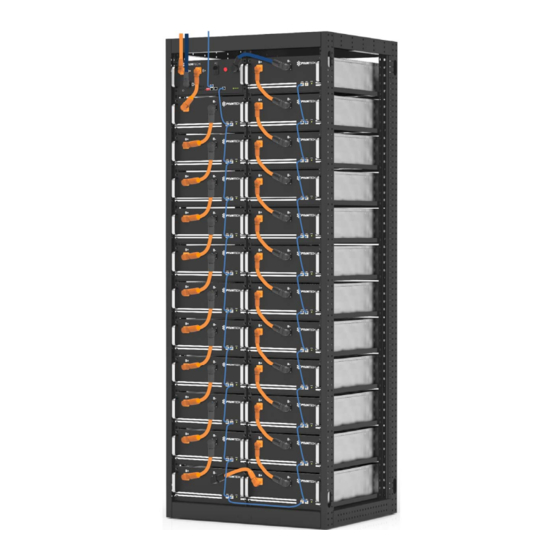
Summary of Contents for Pylontech PowerCube-M1
- Page 1 Lithium-Ion Phosphate Energy Storage System PowerCube-M1 Operation Manual Information Version: 2.2...
-
Page 2: Table Of Contents
This manual introduces PowerCube-M1 from Pylontech. PowerCube-M1 is a high voltage Lithium-Ion Phosphate Battery storage system. Please read this manual before you install the battery and follow the instruction carefully during the installation process. Any confusion, please contact Pylontech immediately for advice and clarification. - Page 3 CAN Communication Mode between MBMS and BMS Cable Diagram : ...... 12 3.6.2.2 Ethernet communication between MBMS and BMS (battery string qty. ≥ 1 set) ............................13 Ethernet communication between MBMS and BMS Cable Diagram: ......13 3.6.3 ADD Switch Setting (Address Assignment) ............... 14 3.6.3.1 Under communication for single BMS (battery string qty.
-
Page 4: Safety
Safety The PowerCube-M1 is a high voltage DC system, operated by authorized person only. Read all safety instructions carefully prior to any work and observe them at all times when working on with the system. Incorrect operation or work may cause: injury or death to the operator or a third party;... - Page 5 Warning: Whenever working on the battery, wear suitable personal protective equipment (PPE) such as rubber gloves, rubber boots and goggles. Warning: PowerCube-M1 system working temperature range: 10℃~40℃; Optimum temperature: 18℃~28℃. Out of the working temperature range may cause the battery reduces the cycle of life even cause the battery system over / low temperature alarm or protection.
-
Page 6: System Introduce
PowerCube-M1 is a high voltage battery storage system based on lithium iron phosphate battery, is one of new energy storage products developed and produced by Pylontech, it can be used to support reliable power for various types of equipment and systems. PowerCube-M1 is especially suitable for application scene of high power, limited installation space, restricted load-bearing and long cycle life. -
Page 7: System Diagram
2.2 System Diagram 2.2.1 Multi battery string parallel connection by CAN communication between MBMS and BMS diagram (battery string qty. ≤ conne 2.2.2 Multi battery string parallel connection by Ethernet communication between MBMS and BMS diagram (battery string qty. ≥1 set) 2.2.3 Diagram between BMS and battery modules: 4 / 32 19PIMV0802... -
Page 8: Installation
Installation Please check every installation step with <Annex 2: Installation and System Turn ON Progress List> during the install. 3.1 Tools The following tools are required to install the battery pack: Wire Cutter Crimping Modular Plier Cable Ties Screw Driver Set Electric Screw Driver Adjustable Wrench Sleeve Piece... -
Page 9: System Working Environments Checking
(battery module can’t be turned off), must be careful to handle the Power Plugs. 3.3.2 Temperature PowerCube-M1 system working temperature range: 10℃~40℃; Optimum temperature: 18℃~ 28℃. Caution: Out of the working temperature range may cause the battery reduces the cycle of life even cause the battery system over / low temperature alarm or protection. -
Page 10: Package Items
3.4 Package Items Accessories The type and quantity of the accessories are subject to the battery packing list. NOTE Power cable uses water-proofed connectors. It must keep pressing this Lock Button during pulling out the power plug. Unpacking and check the Packing List: Power Cable + (Battery Module Orange/0.19m/1/0AWG/2 Orange and Main Controller Serial... - Page 11 Battery Cascade Black/0.18m/8 Core Super 5th Communication Cable (0.18m) Class Twisted-pair Wire/RJ45 Battery Cascade Black/0.5m/8 Core Super 5th Class Communication Cable (0.5m) Twisted-pair Wire/RJ45 External Battery CAN Black/3.5m/Super 5th Class Communication Cable (direct) Twisted-pair Wire/2 RJ45 terminal Orange/3.5m/1/0AWG/SURLOK External Power Cable + Terminal/50-8 Terminal Black/3.5m/1/0AWG/SURLOK External Power Cable -...
-
Page 12: Handling And Placement
3.5 Handling and placement Warning: The battery rack is IP00. It must be installed in a restricted access area; Warning: The PowerCube-M1 is a high voltage DC system, operated by qualified and authorized person only. 3.5.1 Handling and placement of the battery module Single battery module is 48kg. -
Page 13: Control Module (Bms) And All Battery Modules Install Into The Rack
To the Bottom 3.5.4 Control Module (BMS) and all Battery Modules install into the Rack Dismantle the rack metal strip (on the left side and right side of the rack). After installed the control module (BMS) and all battery modules need install these two stop blend back. Install the buckle nuts. -
Page 14: Cables Connection
Caution: Wrong communication cables connection will cause the battery system failure. Grounding The PowerCube-M1 modules’ grounding is based on metal directly touch between the module’s surface and rack’s surface. So it needn’t grounding cables at all. If uses normal rack, remove the paint at the corresponding place. -
Page 15: Can Communication Mode Between Mbms And Bms
3.6.2.1 CAN Communication Mode between MBMS and BMS (battery string qty. ≤6 set) (battery string qty. ≤6 set) When system configured PowerCube-M1 ≤6 set. The communication between PowerCube-M1s uses CAN cascade communication mode. The communication between the MBMS and the BMS of 1 PowerCube-M1 uses CAN communication mode. -
Page 16: Ethernet Communication Between Mbms And Bms
3.6.2.2 Ethernet communication between MBMS and BMS (battery string qty. M set) A. When system configured PowerCube-M1 ≥ h set. The communication between PowerCube-M1s and MBMS uses Ethernet Switch by LAN communication. Ethernet communication between MBMS and BMS Cable Diagram: B. -
Page 17: Add Switch Setting (Address Assignment)
The last port of Ethernet Switch is for the MBMS. From the 1 port to the n port are for the corresponding battery string (PowerCube-M1). So we can fastest find out the corresponding battery string on the Ethernet Switch. 3.6.3 ADD Switch Setting (Address Assignment) ADD Switch is a 6 bit dial switches to manually distribute the communication address of the battery system. -
Page 18: Mbms Communication Mode
string qty. 1~32 set) The BMS’s first five bits must set in above <BMS’s Address Configure Table>. The other BMS’ terminal resistance must set in “0”. The address is configured follow ASCII code: (“X” is terminal resistance). BMS’s Address Configure Table: Battery Battery Battery... -
Page 19: System Turns On
3.6.4 System turns on Double check all the power cables and communication cables. Make sure the voltage of the PCS is same level with the battery system. Check all the power switch of every battery system is OFF. Warning: MBMS must be turned on after all battery strings self-check finish. (1) Check the UPS is turned on. -
Page 20: System Turns Off
When failure or before service, must turn the battery system off: (1) Turn off the switch between PCS and this battery string (PowerCube-M1), or turn off the power switch of PCS, to make sure no current through this battery string. - Page 21 (4) Turn off the “Power Switch” of the MBMS. If the ESS configures only single battery without MBMS, so needn’t this operation step. (5) Turn off the UPS. The UPS can turn on if have equipment must keep running can’t turn off. Otherwise must turn off the UPS to save its power.
- Page 22 After installation, do not forget to register online for full warranty: www.pylontech.com.cn/service/support 19 / 32 19PIMV0802...
-
Page 23: System Debug
System Debug This system debug is for BESS system (Battery Energy Storage System). BESS system can’t do the debug alone. It must operation with configured UPS, PCS and EMS system together. Debug Step Content Prepare of debug. Turn on the BESS system, refer to chapter 3. Before turn on the whole BESS system turn on the load is not allowed! Remark: Except the BESS, if other equipments have its own system turn on step, must follow its own system operation menu. -
Page 24: Maintenance
Maintenance 5.1 Trouble Shooting: Danger: The PowerCube-M1 is a high voltage DC system, operated by qualified and authorized person only. Danger: Before check the failure, must check all the cables connection and setting of ADD Switches are right or not (refer to chapter 3), and the BESS system can turn on normally or not. - Page 25 Switch. The Status LED shows breaker is fault. operation for breaker is fault normal. But can’t output or not. If it is fault, change power. the control module (BMS Turn on and turn off the module). “POWER OUTPUT” Switch, it without clear mechanic switching sound inside of BMS.
-
Page 26: Replacement Of Main Component
5.2 Replacement of main component Danger: The PowerCube-M1 is a high voltage DC system, operated by qualified and authorized person only. Danger: Before replace the main component must shut off the maintenance battery string’s power. Must confirm the D+ and D- terminal are without power. The turn off progress refer to chapter 3.6.5. -
Page 27: Replacement Of Control Module (Bms)
5.2.2 Replacement of Control Module (BMS) 5.2.1.1 Shut off the whole battery string’s power. Must confirm the D+ and D- terminal are without power. The turn off progress refer to chapter 3.6.5. 5.2.2.2 Pull out the plugs of Power Cables and the communication plugs. Danger: the power cables still have high voltage DC power from another battery modules, must be careful to handle the Power plugs. -
Page 28: Replacement Of
5.2.3 Replacement of 3 level Control Module (MBMS) 5.2.3.1 Turn off the Power Switch. Refer to chapter 3.6.5. Caution: Turn off this MBMS will stop the power output of belonging whole Battery Energy Storage System. 5.2.3.2 Dismantle the 4 screws. 5.2.3.3 Install the new MBMS inside. - Page 29 protection) or not, and analysis its reason. 5.3.7 Shutdown and Maintenance: [Periodical Maintenance] Some battery function must be restart the ESS then can do the maintenance. So it must minimal 6 months do once. 26 / 32 19PIMV0802...
-
Page 30: Storage Recommendations
Storage Recommendations For long-term storage, if stored for a long time (more than 3 months), the battery cells should be stored in the temperature range for 5~45℃, relative humidity <65% and contains no corrosive gas environment. The battery should shelfed in 5~45℃, dry, clean and well ventilated environment. Before storage the battery should be charged to 50~55% SoC;... -
Page 31: Annex 1: Cable Connection Diagram (≤6 Set)
Annex 1: Cable connection diagram (≤6 set) 28 / 32 19PIMV0802... -
Page 32: Annex 2: Ethernet Communication Between Mbms And Bms Cable Diagram: (>6Set)
Annex 2: Ethernet communication between MBMS and BMS Cable Diagram: (>6set) 29 / 32 19PIMV0802... -
Page 33: Annex 2: Installation And System Turn On Progress List
Annex 2: Installation and System Turn ON Progress List Tick after Item Remark completion The environment is meeting all technical requirements. 3.3.1 Cleaning 3.3.2 Temperature Refer to chapter ☐ 3.3.3 Radiating System 3.3.4 Heating System 3.3.5 Fire-extinguisher System 3.3.6 Grounding System Battery rack installed... - Page 34 Turn on the “POWER OUTPUT SWITCH”: Turn on the “Power Switch”: The battery string’s system will check itself, if work normal the battery string system will goes into mode. self-check If has failure during the self-check, must debug the failure then can start next step.
-
Page 35: Annex 3: System Turn Off Progress List
Remark completion Turn off the switch between PCS and this battery string Refer to chapter ☐ (PowerCube-M1), or turn off the power switch of PCS, to 3.6.5. make sure no current through this battery string. Refer to chapter ☐ Turn off the “Power Output Switch” of the BMS. - Page 36 Pylon Technologies Co., Ltd. No. 73, Lane 887, ZuChongzhi Road, Zhangjiang Hi-Tech Park Pudong, Shanghai 201203, China T+86-21-51317697 | +86-21-51317698 service@pylontech.com.cn www.pylontech.com.cn...
Need help?
Do you have a question about the PowerCube-M1 and is the answer not in the manual?
Questions and answers