Sign In
Upload
Manuals
Brands
Pylontech Manuals
Storage
M1C-UL9540
Pylontech M1C-UL9540 Manuals
Manuals and User Guides for Pylontech M1C-UL9540. We have
1
Pylontech M1C-UL9540 manual available for free PDF download: User Manual
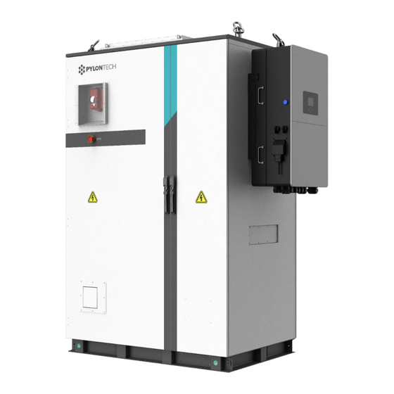
Pylontech M1C-UL9540 User Manual (122 pages)
Integrated Outdoor Lithium Iron Phosphate Battery Energy Storage System
Brand:
Pylontech
| Category:
Storage
| Size: 22.97 MB
Table of Contents
Table of Contents
2
1 Safety
5
Validity
5
Target Group
5
Safety Symbols Instructions
5
Safety of the Inverter
5
Safety Instructions
5
Safety of the System
7
Safety Symbols
7
Reference Standards
10
System Related Standards
10
Battery Related Standards
10
Inverter Related Standards
10
2 System Introduction
11
Parameters of the Outdoor Battery Cabinets
12
Parameters of 30Kw System
12
Parameters of 60Kw System
14
System Diagram
16
Diagram for 30Kw System
16
Diagram for 60Kw System
17
Introduction of the Inverter System
18
Products Descriptions
18
Inverter Components (30K-3P-208V/60K-3P-480V)
19
Packing List
20
Specifications
21
Parameters of the Inverter System
21
Dimensions of the Inverters
23
Torque Values Application Note
23
Wire Gauge Guide (Copper)
24
Wiring Diagrams
25
Introduction of the Battery System
25
Product Introduction
25
Accessories Package List of the Battery System
25
Accessories Package List for 10 Pcs of M1C Battery Modules
25
Inverter (30KW)]) (for One String)
25
Accessories Package List for 21 Pcs of M1C Battery Modules [Complied With1Pc of 60K-3P-480V Inverter (60KW)] (for One String Only)
28
Parameters of the Single Battery System
29
Battery Module (H32148-C)
30
Parameters of the Battery Module
30
Front Interface of the Battery Module
31
Control Module
32
Parameters of the Control Module
32
Control Module (SC1000-200J-C) Front Interface
33
System Diagram
36
Multiple Battery String in Parallel Connection by CAN Communication between MBMS and BMS Diagram (Battery String Qty. ≤6)
36
Safety Features Installed with the System
37
Fire Suppression System
38
3 System Installation and Operation
39
Outdoor Battery Cabinet Layout
39
External Dimensions
39
External Layout
40
Internal Layout
41
Installation Environment
42
Installation Clearance
42
Requirements of the Installation Foundation
44
Handling and Installation of the Cabinet
45
Cabinet Grounding
46
Installation and Operation of the Inverter
47
Deciding the Site's Backup Circuits
47
Grounding Cables Installation
47
Mounting the Inverter on the Outdoor Cabinet
47
Physical Installation (Small Commercial Backup)
48
Integrating Batteries (Inverter POWERED "OFF")
48
Sensors Integration and Accessory Placement
49
Powering-Up & Testing the Sol-Ark 30K-3P-208V
51
Remote Monitoring Setup
53
PV (Powerview)App of the Inverter
53
APP Connection and Setup
53
Start Monitoring the Data
56
IP Address Setup Instructions (PC or Smartphone)
56
GUI Screens
58
Programming Guide
60
Limiter Sensors (CT Sensors)
67
Installation Tips
69
Off-Grid Installation Tips
69
Grid-Tie / no Battery Install Tips
70
Batteries Charging Information
70
Installation and Operation of the Battery System
71
Preparing Tools and Safety Gear
71
System Working Environments Checking
72
Cables Connection
73
Battery System Power on
78
Battery System Power off
80
Operation of the Outdoor Battery Cabinet System
81
Outdoor Battery Cabinet System Power on
81
Black Start
81
Outdoor Battery Cabinet System Power off
81
Power off in Emergencies
81
4 System Debug and Maintenance
82
Personal Safety
82
Safety Precautions
82
Maintenance Intervals
82
Inverter System Troubleshooting
84
Inverter System Troubleshooting Guide
84
Troubleshooting Phasing Issues
86
Sol-Ark Inverter Error Codes
86
Battery System Debug and Maintenance
88
Battery System Debug
88
Trouble Shooting
89
Replacement of Main Component
92
Replacement of Battery Module
92
Replacement of Control Module (BMS)
93
Battery Maintenance
95
Emergency Disposal
96
EPO (Emergency Power off Switch)
96
Firefighting Equipment
96
5 Shipment and Storage
97
Shipment
97
Storage
97
Annex 1: Diagrams of 30K-3P-208V Inverter
98
Annex 2: Diagrams of 60K-3P-480V Inverter
107
Annex 3: Cable Connection Diagram (CAN ≤6 Set)
116
Annex 4: Cable Connection Diagram (Ethernet)
117
Annex 5: Installation and System Turn on Process List
118
Annex 6: System Turn off Process List
120
Advertisement
Advertisement
Related Products
Pylontech 48V148AH
Pylontech 48V222AH
Pylontech 48V296AH
Pylontech amber rock
Pylontech AR500
Pylontech Force-H1
Pylontech Force-H1-V2
Pylontech Force-H2-V2
Pylontech Force-H3
Pylontech Force-L2
Pylontech Categories
Camera Accessories
Storage
Battery Pack
Inverter
Switch
More Pylontech Manuals
Login
Sign In
OR
Sign in with Facebook
Sign in with Google
Upload manual
Upload from disk
Upload from URL