Table of Contents
Advertisement
Quick Links
Training Guide
Publication Number E2433-97034
First Edition, November 1997
For Safety information, Warranties, and Regulatory
information, see the pages behind the Index.
© Copyright Hewlett-Packard Company 1992–1997
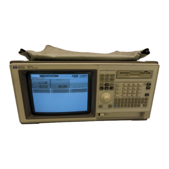
Training Kit for
HP 1660/70 Series Logic
Analyzers
Get other manuals https://www.bkmanuals.com
Advertisement
Table of Contents


Need help?
Do you have a question about the 1660 Series and is the answer not in the manual?
Questions and answers