
Subscribe to Our Youtube Channel
Related Manuals for Fisher & Paykel DCS RGS Series


Summary of Contents for Fisher & Paykel DCS RGS Series
- Page 1 RGS SERIES RANGE Service Manual MODELS: RGS-305 RGS-484GG RGS-366 RGS-486GL RGS-364GL RGS-486GD RGS-364GD RGS-485GD...
- Page 2 TO OUR VALUED SERVICE PARTNERS Fisher & Paykel is a leading manufacturer of premium quality (888) 281-5698. Remember, we are here to support you and cooking and specialty appliances under the Fisher & Paykel our customers. This service manual is designed to provide and DCS brands for both residential and professional use.
-
Page 3: Table Of Contents
TABLE OF CONTENTS Page GENERAL Safety Practices & Precautions ........................4-6 Model/Serial Number Location & Identifi cation ..................7 Model Identifi cation ............................8 TROUBLESHOOTING ............................9-10 WIRING AND SCHEMATIC DIAGRAMS ......................11-18 SERVICING THE COMPONENTS Component Locations ..........................19-22 Removing A Sealed Burner & Electrode ....................23-24 Removing A Main Jet Holder &... - Page 4 TABLE OF CONTENTS Page Backguard Installation ..........................69 Electrical And Gas Connections ......................70-71 Tests And Adjustments ...........................71-72 Installer Final Checklist ..........................73 USE AND CARE Before Using The Range .........................74-75 Cooktop Use ...............................76-78 Grill & Griddle Use ............................79-81 Oven Use ..............................82-86 Care And Maintenance ...........................87-91 Parts Identifi...
-
Page 5: General
GENERAL SAFETY PRACTICES & PRECAUTIONS When properly cared for, your new DCS Appliance is de- • Do not repair or replace any part of this appliance unless signed to be a safe, reliable cooking appliance. When using it is specifi cally recommended in this manual. All other this restaurant caliber appliance, use it with extreme care, servicing should be referred to a qualifi... - Page 6 GENERAL SAFETY PRACTICES & PRECAUTIONS • Be certain to use only dry pot holders: moist or damp pot • Never leave the cooktop unattended when using high holders on hot surfaces may cause burns from steam. Do fl ame settings. When cooking with high fl ame settings, not use a towel or other bulky or frayed cloth in place of a boil over may cause smoking and a greasy spill over pot holders.
- Page 7 GENERAL SAFETY PRACTICES & PRECAUTIONS • Do not use the grill for cooking excessively fatty meats or • Turn the ventilator OFF in case of fi re or when inten- products which promote fl are-ups. Do not use cooking tionally “fl aming” liquor or other spirits on the cooktop. utensils on the grill.
-
Page 8: Model/Serial Number Location & Identifi Cation
GENERAL MODEL / SERIAL NUMBER LOCATION & IDENTIFICATION Model Number / Serial Sticker Location MODEL NUMBER SERIAL NUMBER RGS-364GLSSN/L 04F02358B RGS 364 SS N/L 02358 A. Product Identifi er A. Year Of Manufacture RGS = Gas Range Series 04 = 2004 B. -
Page 9: Model Identification
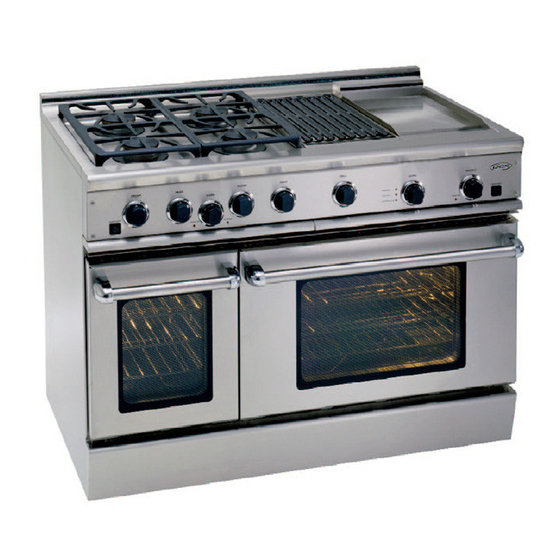
GENERAL MODEL IDENTIFICATION 48ʺ RGS RANGE MODELS RGS-484GG RGS-486GL RGS-486GD RGS-485GD 36ʺ RGS RANGE MODELS RGS-366 RGS-364GL RGS-364GD 30ʺ RGS RANGE MODELS OVEN ON HEATING HEATING DOOR LOCKED RGS-305... -
Page 10: Troubleshooting
TROUBLESHOOTING Problem Possible Cause Solution gas supply is not ON at wall valve gas supply is not ON behind kick panel will not work no gas or electric to unit tripped house breaker power cord is not plugged in at wall outlet disconnected main plug in control panel check for 120 vac to transformer no spark... - Page 11 TROUBLESHOOTING check convection blade for proper rotation convection fan working check for proper cooking utensils and placement of pan in oven check convection fan switch check for power to convection motor convection fan not working check for open winding on motor convection not working check that motor and blade turn free with no resistance or rubbing...
-
Page 12: Wiring And Schematic Diagrams
WIRING AND SCHEMATIC DIAGRAMS RGS-305 Model WIRING DIAGRAM Part #17574B... - Page 13 WIRING AND SCHEMATIC DIAGRAMS RGS-305 Model SCHEMATIC DIAGRAM Part #17574B...
- Page 14 WIRING AND SCHEMATIC DIAGRAMS RGS-36 Model WIRING DIAGRAM Part #17575B...
- Page 15 WIRING AND SCHEMATIC DIAGRAMS RGS-36 Models SCHEMATIC DIAGRAM Part #17575B...
- Page 16 WIRING AND SCHEMATIC DIAGRAMS RGS-48 Models WIRING DIAGRAM Part #17576B...
- Page 17 WIRING AND SCHEMATIC DIAGRAMS RGS-48 Models SCHEMATIC DIAGRAM Part #17576B...
- Page 18 WIRING AND SCHEMATIC DIAGRAMS RGS-485 Model WIRING DIAGRAM Part #17577B...
- Page 19 WIRING AND SCHEMATIC DIAGRAMS RGS-485 Model SCHEMATIC DIAGRAM Part #17577B...
-
Page 20: Servicing The Components
SERVICING THE COMPONENTS COMPONENT LOCATIONS This section instructs you on how to service each component inside the 30ʺ, 36ʺ, and 48ʺ Gas Ranges. The components and their locations for each of the three model sizes are shown on pages 43 through 46. 30ʺ... - Page 21 SERVICING THE COMPONENTS COMPONENT LOCATIONS 30ʺ & 36ʺ Model Oven & Kick Panel Components IR Burner & Ignitor Oven Light (1 of 2) Convection Motor Assembly (Behind Cover) Bake Burner (Below Bottom Liner) Regulator Ignitor (Behind Kick Panel) Shutoff 30ʺ & 36ʺ Model Rear Components Dual (IR &...
- Page 22 SERVICING THE COMPONENTS COMPONENT LOCATIONS 48ʺ Model Cooktop Components Sealed Burners Grill With Jet Holders & Simmer Jet Holders Griddle Griddle Transformer Main Oven 12ʺ Oven Reignition Conv. Fan Pilot Light Thermal Light Switch Light Switch Module Switch Valve 12ʺ Oven Griddle Grill Dual Flow Valve...
- Page 23 SERVICING THE COMPONENTS COMPONENT LOCATIONS 48ʺ Model Rear Components Dual (IR & Bake Burners) Thermal Valve...
-
Page 24: Removing A Sealed Burner & Electrode
SERVICING THE COMPONENTS REMOVING A SEALED BURNER & ELECTRODE Remove the 1-1/16ʺ venturi nut from the simmer ring WARNING and lift the ring off the burner base. Venturi Nut Electrical Shock Hazard Disconnect power before servicing. Replace all parts and panels before operating. Failure to do so can result in death or electrical shock. - Page 25 SERVICING THE COMPONENTS REMOVING A SEALED BURNER & ELECTRODE To remove the electrode from the burner base, turn the Electrode C-Ring & Spring base over, unclip the c-ring, and remove the spring and the electrode.
-
Page 26: Removing A Main Jet Holder & A Simmer Jet Holder
SERVICING THE COMPONENTS REMOVING A MAIN JET HOLDER & A SIMMER JET HOLDER To remove a main jet holder: WARNING a) Remove the 9/16” gas line nut. b) Remove the 1-1/8” nut and remove the main jet holder from the bracket. Main Jet Holder Nut Gas Line Nut Electrical Shock Hazard... -
Page 27: Removing The Cooktop-30ʺ & 36ʺ Models
SERVICING THE COMPONENTS REMOVING THE COOKTOP – 30” & 36” MODELS Pull the burner and thermostat knobs off the control WARNING shafts. Electrical Shock Hazard Disconnect power before servicing. Control Knob Replace all parts and panels before operating. Failure to do so can result in death or electrical shock. - Page 28 SERVICING THE COMPONENTS REMOVING THE COOKTOP – 30” & 36” MODELS Remove the four torx screws from the left and right 12. Lift the front of the cooktop, and remove it from the sides (two on each side) of the valve panel. range.
-
Page 29: Removing The Grill Burner & Ignitor
SERVICING THE COMPONENTS REMOVING THE GRILL BURNER & IGNITOR Lift the front of the radiant tray and remove it from over WARNING the grill. Radiant Tray Electrical Shock Hazard Disconnect power before servicing. Replace all parts and panels before operating. Failure to do so can result in death or electrical shock. - Page 30 SERVICING THE COMPONENTS REMOVING THE GRILL BURNER & IGNITOR To remove the grill burner ignitor: d) Remove the two front grill screws. a) Remove the burner (see step 4). 2 Front Grill Screws b) Remove the two screws and nuts from the ig- nitor bracket and remove the ignitor.
-
Page 31: Removing The Griddle Burner & Ignitor
SERVICING THE COMPONENTS REMOVING THE GRIDDLE BURNER & IGNITOR If not already done, remove the shipping screw and fl at WARNING washer from the rear of the griddle. Remove the two screws from the front of the griddle. Front Screws Shipping Screw &... - Page 32 SERVICING THE COMPONENTS REMOVING THE GRIDDLE BURNER & IGNITOR b) Slide the griddle burner back so that the air shut- To remove the griddle burner ignitor: ter is off the orifi ce of the single thermal valve, a) Remove the griddle burner (see step 8). and remove the burner.
-
Page 33: Removing A Fan Or Light Switch & A Pilot Light
SERVICING THE COMPONENTS REMOVING A FAN OR LIGHT SWITCH & A PILOT LIGHT GL & GD Models Only: Pull the drip pan out and place WARNING a soft cloth on the drip pan to protect the valve panel surface. Rotate the valve panel onto the drip pan (if present), or on the oven door handle so you can access the com- ponents. - Page 34 SERVICING THE COMPONENTS REMOVING A FAN OR LIGHT SWITCH & A PILOT LIGHT To remove a fan or light switch: Light/Fan Switch Connectors a) Disconnect the wire from the switch terminals. b) Press in on the two side tabs and push the switch out of the panel opening.
-
Page 35: Removing A Burner Switch & Dual Flow Valve
SERVICING THE COMPONENTS REMOVING A BURNER SWITCH & DUAL FLOW VALVE WARNING Electrical Shock Hazard Disconnect power before servicing. Replace all parts and panels before operating. Failure to do so can result in death or electrical shock. C-Clip Wire Connectors Turn off... - Page 36 SERVICING THE COMPONENTS REMOVING A BURNER SWITCH & DUAL FLOW VALVE REASSEMBLY NOTES: Dual Flow Valve Clamp Screws When replacing the dual fl ow valve on the manifold: • Make sure that you tighten the clamp screws evenly. • Make sure that the rubber seal is on the valve before mounting the valve to the manifold.
-
Page 37: Removing The Transformer & Reignition Module
SERVICING THE COMPONENTS REMOVING THE TRANSFORMER & REIGNITION MODULE To remove the transformer: WARNING a) Remove the two nuts from the screws and re- move the two screws from the transformer. b) Remove the ceramic nuts from the wires, sepa- rate the wires, and remove the transformer pri- mary and secondary wires. - Page 38 SERVICING THE COMPONENTS REMOVING THE TRANSFORMER & REIGNITION MODULE To remove the reignition module: Reignition Module Burner Wires Screw a) Pull the primary wiring connector off the reigni- tion module. b) Remove the two screws from the reignition mod- ule and pull the module out as far as possible. c) Note the wire locations, and then disconnect the burner wires from the reignition module and remove the module.
-
Page 39: Removing A Grill Or Griddle Single Thermal Valve
SERVICING THE COMPONENTS REMOVING A GRILL OR GRIDDLE SINGLE THERMAL VALVE Remove the two 9/16ʺ gas line nuts from the gas line WARNING between the thermal valve and the manual valve, and remove the gas line. Remove the two screws from the thermal valve brack- Thermal Valve Bracket Screws Electrical Shock Hazard Disconnect power before servicing. - Page 40 SERVICING THE COMPONENTS REMOVING A GRILL OR GRIDDLE SINGLE THERMAL VALVE Pull the single thermal valve forward, disconnect the two wires from the terminals, and remove the thermal valve. Thermal Valve Wire Connectors...
-
Page 41: Removing A Thermostat
SERVICING THE COMPONENTS REMOVING A THERMOSTAT b) Disconnect the wires from the thermostat ter- WARNING minals. Electrical Shock Hazard Disconnect power before servicing. Replace all parts and panels before operating. Failure to do so can result in death or electrical shock. - Page 42 SERVICING THE COMPONENTS REMOVING A THERMOSTAT b) Disconnect the wires from the main oven ther- To remove the 12ʺ oven thermostat: mostat terminals. a) Remove the capillary bulb from the liner clips by squeezing the clips together, and removing Main Oven Thermostat them from the liner holes.
-
Page 43: Removing The Dual Thermal Valve (Main Oven)
SERVICING THE COMPONENTS REMOVING THE DUAL THERMAL VALVE (MAIN OVEN) Remove the inlet and two outlet gas lines from the dual WARNING thermal valve. Disconnect the four wire connectors from the dual thermal valve terminals. Dual Thermal Valve Gas Inlet Line Electrical Shock Hazard Disconnect power before servicing. - Page 44 SERVICING THE COMPONENTS REMOVING THE DUAL THERMAL VALVE (MAIN OVEN) Remove the cooktop, grill, or griddle from the range Dual Valve Screws Griddle Well (see pages 50, 52, or 54 for the procedure). While holding the dual valve in place, remove the two mounting screws from the chassis, and remove the valve.
-
Page 45: Removing The Infrared (Ir) Burner & Ignitor
SERVICING THE COMPONENTS REMOVING THE INFRARED (IR) BURNER & IGNITOR WARNING 6 Island Back Trim Screws Electrical Shock Hazard Disconnect power before servicing. Disconnect the 9/16ʺ nut from the gas line at the IR Replace all parts and panels before operating. burner. - Page 46 SERVICING THE COMPONENTS REMOVING THE INFRARED (IR) BURNER & IGNITOR 10. To remove the IR Ignitor, remove the two screws for the 11. To remove the IR burner, remove the 10 screws around ignitor plate at the rear of the oven cavity, and remove the outside of the IR burner, (support the burner with the ignitor.
-
Page 47: Removing An Oven Lamp Assembly
SERVICING THE COMPONENTS REMOVING AN OVEN LAMP ASSEMBLY Slide the fl at spring out of the lampholder. WARNING Electrical Shock Hazard Disconnect power before servicing. Replace all parts and panels before operating. Failure to do so can result in death or electrical shock. - Page 48 SERVICING THE COMPONENTS REMOVING AN OVEN LAMP ASSEMBLY Use a fl at screwdriver and pry the four locking tabs up on the lampholder at about 45°. Pull the lampholder into the oven and disconnect the three wires from the holder terminals. NOTE: The wire connectors are sized for proper polarity.
-
Page 49: Removing The Convection Motor
SERVICING THE COMPONENTS REMOVING THE CONVECTION MOTOR Remove the four machine screws from the convection WARNING motor assembly plate and lay the assembly in the bot- tom of the oven cavity. Electrical Shock Hazard Disconnect power before servicing. Replace all parts and panels before operating. Failure to do so can result in death or electrical shock. - Page 50 SERVICING THE COMPONENTS REMOVING THE CONVECTION MOTOR Loosen the two Allen setscrews on the convection blade 10. Cut the wire tie from around the motor wires. and remove the blade. NOTE: When reassembling, use a new wire tie. 11. Remove the four locknuts and remove the motor from the bracket.
-
Page 51: Removing The Main Oven Bake Burner & Ignitor
SERVICING THE COMPONENTS REMOVING THE MAIN OVEN BAKE BURNER & IGNITOR Lift the front of the oven fl oor and slide it out of the WARNING oven. To remove the main oven bake burner: a) Remove the screw from the rear of the burner. Electrical Shock Hazard Disconnect power before servicing. - Page 52 SERVICING THE COMPONENTS REMOVING THE MAIN OVEN BAKE BURNER & IGNITOR To remove the main oven bake burner ignitor: c) Remove the two screws and nuts from the bake burner ignitor and remove the ignitor. a) Remove the two screws from the kick panel, then pull the top of the panel forward, slide the two nylon tabs from their catches, and remove the panel.
-
Page 53: Removing The 12ʺ Oven Bake Burner, Burner Ignitor, & Thermal Valve
SERVICING THE COMPONENTS REMOVING 12ʺ OVEN BAKE BURNER, BURNER IGNITOR, & THERMAL VALVE WARNING Electrical Shock Hazard Disconnect power before servicing. Replace all parts and panels before operating. Failure to do so can result in death or electrical shock. Oven Floor Turn off... - Page 54 SERVICING THE COMPONENTS REMOVING 12ʺ OVEN BAKE BURNER, BURNER IGNITOR, & THERMAL VALVE To remove the 12ʺ oven bake burner ignitor and ther- e) Disconnect the two wire connectors from the mal valve: thermal valve terminals, and remove the thermal valve and ignitor.
-
Page 55: Removing An Oven Door
SERVICING THE COMPONENTS REMOVING AN OVEN DOOR Fully open the oven door. Close the door until you feel resistance, then continue to lift the door until the hinges begin to slide out of the Rotate the hinge hanger clips to the locked position. chassis slots, and remove the hinges and door from the range. -
Page 56: Removing A Hinge Receptacle
SERVICING THE COMPONENTS REMOVING A HINGE RECEPTACLE Remove the oven door (see page 78 for the door re- Rotate the hinge receptacle so that the bottom is out of moval procedure). the slot, grasp the bottom with your hand, and remove the receptacle. -
Page 57: Removing The Oven Door Handle, Hinge, And Window Pack
SERVICING THE COMPONENTS REMOVING THE OVEN DOOR HANDLE, HINGE, AND WINDOW PACK Remove the fi ve top and fi ve bottom screws from the Remove the oven door (see page 78 for the door re- door. moval procedure), and position it on a padded surface with the hinges pointing up. - Page 58 SERVICING THE COMPONENTS REMOVING THE OVEN DOOR HANDLE, HINGE, AND WINDOW PACK To remove the door hinge: c) Remove the large insulation from the door a) Loosen the indicated side hinge bracket screw and fl at washer. b) Remove the two bottom hinge screws and lift the hinge out of the door liner.
-
Page 59: Testing The Components
TESTING THE COMPONENTS WARNING Electrical Shock Hazard Disconnect power before servicing. Replace all parts and panels before operating. Failure to do so can result in death or electrical shock. Before testing any of the components, perform the follow- • Check all connections before replacing components, ing checks: looking for broken or loose wires, failed terminals, or connectors not pressed onto terminals far enough. -
Page 60: Ignitor
TESTING THE COMPONENTS WARNING Electrical Shock Hazard Disconnect power before servicing. Replace all parts and panels before operating. Failure to do so can result in death or electrical shock. IGNITOR CONVECTION MOTOR Refer to pages 52 (grill), 54 (griddle), 68 (IR), 74 (main Refer to page 72 for the procedure for servicing the convec- oven), and 76 (12ʺ... -
Page 61: Single Thermal Valves
TESTING THE COMPONENTS WARNING Electrical Shock Hazard Disconnect power before servicing. Replace all parts and panels before operating. Failure to do so can result in death or electrical shock. SINGLE THERMAL VALVES (N.C.) DUAL THERMAL VALVE (N.C.) (GRIDDLE & GRILL) (MAIN OVEN BAKE &... -
Page 62: Installation Instructions
INSTALLATION INSTRUCTIONS INTRODUCTION IMPORTANT INSTALLATION INFORMATION Installation, electrical connections, and grounding must The RGS series ranges are tested in accordance with ANSI comply with all applicable codes. In the absence of local Z21.1 Standard for Household Cooking Gas Appliances. codes, the range should be installed in accordance with These ranges must be installed in conjunction with a suit- the National Fuel Gas Code ANSI Z223.1, latest edition, and able overhead vent hood (see “Ventilation Requirements”... -
Page 63: Planning The Installation
INSTALLATION INSTRUCTIONS PLANNING THE INSTALLATION IMPORTANT INSTALLATION INFORMATION RECOMMENDED INSTALLATION INSTRUCTION The RGS is tested in accordance with ANSI Z21.1 Standard Install components in the following order: for Household Cooking Gas Appliances. A) Vent Hood The range must be installed in conjunction with a suitable B) Backguard System overhead vent hood. -
Page 64: Unpacking And Handling
INSTALLATION INSTRUCTIONS UNPACKING AND HANDLING MOVING AND PLACING THE RANGE Remove the kick panel by removing two screws at the top and pulling forward. The range is held to the skid by two The ranges have shipping weights varying from 380 to 600 bolts in the front behind the kick panel, and two L-brack- pounds. - Page 65 INSTALLATION INSTRUCTIONS UNPACKING AND HANDLING GRIDDLE LEVEL ADJUSTMENTS The grill and griddle sections (if equipped) are fastened DOOR HINGE ROLLER in place at the front with screws. They are designed to be stationary and not meant to be removed for cleaning. The griddle has two leveling screws beneath the rear fl...
-
Page 66: Ventilation Requirements
INSTALLATION INSTRUCTIONS VENTILATION REQUIREMENTS A suitable exhaust hood must be installed above the range. The following chart indicates the minimum blower capacity recommended for hood ventilation. VENTILATION STANDARD COUNTER ISLAND UNIT INSTALLATION INSTALLATION RECOMMENDATIONS RECOMMENDATIONS HOOD (24” Deep x Unit Width) (30”... -
Page 67: Installing The Anti-Tip Device
INSTALLATION INSTRUCTIONS INSTALLING THE ANTI-TIP DEVICE All ranges must have an Anti-tip device correctly installed (2) Wood screws as per the following instructions. If you pull the range out (2) Small holes into back wall (all from the wall for any reason, make sure that the device is for wood installations) properly engaged when you push the range back against... -
Page 68: Cabinet Preparation
INSTALLATION INSTRUCTIONS CABINET PREPARATION The range is a free standing unit. If the unit is to be When there is less than a 12” clearance between placed adjacent to cabinets, the clearances shown be- combustible material and the back edge of the range, low for Models RGS-48 &... - Page 69 INSTALLATION INSTRUCTIONS CABINET PREPARATION 12″ Min. to Combustibles Δ without backguard 36″ Min. to Combustibles Δ 0″ Clearance 0” Clearance Δ As defined in the “National Fuel Gas Code” (ANSI Z223.1, lastest edition). The horizontal surfaces of the range top (cooktop) trim must not be below countertop level.
-
Page 70: Backguard Installation
INSTALLATION INSTRUCTIONS BACKGUARD INSTALLATION BACKGUARD KITS Wall Mount The backguard is located as shown in the illustration. Secure Full Backguard the backguard to the wall behind the range. Specifi c instruc- (Model #’s BGS-3030, BGS-3036, BGS-3048) tions for installation of the full backguard or low backguard can be found packaged with the backguard. -
Page 71: Electrical And Gas Connections
INSTALLATION INSTRUCTIONS ELECTRICAL AND GAS CONNECTIONS ELECTRICAL CONNECTIONS GAS REQUIREMENTS Power Requirements Range: Verify the type of gas supplied to the location. The range is shipped from the factory set up and adjusted for natural • 120 VAC, 60 Hz., single phase gas or L.P. -
Page 72: Tests And Adjustments
INSTALLATION INSTRUCTIONS ELECTRICAL AND GAS CONNECTIONS The appliance and its individual shut-off CAUTION: valve must be disconnected from the gas The appliance must be isolated from the supply piping system during any pressure building’s gas supply piping system by testing of the system at the test pressures in closing its individual manual shut-off... - Page 73 INSTALLATION INSTRUCTIONS TESTS AND ADJUSTMENTS ADJUSTING THE GRIDDLE AND GRILL BURNERS COOKTOP BURNERS Check for the proper burner fl ame characteristics and adjust The surface burners are not adjustable. Proper operation air shutters if necessary. is achieved when the correct orifi ces for gas supply are installed at the factory, based on model ordered.
-
Page 74: Installer Final Checklist
INSTALLATION INSTRUCTIONS INSTALLER FINAL CHECKLIST GENERAL OPERATION Placement of unit. All internal packing materials are removed. Check below grates, pans, and drip drawers. Specifi ed clearance maintained to cabinet surfaces. Grill (if equipped) compartment sealed and does not Unit Level- front to back, side to side. rock. -
Page 75: Use And Care
USE AND CARE BEFORE USING THE RANGE Remove all packaging material instructions (for insulation) 12ʺ OVEN from your appliance. If the installer has not set up your ap- • Two oven racks pliance, do it now. • Two removable side rails Check to make sure that you have the following items: Do not use aluminum foil to cover the oven racks or to line the oven. - Page 76 USE AND CARE BEFORE USING THE RANGE INSTALLING THE OVEN RACKS TO REMOVE OR REPOSITION THE OVEN RACKS Hold the rack with the back safety rail in the up position Pull the rack forward as far as the stop. and towards the rear of the oven. Slip it into the oven Lift the front of the rack up so the safety stops clear the so the rack slides are between the rack and the rack rack slides.
-
Page 77: Cooktop Use
USE AND CARE COOKTOP USE BURNERS SIMMERING Your new professional gas range is equipped with burn- Your new professional cooktop has exceptionally low sim- ers typical of those used in restaurants. These burners mering capabilities. The large cap serves as a heat diff user are designed for easy cleaning and control. - Page 78 USE AND CARE COOKTOP USE SEALED TOP BURNERS BURNER EFFICIENCY AND FLAME The sealed top burners must be kept clean. Cleaning of the CHARACTERISTICS sealed top burners should include the igniter. The cooktop It is necessary to keep the burner ports and the igniters clean burners have an infi...
- Page 79 USE AND CARE COOKTOP USE COOKWARE WOK RING For best results we recommend using professional cook- A wok ring accessory is available for your new DCS appli- ware. This type of utensil can be found at your fi ner depart- ance.
-
Page 80: Grill & Griddle Use
USE AND CARE GRILL & GRIDDLE USE GRILL aff ect the cooking. Do not replace the radiant tray/ceramic rods with alternates. Contact DCS for genuine factory-direct The grill grates are reversible. Place the side with the two replacement parts. grooved tabs towards the rear of the cooktop. The grill grates are made of durable porcelain enameled cast iron. - Page 81 USE AND CARE GRILL & GRIDDLE USE EXCESSIVE FLARE UPS AND FLAMING GRIDDLE Occasionally grease drippings ignite. These drippings will The built-in griddle on your cooktop is made from Type create minor puff s of fl ame for a second or two. This is nor- 304 stainless steel, highly polished to provide a smooth mal when cooking on a grill.
- Page 82 USE AND CARE GRILL & GRIDDLE USE USE OF THE GRIDDLE BEFORE USING THE GRIDDLE FOR THE FIRST Before starting to cook on the griddle, be sure the drip tray TIME OR TO RE-SEASON and liners are in place. Preheat griddle for 15 minutes with Clean the griddle thoroughly with hot, soapy water to the control knob set to the temperature suggested on the remove any protective coating.
-
Page 83: Oven Use
USE AND CARE OVEN USE OVEN BURNERS PREHEATING Your new professional RGS range is equipped with bake and Preheating takes about 10 to 15 minutes depending on the broil oven burners. The oven broiler burner is 19,000 Btu/hr. temperature set. Preheating is usually necessary for foods on RGS models. - Page 84 USE AND CARE OVEN USE REGULAR BAKING CONVECTION BAKING Bake is baking with hot air; there is no fan. The air movement Convection Baking is baking with the fan at the back of the comes from natural convection. As the air heats, it moves oven circulating the hot air in a continuous pattern around to the top of the oven.
- Page 85 USE AND CARE OVEN USE When reducing the temperature always check the food for To Get The Best Results doneness, a minute to two before the minimum time stated • Metal utensils give better results, in convection, than do in the recipe, as time can always be added. Some recipes glass baking utensils.
- Page 86 USE AND CARE OVEN USE Foods Suitable For Broil • When top browning, use metal or glass-ceramic bake- ware. DO NOT use heatproof glass or pottery as this type • Top Browning: Casseroles & Breads of glassware cannot withstand the intense heat of the •...
- Page 87 USE AND CARE OVEN USE A large two-piece broil pan comes with your new range. • To thaw uncooked frozen food, set the oven control knob When you are broiling, always use both pieces. Do not to “warm. ” Be sure the food is tightly wrapped in foil. Thaw cover the grid with aluminum foil.
-
Page 88: Care And Maintenance
USE AND CARE CARE AND MAINTENANCE WHEN CLEANING THE RANGE The occasional use of mild abrasive cleansers or a soap-fi lled steel wool pad is permissible. However, abrasive cleansers Be careful cleaning any part of this appliance while hot. used vigorously, or too often, can eventually harm the All parts of the appliance can be cleaned with hot soapy enamel. - Page 89 USE AND CARE CARE AND MAINTENANCE BURNERS Reassemble the burner parts, and secure them with the hex nut. After cleaning, it is important to make sure the locat- For proper lighting and performance, keep the burners ing pin on the bottom side of the simmer ring is properly clean.
- Page 90 USE AND CARE CARE AND MAINTENANCE GRIDDLE GRILL While still hot, thoroughly clean all grease and food particles Clean the grill immediately after cooking. Turn off the from the griddle , using a square-edged spatula. When the burner. To protect your hand from steam and heat, wear griddle is warm, rub the surface lightly with vegetable oil.
- Page 91 USE AND CARE CARE AND MAINTENANCE OVEN AND DOOR INTERIOR BACKGUARD Be sure the oven and door are cool before you start to The backguard is made of stainless steel. Use the mildest clean them. They are porcelain enamel. It is acid resistant, cleaning procedure fi...
- Page 92 USE AND CARE CARE AND MAINTENANCE FRAME, SIDES, DOOR EXTERIOR, HEAT CAUTION: Be sure the oven light switch is in the OFF po- DEFLECTOR sition and the cover is cool. If the bulb comes These parts are made of stainless steel. Follow the direc- loose from the base, turn off...
-
Page 93: Parts Identification
USE AND CARE PARTS IDENTIFICATION ITEM DESCRIPTION ITEM DESCRIPTION Grill Large Oven Racks Burner Grates Broil Pan Locator Rack Griddle Oven Door Grill Grates 12” Oven Door Large Oven Control Knob Oven Racks (2) Small Oven Griddle Control Knob Cooktop Control Knob Oven Light Switch Small Oven Control Knob Grill Control Knob... -
Page 94: Warranty
WARRANTY LIMITED WARRANTY When you purchase a new DCS Range you automatically receive a One Year Limited Warranty covering parts and labor for the entire product, a Five Year Limited Warranty on surface burners, griddle burners, grill burner and oven burners (parts only), and a Two Year Limited Warranty on the porcelain oven liner and porcelain inner door panel (parts only) for servicing within the 48 mainland United States, Hawaii, Washington D.C. - Page 95 WARRANTY Defects caused by factors other than: 1. Normal domestic use or 2. Use in accordance with the Product’s Use and Care Guide. C. Defects to the Product caused by accident, neglect, misuse, fi re, fl ood or Act of God. D.
- Page 96 Fisher & Paykel Appliances, Inc. 5900 Skylab Road, Huntington Beach, CA 92647 Customer Care: 888.281.5698 Fax: 714.372.7003 www.dcsappliances.com As product improvement is an ongoing process at DCS, we reserve the right to change specifi cations or design without notice. P/N 17730 Rev. B Litho in USA 10/2005...
Need help?
Do you have a question about the DCS RGS Series and is the answer not in the manual?
Questions and answers
Hi, I need buy the ignitor for 12" Oven. I’d like to know the code of this part. Would you be able to provide it?
I am looking for the service manual for model number CPU – 366 – L DCS US CA Could you please send it to me thank you