
Subscribe to Our Youtube Channel
Related Manuals for Fisher & Paykel DCS RGS Series


Summary of Contents for Fisher & Paykel DCS RGS Series
- Page 1 RGS SERIES RANGE Installation Guide MODELS: RGS-305 RGS-484GG RGS-366 RGS-486GL RGS-486GD RGS-364GL RGS-364GD RGS-485GD...
- Page 2 A MESSAGE TO OUR CUSTOMERS Thank you for selecting this DCS RGS Gas Range. Because of this appliance’s unique features we have developed this Installation Guide. It contains valuable information on how to properly operate and maintain your new appliance for years of safe and enjoyable cooking. For your convenience, product questions can be answered by a DCS Customer Care Representative by phone: 1-888-281-5698, email: support@dcsappliances.com, or by mail: Fisher &...
-
Page 3: Table Of Contents
TABLE OF CONTENTS INTRODUCTION ..................................3 MODELS ....................................4 PLANNING THE INSTALLATION ..........................5-6 UNPACKING AND HANDLING ..........................6-8 VENTILATION REQUIREMENTS ..........................9 INSTALLING ANTI-TIP DEVICE ..........................10 CABINET PREPARATION ............................11-13 BACKGUARD INSTALLATION ..........................13 ELECTRICAL / GAS CONNECTIONS ......................14-15 TEST AND ADJUSTMENTS ..........................15-16 INSTALLER FINAL CHECKLIST ..........................17 HOW TO OBTAIN SERVICE ............................18... -
Page 4: Introduction
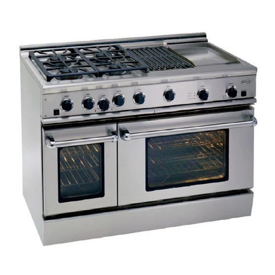
INTRODUCTION The DCS RGS series ranges are designed with a large number of features available in a multitude of different combinations. Patented Dual Flow Burners allow for consistently lower simmer temper- atures and have a high output of 17,500 Btu/hr. Also available on the ranges are an 18,000 Btu/hr griddle and/or grill. - Page 5 SAFETY PRACTICES & PRECAUTIONS When properly cared for, your new DCS Appliance is designed to be a safe, reliable cooking appliance. When using this restaurant caliber appliance, use it with extreme care, as this type of appliance provides intense heat and can increase the accident potential. Basic safety precautions must be followed when using kitchen appliances, including the following: Read this Use and Care Manual thoroughly before using your new appliance.
- Page 6 SAFETY PRACTICES & PRECAUTIONS For personal safety, wear proper apparel. Loose fitting garments or hanging sleeves should never be worn while using this appliance. Some synthetic fabrics are highly flammable and should not be worn while cooking. Do not use aluminum foil to line any part of the oven or cooktop. Using a foil liner could result in a fire hazard, or the obstruction of the flow of combustion and ventilation air.
- Page 7 SAFETY PRACTICES & PRECAUTIONS Be sure all the range and/or cooktop controls are turned off and the appliance is cool before using any type of aerosol cleaner on or around the appliance. The chemical that produces the spraying action could, in the presence of heat, ignite or cause metal parts to corrode. Place oven racks in desired position while the oven is cool.
-
Page 8: Models
MODELS 48” RGS RANGE MODELS RGS-484GG RGS-486GL RGS-486GD RGS-485GD 36” RGS RANGE MODELS RGS-366 RGS-364GL RGS-364GD 30” RGS RANGE MODELS OVEN ON HEATING HEATING DOOR LOCKED RGS-305... -
Page 9: Planning The Installation
PLANNING THE INSTALLATION IMPORTANT INSTALLATION INFORMATION The RGS is tested in accordance with ANSI Z21.1 Standard for Household Cooking Gas Appliances. The range must be installed in conjunction with a suitable overhead vent hood. (See ventilation requirements, page 9). Due to the professional high heat capacity of this unit, particular attention should be paid to the hood and duct work installation to ensure it meets local building codes. -
Page 10: Unpacking And Handling
PLANNING THE INSTALLATION RECOMMENDED INSTALLATION INSTRUCTION Install components in the following order: A) Vent Hood B) Backguard System C) Range 1) Locate and level range according to range installation instructions. 2) Measure distance from floor to top of island trim on range adding 1/8” for backguard clearance. 3) Transfer this measurement to the wall. - Page 11 UNPACKING AND HANDLING CAUTION Proper equipment and adequate manpower must be used in moving the range to avoid damage to the unit or the floor. The unit is heavy and rests on adjustable steel legs. WARNING: DO NOT lift range by the oven door handles or drip pan handle!! WARNING DO NOT remove the grill or griddle assemblies!! It may be necessary to remove the oven doors and...
- Page 12 UNPACKING AND HANDLING After checking the countertops for level and DOOR HINGE ROLLER- before sliding the range into place, measure RIGHT the distance from the floor to the top of the DOOR HINGE ROLLER counter work surface in the rear left and right corners.
-
Page 13: Ventilation Requirements
VENTILATION REQUIREMENTS A suitable exhaust hood must be installed above the range. The following chart indicates the minimum blower capacity recommended for hood ventilation. VENTILATION STANDARD COUNTER ISLAND UNIT INSTALLATION INSTALLATION RECOMMENDATIONS RECOMMENDATIONS HOOD (24" Deep x Unit Width) (30" Deep x 36" at Bottom) BLOWER *48"... -
Page 14: Installing Anti-Tip Device
INSTALLING ANTI-TIP DEVICE All ranges must have an anti-tip device (2) Wood Screws into correctly installed as per the following Back Wall (ALL Installations) instructions. If you pull the range out (2)Small Holes for from the wall for any reason, make sure Wood Installations that the device is properly engaged when you push the range back against... -
Page 15: Cabinet Preparation
CABINET PREPARATION 1) The range is a free standing unit. If the unit is to be placed adjacent to cabinets, the clearances shown in fig. 10 (RGS-48 & 36) & fig. 12 (RGS-305) are required. The same clearances apply to island installations. - Page 16 CABINET PREPARATION 12" Min. to Combustibles without backguard 36" Min. to Combustibles 0” Clearance 0” Clearance ∆ As defined in the “National Fuel Gas Code” (ANSI Z223.1, lastest edition). The horizontal surfaces of the range top (cooktop) trim must not be below countertop level. Fig.
-
Page 17: Backguard Installation
CABINET PREPARATION min. 30" wide hood 13" CAUTION: 12" min. to combustible 36" min. to material , each side combustible 18" Min. material , from cooking 4" 12" 4" 1 2 " surface cooking surface 3-1/4 " 3-1/2 " gas supply electrical supply 35-3/8"... -
Page 18: Electrical / Gas Connections
ELECTRICAL / GAS CONNECTIONS ELECTRICAL CONNECTIONS Receptacle Box Receptacle Box Cover Plate Power Requirements Range: Cover Plate 120 VAC, 60 Hz., single phase Three Prong Three Prong RGS-305: 4 Amp. Max. Plug Plug RGS-36: 7 Amp. Max. (use 15 Amp. circuit) RGS-48: 13 Amp. -
Page 19: Test And Adjustments
ELECTRICAL / GAS CONNECTIONS CAUTION: The appliance must be isolated from the building’s gas supply piping system by closing its individual manual shut-off valve during any pressure testing of the gas supply piping system at test pressures equal to or less than 1/2 psig (3.5kPa.). - Page 20 TEST AND ADJUSTMENTS THIS ADJUSTMENT SECTION APPLIES TO THE GRIDDLE AND GRILL BURNERS Check for the proper burner flame characteristics and adjust air shutters if necessary (fig. 16). Each air shutter is air shutter individually tested and adjusted prior to shipment. Normally adjustment is not required, however, vibration during transit, gas conversion or variations in the local gas supply may make minor adjustments necessary.
-
Page 21: Installer Final Checklist
INSTALLER FINAL CHECKLIST GENERAL Placement of unit. Specified clearance maintained to cabinet surfaces. Unit Level - front to back, side to side. All packaging material and tie straps removed, drip pans clean and empty. Backguard attached if there is less than 12" clearance above the cooking surface to combustibles behind unit. -
Page 22: How To Obtain Service
HOW TO OBTAIN SERVICE For warranty service, please contact DCS Customer Service Represenatative at (888) 281-5698. Before you call, please have the following information ready: Model Number (located on the rating plate above the kick panel on the right) Serial Number (located on the rating plate above the kick panel on the right) Date of installation A brief description of the problem Your satisfaction is of the utmost importance to us. -
Page 23: Warranty
WARRANTY Length of Warranty: One (1) Year Full – Covers the entire product (parts and labor). Five (5) Year Limited – Surface burners, oven burner (parts only). Ten (10) Year Limited – Porcelain oven, porcelain inner door panel (parts only). Any cosmetic defects must be reported within 30 days from date of installation. - Page 24 NOTES...
- Page 25 NOTES...
- Page 26 CUISINIÈRE DE SÉRIE RGS Guide d'installation MODÈLES : RGS-305 RGS-484GG RGS-366 RGS-486GL RGS-486GD RGS-364GL RGS-364GD RGS-485GD...
- Page 27 À L'INTENTION DE NOS CLIENTS Nous vous remercions d'avoir choisi cette cuisinière à gaz RGS DCS. Nous avons conçu ce Manuel d'instal- lation pour expliquer ses fonctions uniques. Il contient des informations extrêmement utiles sur la façon de faire fonctionner et d'entretenir correctement votre nouvel appareil. Vous pourrez ainsi en profiter pendant des années en toute sécurité.
- Page 28 TABLE DES MATIÈRES INTRODUCTION ..................................3 MESURES DE SÉCURITÉ ............................4-7 MODÈLES ....................................8 PLANIFICATION DE L'INSTALLATION ......................9-10 DÉBALLAGE ET MANIPULATION ........................11-12 EXIGENCES EN MATIÈRE DE VENTILATION ....................13 INSTALLATION DU DISPOSITIF ANTIBASCULEMENT .................14 PRÉPARATION DES ARMOIRES ........................15-17 INSTALLATION DU DOSSERET ..........................17 CONNEXIONS ÉLECTRIQUES OU À GAZ ....................18-19 ESSAI ET RÉGLAGES ...............................19-20...
-
Page 29: Introduction
INTRODUCTION Les cuisinières de série RGS DCS sont dotées de nombreuses fonctions offertes dans une multitude de combinaisons variées. Les brûleurs à double débit brevetés permettent des températures de mijotage constamment plus basses et dégagent une puissance de 17 500 BTUH. Également disponibles sur les cuisinières : plaque chauffante et/ou gril de 18 000 BTUH avec contrôle de température. -
Page 30: Mesures De Sécurité
MESURES DE SÉCURITÉ ET DE PRÉCAUTION Votre nouvel appareil DCS fonctionnera de manière sûre et fiable pendant des années si vous en prenez bien soin. Faites extrêmement attention quand vous utilisez cet appareil de niveau profes- sionnel, car il dégage une chaleur intense et peut augmenter les risques d'accidents. Vous devez respecter des consignes de sécurité... - Page 31 MESURES DE SÉCURITÉ ET DE PRÉCAUTION Ne laissez jamais des vêtements, gants ou autres matériaux inflammables en contact ou à proximité d'un brûleur ou d'une grille de brûleur tant que ces derniers n'ont pas refroidi. Les tissus peuvent s'enflammer et causer des blessures. Utilisez seulement des gants isolants secs : les gants humides sur des surfaces chaudes peuvent provoquer des brûlures causées par la vapeur.
- Page 32 MESURES DE SÉCURITÉ ET DE PRÉCAUTION pas les surfaces de travail adjacentes, les zones de cuisson et le bord extérieur de la table de cuisson. Tenez la poignée du récipient afin d'empêcher tout mouvement de l'ustensile lorsque vous retournez ou remuez la nourriture. La graisse est inflammable.
- Page 33 MESURES DE SÉCURITÉ ET DE PRÉCAUTION RECOMMANDATIONS EN MATIÈRE DE BRANCHEMENT DU GAZ : Un robinet manuel d’ arret doit être installé à l'extérieur de l'appareil, sur le devant, dans un endroit accessible, afin de permettre de couper le gaz. La conduite d'alimentation ne doit pas dépasser l'arrière de l'appareil.
-
Page 34: Modèles
MODÈLES MODÈLES DE CUISINIÈRES RGS 48 PO RGS-484GG RGS-486GL RGS-486GD RGS-485GD MODÈLES DE CUISINIÈRES RGS 36 PO RGS-366 RGS-364GL RGS-364GD MODÈLES DE CUISINIÈRES RGS 30 PO OVEN ON HEATING HEATING DOOR LOCKED RGS-305... -
Page 35: Planification De L'installation
PLANIFICATION DE L'INSTALLATION IMPORTANTES INFORMATIONS CONCERNANT L'INSTALLATION Le modèle RGS a été testé conformément à la norme ANSI Z21.1 pour les appareils électroménagers domestiques de cuisson à gaz. La cuisinière doit être installée avec une hotte de ventilation suspendue appropriée. (Voir l'Étape 1 en ce qui concerne les exigences en matière de ventilation, page 9.) Étant donnée la puissance de feu professionnelle élevée de cet appareil, faites particulièrement attention à... -
Page 36: Déballage Et Manipulation
PLANIFICATION DE L'INSTALLATION INSTRUCTIONS CONCERNANT L'INSTALLATION RECOMMANDÉE Installez les composants dans l'ordre suivant : A) Hotte de ventilation B) Dosseret C) Cuisinière 1) Positionnez la cuisinière et mettez-la de niveau conformément aux instructions d'installation. 2) Mesurez la distance entre le plancher et le haut de la garniture d'îlot de la cuisinière en ajoutant 3,2 mm (1/8 po) de dégagement pour le dosseret. - Page 37 DÉBALLAGE ET MANIPULATION MISE EN GARDE : Utilisez un équipement approprié et un nombre de personnes suffisant pour déplacer la cuisinière afin d'éviter d'endommager l'appareil ou le plancher. L'appareil est lourd et repose sur des pieds en acier ajustables. AVERTISSEMENT : ÉVITEZ de soulever la cuisinière par les poignées de la porte du four ou les poignées de la lèchefrite!! AVERTISSEMENT :...
- Page 38 DÉBALLAGE ET MANIPULATION Après avoir vérifié que les comptoirs sont de Rouleau de charnière de porte DOOR HINGE ROLLER niveau et avant de mettre la cuisinière à sa place, mesurez la distance entre le plancher et le dessus de la surface de travail du comptoir, aux coins arrière gauche et droit.
-
Page 39: Exigences En Matière De Ventilation
EXIGENCES EN MATIÈRE DE VENTILATION Vous devez installer une hotte à évacuation appropriée au-dessus de la cuisinière. Le tableau suivant indique la capacité minimum du ventilateur recommandée pour aérer la hotte. RECOMMANDATIONS RECOMMANDATIONS POUR INSTALLA- APPAREIL DE TION DE COMPTOIR STANDARD POUR INSTALLATION VENTILATION D'ÎLOT... -
Page 40: Installation Du Dispositif Antibasculement
INSTALLATION DU DISPOSITIF ANTIBASCULEMENT Un dispositif antibasculement doit être (2) vis à bois dans le mur (2) petits trous installé correctement sur toutes les arrière (pour TOUTES les pour une installa- cuisinières conformément installations) tion sur du bois instructions suivantes. Si vous devez retirer la cuisinière du mur pour (2) gros trous pour une quelque raison que ce soit, veillez à... -
Page 41: Préparation Des Armoires
PRÉPARATION DES ARMOIRES 1) La cuisinière est un appareil autonome. Respectez les mesures de dégagement indiquées aux figures 10 (RGS-48 et 36) et 12 (RGS-305) si vous comptez la placer à côté d'armoires de cuisine. Les mêmes dégagements s'appliquent à une installation en îlot. 2) La cuisinière peut être placée de diverses façons par rapport au devant de l'armoire : le cadre avant doit affleurer ou dépasser l'appareil, selon la profondeur du comptoir. - Page 42 PRÉPARATION DES ARMOIRES 30,5 cm/12 po Jusqu'aux Matériaux Combustibles Sans Dosseret 91 cm/36 po Jusqu'aux Matériaux Combustibles Dégagement Dégagement de 0 cm/po de 0 cm/po Tel que défini dans le « National Fuel Gas Code » (norme ANSI Z223.1, dernière édition). Le niveau des surfaces horizontales de la garniture de la cuisinière (table de cuisson) ne doivent pas être inférieures au niveau du comptoir.
-
Page 43: Installation Du Dosseret
PRÉPARATION DES ARMOIRE Hotte de 76,2 cm/30 po de largeur min. 33 cm/ 30,5 cm/12 po min. jusqu'aux MISE EN GARDE : 13 po matériaux combustibles , 91,5 cm/36 po min. des max. de chaque côté matériaux combustibles , à la surface de cuisson 35,5 cm/18 po 10 cm/ 30,4cm/... -
Page 44: Connexions Électriques Ou À Gaz
CONNEXIONS ÉLECTRIQUES OU À GAZ CONNEXIONS ÉLECTRIQUES Plaque de Receptacle Box prise Cover Plate Besoins en alimentation de la cuisinière : Fiche bipolaire Three 120 V c.a., 60 Hz, courant monophasé Prong avec terre RGS-305 : 4 A max. Plug RGS-36 : 7 A max. -
Page 45: Essai Et Réglages
CONNEXIONS ÉLECTRIQUES OU À GAZ Toutes les connexions d'alimentation en gaz doivent être effectuées par un technicien qualifié confor- mément aux codes et règlements en vigueur. En l'absence de codes locaux, l'installation doit être conforme à la norme ANSI 223.1988-1988, dernière édition, du National Fuel Gas Code. REMARQUE : la conduite flexible de l'alimentation en gaz doit être métallique et approuvée par un organisme de certification homologué... - Page 46 ESSAI ET RÉGLAGES AVERTISSEMENT quand vous allumez un brûleur à tête scellée, prenez soin de vous arrêter à la position LITE avant de sélectionner un niveau de flamme pour la cuisson. Si le brûleur n'est pas allumé et qu'il est tourné au-delà de la position LITE, sur HI, MEDIUM ou LO, un éclat de flamme se produit lorsque le brûleur finit par s'allumer.
-
Page 47: Liste De Contrôle Finale De L'installateur
LISTE DE CONTRÔLE FINALE DE L'INSTALLATEUR GÉNÉRALITÉS Emplacement de l'appareil. Dégagement spécifié respecté par rapport aux surfaces d'armoires. Appareil de niveau - de l'avant à l'arrière, d'un bord à l'autre. Matériel d'emballage et courroies d'attache enlevés, lèchefrites propres et vides. Dosseret installé... -
Page 48: Pour L'obtention De Service
POUR L'OBTENTION DE SERVICE Pour le service sous garantie, contactez Centre de service à la clientèle DCS agréé le plus proche au (888) 281-5698. Avant d'appeler, veuillez avoir les informations suivantes à portée de main : Numéro de modèle (a plaque signalétique au-dessus du panneau de seuil de porte à droite.) Numéro de série (a plaque signalétique au-dessus du panneau de seuil de porte à... -
Page 49: Garantie
GARANTIE DURÉE DE LA GARANTIE : Un (1) an, pièces et main-d'œuvre sur tout le produit (pièces et main-d'œuvre) Cinq (5) ans sur les brûleurs de surface et le brûleur du four (pièces seulement.) Dix (5) ans sur la paroi interne du four en porcelaine et le panneau de porte intérieur en porcelaine. - Page 50 Fisher & Paykel Appliances, Inc. 5900 Skylab Road, Huntington Beach, CA 92647 Customer Care: 888.281.5698 Fax: 714.372.7003 www.dcsappliances.com As product improvement is an ongoing process at DCS, we reserve the right to change specifications or design without notice. DCS améliore constamment ses produits et se réserve le droit de modifier les spécifications ou la conception de ses produits sans aucun préavis.
Need help?
Do you have a question about the DCS RGS Series and is the answer not in the manual?
Questions and answers