Table of Contents
Advertisement
Quick Links
Advertisement
Table of Contents

Subscribe to Our Youtube Channel
Related Manuals for ICP DAS USA WISE-2841 Series


Summary of Contents for ICP DAS USA WISE-2841 Series
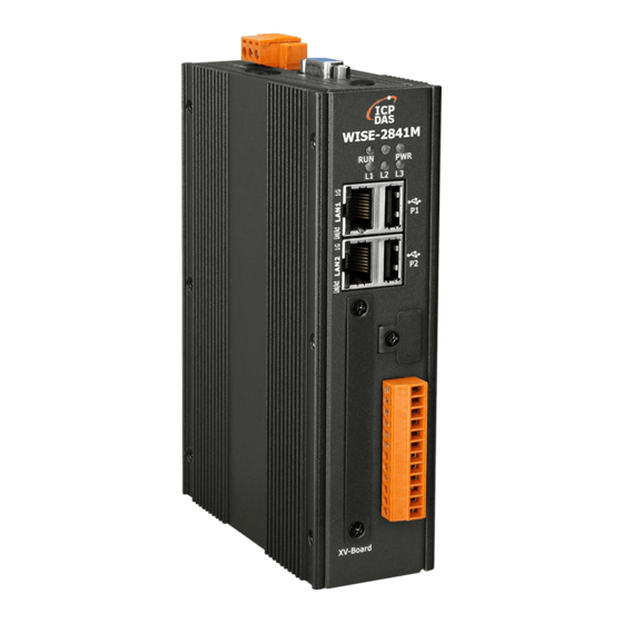
- Page 1 ICP DAS WISE User Manual for WISE-2841M Series [Version 1.0.0 - 2023/04/20]...
- Page 2 ICP DAS WISE User Manual Warning The information furnished by ICP DAS Co. Ltd. (hereinafter “ICP DAS”) is accurate and reliable to ICP DAS‟s best knowledge. ICP DAS reserves the right to change the content of this manual at any time without notice. Through the communication mechanisms provided by third-party companies (such as LINE, WeChat, Amazon Web Services, Microsoft Azure, IBM Bluemix), this controller can send the notification messages and information regarding this controller...
-
Page 3: Table Of Contents
ICP DAS WISE User Manual Table of Contents Introduction ..................... 15 Before Installation ................... 23 System Login ..................25 WISE Web Page Overview ..............27 System function area ..............28 Sub-function area ................. 32 Data review/System setting area ..........33 System and logic rule setting procedure ........ - Page 4 ICP DAS WISE User Manual AWS Platform Setting ..............120 Microsoft Azure Platform Setting ..........128 IBM Bluemix Platform Setting ............ 133 MQTT Setting ................137 IoTstar Connection Setting ............145 IoTstar Real-Time Data Sending Setting ........147 IoTstar Historical Data Sending Setting ........148 IoTstar Video Data Sending Setting ...........
- Page 5 ICP DAS WISE User Manual Appendix VII:The JSON format for the communication with IoT Platform . 317 Appendix VIII:WISE-2841M LED Indicators ..........321 Appendix IX:ICP DAS “IoTstar Trial” account application ......322 http://wise.icpdas.com...
- Page 6 ICP DAS WISE User Manual List of Figures Figure 1-1:WISE-2841M System Architecture ..........17 Figure 1-2:IO module support list ..............18 Figure 3-1:The password setting page for first time login WISE ....25 Figure 3-2:WISE Login page ............... 25 Figure 4-1:WISE home page (login as an Administrator) ......27 Figure 4-2:System Function Area (login as an Administrator) .....
- Page 7 ICP DAS WISE User Manual Figure 5-17:SNMP Setting Page ..............48 Figure 5-18:SNMP V3 Setting Page ............48 Figure 5-19:SNMP V3 User Setting Page ........... 49 Figure 5-20:SNMP V3 User Authentication & Encryption Setting Page ..49 Figure 5-21:VPN Setting Page ..............51 Figure 5-22:DDNS Setting Page ..............
- Page 8 ICP DAS WISE User Manual Figure 6-28:Select the model of the Modbus RTU Module ......75 Figure 6-29:Add the Modbus RTU Module manually ........75 Figure 6-30:Modbus RTU module List Operation Interface ......76 Figure 6-31:ICP DAS Modbus RTU module DI Channel Setting page ..77 Figure 6-32:ICP DAS Modbus RTU module DO Channel Setting page ..
- Page 9 ICP DAS WISE User Manual Figure 8-1:Amazon Web Services Setting page ........120 Figure 8-2:"Device Data Endpoint" Setting page of Amazon Web Services ......................121 Figure 8-3:Certificate and Key Download page of Amazon Web Services 122 Figure 8-4:"Thing ARN" page of Amazon Web Services ......123 Figure 8-5:Publish and Subscribe Setting page of Amazon Web Services 124 Figure 8-6:Publish Message Setting Page of Amazon Web Services ..
- Page 10 ICP DAS WISE User Manual Figure 9-1:Internal Register List Page ............154 Figure 9-2:Internal Register Setting page ..........155 Figure 9-3:Timer Status and Actions ............157 Figure 9-4:Timer List Page ................ 158 Figure 9-5:Timer Setting page (by assign value) ........158 Figure 9-6:Timer Setting page (by Internal Register) .........
- Page 11 ICP DAS WISE User Manual Figure 9-38:LINE Notify Chat Room Setting page (2) ....... 183 Figure 9-39:LINE Notify Chat Room Setting page (3) ....... 183 Figure 9-40:LINE Notify Chat Room Setting page (4) ....... 184 Figure 9-41:LINE Notify Chat Room Setting page (5) ....... 184 Figure 9-42:LINE Notify Chat Room Test Function ........
- Page 12 ICP DAS WISE User Manual Figure 10-10:AI Deadband Operation (< or <= a numerical value) .... 217 Figure 10-11:AI Deadband Operation (= a numerical value) ..... 217 Figure 10-12:AO condition setting page ............ 218 Figure 10-13:Discrete Input condition setting page ........219 Figure 10-14:Coil Output condition setting page ........
- Page 13 ICP DAS WISE User Manual Figure 10-48:Microsoft Azure Reset Variable action setting page ..... 246 Figure 10-49:IBM Bluemix Function Status action setting page ....247 Figure 10-50:IBM Bluemix Publish Message action setting page ....247 Figure 10-51:IBM Bluemix Reset Variable action setting page ....248 Figure 10-52:MQTT Broker Function action setting page ......
- Page 14 ICP DAS WISE User Manual Figure 15-5:Firmware Update (4) .............. 269 Figure 15-6:Firmware Update (5) .............. 269 Figure 16-1:Export/Import Setting page and the settings to be backed up 270 Figure 16-2:"Export Settings" and "Export Certificates" message windows ......................271 http://wise.icpdas.com...
-
Page 15: Introduction
ICP DAS WISE User Manual 1 Introduction WISE-2841M Advanced version IIoT Edge Controller is an Intelligent Web-based Multi-functions PAC controller designed by ICP DAS that functions as control units for use in remote logic control and monitoring in various industrial applications. WISE offers a user-friendly and intuitive HMI interface that allows you to implement control logic on controllers just a few clicks away;... - Page 16 ICP DAS WISE User Manual controller from the attack of password cracking. With the equipped VPN function, WISE-2841M can connect to devices in a specific secure network domain to completely isolated from the threats of information security outside. WISE-2841M provides supports in I/O functions. It supports XV-board; allows connections to I-7000 I/O modules, Modbus RTU Slave modules and Modbus TCP Slave modules together.
-
Page 17: Figure 1-1:Wise-2841M System Architecture
ICP DAS WISE User Manual Figure 1-1:WISE-2841M System Architecture WISE-2841M system features: IF-THEN-ELSE logic rules execution ability WISE-2841M equips with an IF-THEN-ELSE logic Rule Engine; it offers IF-THEN-ELSE rules for you to set up the logic content. After completing rule edition and downloading rules to the WISE controller, the Rule Engine will loop execute the rules in order under specific conditions. -
Page 18: Figure 1-2:Io Module Support List
ICP DAS WISE User Manual modules as XV-Board, I-7000 modules, M-7000 modules, (P)ET-7000 modules, WISE-7100 modules, WF-2000 modules and tM/DL/LC/IR/iSN series modules. In addition to these ICP DAS modules, WISE-2841M also allows to connect with devices that support Modbus RTU/TCP Slave protocol for I/O monitoring. The ability to connect with various types of I/O modules enables flexibility and scalability for system implementation and allows to meet various requirements from the clients that enable to find best solutions to meet the requirements. - Page 19 ICP DAS WISE User Manual the FTP server or the Email address for users, or user can actively download them from the FTP client utility or Web page for further administration management or data analysis. Internal Register (Perform Math formula, Retain Variable, String processing) WISE-2841M provides Internal Registers function;...
- Page 20 ICP DAS WISE User Manual The CGI command sending action can be added to the logic edition as part of logic control in response to specific events. The CGI command receiving function let WISE-2841M can receive the CGI command from others network devices.
- Page 21 ICP DAS WISE User Manual Active I/O Sending function In addition to the Modbus TCP/RTU Slave function that enables SCADA software (or HMI device) to poll the I/O channels value of the WISE controller, now WISE-2841M provide the function “Active I/O Sending” for users. Based on the “Active I/O Sending”...
- Page 22 ICP DAS WISE User Manual realtime I/O channel data, or a snapshot via the connected IP camera. Provide Telegram message sending function WISE-2841M supports to send Telegram messages to the Telegram personal account or group chat room. The Telegram message sending function can be triggered by IF-THEN-ELSE rules.
-
Page 23: Before Installation
ICP DAS WISE User Manual 2 Before Installation When WISE is powered on, please wait about one minute to complete the start-up procedure. When the “RUN” LED starts flashing, it represents the boot is complete, the connection can be started. Modify WISE's network settings to fit current network environment settings, and the default network settings of WISE is as follow: LAN1:DHCP... - Page 24 ICP DAS WISE User Manual modify the network setting to fit current network environment. More detailed setting information please refers to 5.2 Network Setting. (6) Save the settings and connect WISE to the network. http://wise.icpdas.com...
-
Page 25: System Login
ICP DAS WISE User Manual 3 System Login When connect to WISE webpage server via Web browser (IE 11 / Firefox 53 / Chrome 58 version or above are recommended), in order to get a better operation experience, 1280x1024 resolution is recommended. When connect to the WISE website for the first time, it will be required to set up the password for the system administrator. - Page 26 ICP DAS WISE User Manual User (Password is defined by Administrator) WISE provides 5 User accounts to login. Each User can access to perform the modification or review of the WISE settings (based on the authority the administrator pre-assigned), however, the User does not have the right to add or delete the settings of WISE.
-
Page 27: Wise Web
ICP DAS WISE User Manual 4 WISE Web Page Overview Users can login WISE by using Administrator, User or Guest accounts. Different WISE default home page will be displayed based on the different login account. If Administrator login into the system, the WISE default home page will be displayed as below, and will automatically read settings of the WISE to the webpage. -
Page 28: System Function Area
ICP DAS WISE User Manual 4.1 System function area System function area provides immediately access to the main functions of WISE, such as: system settings, system real-time information display, rule files management, etc, shown as below: Figure 4-2:System Function Area (login as an Administrator) System function area includes the following areas: A1. -
Page 29: Figure 4-7:Confirm To Clear Settings
ICP DAS WISE User Manual WISE in the nickname field for easy recognition. Figure 4-6:WISE Nickname setting “New” button allows resetting the settings of all parameters button and click on “OK”, the settings on and Rules. Click on WISE webpage on the browser will be cleared. If the user would like to clear the setting on WISE, then continue to click on “Save”... -
Page 30: Figure 4-10:Confirm To Logout (The Settings Are Saved)
ICP DAS WISE User Manual “Logout” button allows to log out the system, click on button and then click “OK” to logout the system. Figure 4-10:Confirm to logout (The settings are saved) If the settings are not saved to the WISE before performing logout, a warming message will appear as below: Figure 4-11:Confirm to logout (The settings are not saved) Please... -
Page 31: Figure 4-13:Real-Time Information List
ICP DAS WISE User Manual "estimate of the remaining days to log with this microSD" is for sensor data only, not include the image/video files. So if there are the IP cameras connect to WISE, the information will be inaccurate. ... -
Page 32: Sub-Function Area
ICP DAS WISE User Manual 4.2 Sub-function area Sub-function area will display detailed functions under the selected System function. The user could edit or review detailed function options in the Sub-function area. On the upper Sub-function area, the path of current function will be displayed to show the current function path. -
Page 33: Data Review/System Setting Area
ICP DAS WISE User Manual 4.3 Data review/System setting area Data review/System setting area allows to set system parameters and data review of WISE, the content of this area will be varied according to the selected sub-function. When the user login into the page as an Administrator, the Data review/System setting area of the Main Page will be the System Setting page, it will display all system setting information of the WISE as below: Figure 4-15:Data review/System setting area... -
Page 34: Figure 4-16:Data Review/System Setting Area (Login As User Or Guest)
ICP DAS WISE User Manual Figure 4-16:Data review/System setting area (login as User or Guest) http://wise.icpdas.com... -
Page 35: System And Logic Rule Setting Procedure
ICP DAS WISE User Manual 4.4 System and logic rule setting procedure When the Administrator login WISE, The System function toolbar includes the following 6 function options: System Setting Module Setting Logger Setting IoT Platform Setting ... -
Page 36: System Setting
ICP DAS WISE User Manual 5 System Setting System Setting includes 9 options: Time Setting, Network Setting, Account Setting, Security Setting, SNMP Setting, VPN Setting, DDNS Setting, Others Setting and COM Port Interface Setting. When you get into the System Setting page, the system settings information of this WISE will be displayed, as shown below. -
Page 37: Time Setting
ICP DAS WISE User Manual 5.1 Time Setting On the Time Setting page, it allows to set the time of WISE and Time Synchronization function. The setting interface is as below: Figure 5-2:Time Setting Page When get into this page, the system will read and display current time of the WISE. -
Page 38: Network Setting
ICP DAS WISE User Manual Follow the steps below to set up Time Synchronization Setting: i In the “Function Status” field, click “Enable” to enable the Time Synchronization function. ii In the “SNTP Time Server” field, input the IP address or domain name of the SNTP Time Server. -
Page 39: Figure 5-4:Network Setting Page
ICP DAS WISE User Manual Figure 5-4:Network Setting Page Each time when the user enters this page, it will read and display current network configuration (LAN) and port settings from the WISE. In the “Network Setting (LAN)” section, user can select the connection mode as “Obtain an IP address automatically (DHCP)”... -
Page 40: Account Setting
ICP DAS WISE User Manual Please note: If the connection mode is “Specify an IP address”, then you make modification to the IP address, the system will logout automatically and re-connect to the web page automatically based on the new setting. If the connection mode is “Obtain an IP address automatically (DHCP)”, the system may fail to re-connect to the web page because the IP address is changed. -
Page 41: Figure 5-6:Account Setting Page For User
ICP DAS WISE User Manual to administrator when it is in abnormal status. Once the password is forgotten or lost, WISE could also send an email with the passwords (Administrator account, User account, Guest account, Local FTP login and CGI Query Authentication) to administrator, for more detailed information, please refer to Appendix WISE provides 5 User accounts. -
Page 42: Security Setting
ICP DAS WISE User Manual The settings steps are as below: i. In the “User” filed, select the user which will be enabled. WISE provides 5 User accounts. ii. In the “Status” field, click the “Enable” items to enable the User account, then the Password setting field and the Permission setting field will be enabled. -
Page 43: Figure 5-8:Security Setting Page
ICP DAS WISE User Manual Figure 5-8:Security Setting Page Web Server Setting The WISE's web server uses the unencrypted HTTP protocol by default. User can replace it to the encrypted HTTPS protocol to protect the content of the data transmission. The port of the web server is also changeable. -
Page 44: Figure 5-10:Local Sftp Server Setting Page
ICP DAS WISE User Manual be set: Domain Name: To enable HTTPS mode, user must apply a domain name for the WISE controller in advance. SSL Certificate: To enable HTTPS mode, an SSL certificate is required for data encryption. User can manually import the files related to the SSL certificate he purchase, or directly apply for a certificate from “Let's Encrypt”... -
Page 45: Figure 5-11:Local Ftp Server Setting Page
ICP DAS WISE User Manual Local FTP Server Setting User can enable or disable the function of WISE's FTP server. After enable this functoin, he can connect to WISE FTP Server via FTP software to remotely retrieve event log or data log files from WISE. To enable this function, please check “Enable”... -
Page 46: Figure 5-13:Cgi Query Authentication Setting Page
ICP DAS WISE User Manual sending and CGI command receiving. In the CGI command receiving function, administrator can set a set of account and password in the “CGI Query Authentication Setting” section to protect the operation of the WISE, then WISE will only receive the CGI commands with this account and password information, perform the corresponding operations, and ignore other CGI commands that do not with this account and password information. -
Page 47: Snmp Setting
ICP DAS WISE User Manual the “Add” button in the List field, WISE provides three ways to set up the content of the Blacklist and Whitelist according to the network environment as “Single IP Address”, “Subnet” and “IP Address Range”. Please refer following. -
Page 48: Figure 5-17:Snmp Setting Page
ICP DAS WISE User Manual and V3 to work with the SNMP Network Management software for monitoring the system data and I/O module data. The SNMP Setting page allows you to enable or modify the settings of the SNMP function on the WISE. -
Page 49: Figure 5-19:Snmp V3 User Setting Page
ICP DAS WISE User Manual Figure 5-19:SNMP V3 User Setting Page vi. Key in the username in the “User Name” field. vii. Select “read-only” or “read-write” in the “Action Permission” field. viii. There are three levels of security options in the “Security Level” field, please refer to following. -
Page 50: Vpn Setting
ICP DAS WISE User Manual x. After complete the setting for all SNMP V3 user, click “Save” button to complete the SNMP settings. Please Note: The official website of WISE provides the WISE-2841M MIB file. User can download it from the WISE official website. 5.6 VPN Setting WISE provides the VPN (Virtual Private Nnetwork) service to protect WISE to avoid the malicious accessed by external devices and ensure the... -
Page 51: Figure 5-21:Vpn Setting Page
ICP DAS WISE User Manual Figure 5-21:VPN Setting Page Please follow the steps below for the VPN settings: i. In the “Function Status” field, check “Enable” to enable the VPN function. ii. In the “Server Settings” section, select the VPN service user want to use from the 4 connection types, then complete the setting for the connection and TCP/IP required by the service. -
Page 52: Ddns Setting
ICP DAS WISE User Manual 5.7 DDNS Setting WISE provides the Dynamic DNS service. The following figure illustrates the configuration interface: Figure 5-22:DDNS Setting Page Follow the steps below to set up Dynamic DNS service: i In the “Function Status” field, check “Enable” to enable the DDNS function. -
Page 53: Others Setting
ICP DAS WISE User Manual 5.8 Others Setting In Others Setting page, users can set up the decimal place number for the floating-point value displayed by WISE. The setting interface is as follows: Figure 5-23:Decimal Place Number Setting Page User can set up the decimal place number to 1~4. After the setting is completed, click the “Save”... -
Page 54: Figure 5-25:Com Port Interface Setting For Modbus Rtu Slave
ICP DAS WISE User Manual Modbus RTU Slave (Connect to HMI or SCADA ) Figure 5-25:COM Port Interface Setting for Modbus RTU Slave The settings steps are as below: i In the “Baudrate” field, select the Baudrate from the dropdown list, the Baudrate of WISE and HMI or SCADA have to be set the same. -
Page 55: Figure 5-26:Com Port Interface Setting For Dcon Master
ICP DAS WISE User Manual DCON Master (Connect to DCON modules) Figure 5-26:COM Port Interface Setting for DCON Master The settings steps are as below: i In the “Baudrate” field, select the Baudrate from the dropdown list, the Baudrate of WISE and DCON module have to be set the same. ii In the “Parity”... -
Page 56: Figure 5-27:Com Port Interface Setting For Modbus Rtu Master
ICP DAS WISE User Manual Modbus RTU Master (Connect to Modbus RTU slave devices) Figure 5-27:COM Port Interface Setting for Modbus RTU Master The settings steps are as below: i In the “Baudrate” field, select the Baudrate from the dropdown list, the Baudrate of WISE and Modbus RTU slave module have to be set the same. -
Page 57: Module Setting
ICP DAS WISE User Manual Module Setting Module setting page allows to perform settings of the I/O Modules and IP Cameras that are connected to the WISE. After getting into the setting page, the overview page will display current setting of the I/O Modules and IP Cameras that are connected to the WISE, shown as below: Figure 6-1:Module Setting Page Module Setting includes the following 3 setting options:... -
Page 58: Figure 6-2:Xv-Board Setting Page
ICP DAS WISE User Manual shown as follow: Please note: Each time WISE is allowed to connect to one XV-Board module only. Figure 6-2:XV-Board Setting Page Select the XV-Board that are connected to the WISE from the drop down list and click “Setting”, a window for setting up the parameters of XV-Board and its I/O channel will appear. -
Page 59: Figure 6-3:Xv-Board Di Channel Setting Page
ICP DAS WISE User Manual 6.1.1 XV-Board DI Channel Settings The XV-Board DI Channel Setting page is shown as follow (using XV107 as an example): Figure 6-3:XV-Board DI Channel Setting Page The settings are as follow: Channel Nickname: For user to define nicknames for each I/O channel, these nicknames will be displayed on the “Channel Status”... -
Page 60: Figure 6-4:Xv-Board Do Channel Setting Page
ICP DAS WISE User Manual Figure 6-4:XV-Board DO Channel Setting Page The settings are as follow: Nickname: For user to define nicknames for each I/O channel, these nicknames will be displayed on the “Channel Status” and “Rule Setting” pages. ... -
Page 61: Figure 6-5:Xv-Board Ai Channel Setting Page
ICP DAS WISE User Manual on the XV-Board will be copied to the DO channel. For example, when the “DI Status Mapping” is enabled on DO0, when the DI0 status is ON, DO0 will set to be ON, and when the DI0 status is OFF, DO0 will set to be OFF as well. -
Page 62: Remote I-7000/Dl Dcon Module Setting
ICP DAS WISE User Manual After all settings of the channels are completed, click “OK” button to return to XV-Board Setting page. 6.1.4 XV-Board AO Channel Settings The XV-Board AO Channel Setting page is shown as follow (using XV310 as an example): Figure 6-6:XV-Board AO Channel Setting Page The settings are as follow: ... -
Page 63: Figure 6-7:Remote I-7000/Dl Module Setting Page
ICP DAS WISE User Manual Figure 6-7:Remote I-7000/DL Module Setting Page The following section will give more information how to add and complete settings of I-7000/DL DCON modules. After all settings are completed, click “Save” button to save the changes. Please note: 1. -
Page 64: Figure 6-9:Set Up The Scanning Range For The I-7000/Dl Modules
ICP DAS WISE User Manual Figure 6-9:Set up the Scanning Range for the I-7000/DL modules iii. When the system is performing the scan, the address that are performing scan will be dynamically shown on the upper left side, please wait till the scan operation is completed. To stop the scan operation, click on “Cancel”... -
Page 65: Figure 6-12:Select The Actual I-7000/Dl Modules Connected
ICP DAS WISE User Manual Figure 6-12:Select the actual I-7000/DL modules connected 6.2.2 Add I-7000/DL DCON Module manually In addition to perform Scan operation to automatically add I-7000/DL DCON modules to the list, the user could also add the I-7000/DL DCON module manually one by one, the steps are as below: i. -
Page 66: I-7000/Dl Dcon Module List Operation Interface
ICP DAS WISE User Manual iv. Input the Nickname for the I-7000/DL DCON modules. v. Click to add the I-7000/DL DCON module to the list. After adding the I-7000/DL DCON module, click “Save” button to save the changes. Figure 6-15:Add the I-7000/DL Module manually 6.3 I-7000/DL DCON Module List Operation Interface After the I-7000/DL DCON modules are added to the I/O Module list via auto scan or manual work, the I-7000/DL DCON modules will be listed as... -
Page 67: Figure 6-17:I-7000/Dl Module Di Channel Setting Page
ICP DAS WISE User Manual module to upper order (decrease the index number (No.)). Move Down: Click the radio button in front of the I-7000/DL DCON module and click on “Move Down” to move the I-7000/DL DCON module to lower order (increase the index number (No.)) ... - Page 68 ICP DAS WISE User Manual The settings are as below: Nickname: For user to define nickname for the module and the I/O channels, these nicknames will be displayed on the “Channel Status” and “Rule Setting” pages. Description: The Description field provides a space for the user to make a brief description of this module.
-
Page 69: Figure 6-18:I-7000/Dl Module Do Channel Setting Page
ICP DAS WISE User Manual Figure 6-18:I-7000/DL Module DO Channel Setting page The settings are as below: Nickname: For user to define nickname for the module and the I/O channels, these nicknames will be displayed on the “Channel Status” and “Rule Setting” pages. ... -
Page 70: Figure 6-19:I-7000/Dl Module Ai Channel Setting Page
ICP DAS WISE User Manual I-7000/DL DCON Module List. Please Note: 1. To set up the Power On value of the DO channels on I-7000/DL DCON modules, please use DCON Utility to set the value. 2. The DO channels on I-7000/DL DCON modules do not offer Pulse Output function. -
Page 71: Figure 6-20:I-7000/Dl Module Ao Channel Setting Page
ICP DAS WISE User Manual already-adjusted value in the evaluation operation, and the AI value retrieved from the “Channel Status” page or Modbus Table via WISE would be the adjusted value. The default value for Maximum and Minimum is 0, it means the Scale function is disabled. -
Page 72: Remote Modbus Rtu Module Setting
ICP DAS WISE User Manual Please note: To set up the Power On value of the AO channels on I-7000/DL DCON modules, please use DCON Utility to set the value. 6.4 Remote Modbus RTU Module Setting WISE allows connections to ICP DAS M-7000/tM/DL/LC/IR/iSN modules and general Modbus RTU Modules. -
Page 73: Figure 6-22:The "Scan" Button To Search Icp Das Module
ICP DAS WISE User Manual Figure 6-22:The “Scan” button to search ICP DAS module ii. When the Scan page appears, input the starting address and the ending address of the Modbus address that are going to perform scan. Click on “Scan”, the system will start to scan the ICP DAS modules that match the settings previously set, to cancel the scan, and click on “Cancel”. -
Page 74: Figure 6-25:The Icp Das Module List After Scan Operation
ICP DAS WISE User Manual Figure 6-25:The ICP DAS module List after Scan operation Figure 6-26:Select the actual ICP DAS modules 6.4.2 Add ICP DAS module or Modbus RTU Module manually In addition to perform Scan operation to automatically add M-7000/tM/DL/LC/iSN modules to the list, the user could also add the ICP DAS M-7000/tM/DL/LC/IR/iSN modules or Modbus RTU modules manually one by one, the steps are as below:... -
Page 75: Modbus Rtu Module List Operation Interface
ICP DAS WISE User Manual Figure 6-27:Set up the No. and Address of the Modbus RTU modules iii. Select the module name: For ICP DAS modules, the user could select the default model name from the dropdown list. Please input the nickname for other Modbus RTU modules manually. -
Page 76: Figure 6-30:Modbus Rtu Module List Operation Interface
ICP DAS WISE User Manual Figure 6-30:Modbus RTU module List Operation Interface Through the operations of “Setting”, “Move Up”, “Move Down”, “Copy” and “Remove” functions, user can set up the parameters or adjust the arrangement order for each Modbus RTU module in the list. Please refer to the description of “6.3 I-7000/DL DCON Module List Operation Interface”... -
Page 77: Figure 6-31:Icp Das Modbus Rtu Module Di Channel Setting Page
ICP DAS WISE User Manual Figure 6-31:ICP DAS Modbus RTU module DI Channel Setting page The settings are as below: Nickname: For user to define nickname for the module and the I/O channels, these nicknames will be displayed on the “Channel Status”... -
Page 78: Figure 6-32:Icp Das Modbus Rtu Module Do Channel Setting Page
ICP DAS WISE User Manual After all settings of the DI channels are completed, continue the configuration of other channels, and after all channel settings are completed, click “OK” button to save the changes and return to Modbus RTU Module List. Please Note: For M-7000 modules, the counting mode of the DI channel counter is Falling. -
Page 79: Figure 6-33:Icp Das Modbus Rtu Module Ai Channel Setting Page
ICP DAS WISE User Manual configuration of other channels, and after all channel settings are completed, click “OK” button to save the changes and return to Modbus RTU Module List. Please Note: 1. To set up the Power On value of the DO channels on M-7000/tM/DL/LC/IR/iSN modules, please use DCON Utility to set the value. -
Page 80: Figure 6-34:Icp Das Modbus Rtu Module Ao Channel Setting Page
ICP DAS WISE User Manual temperature units can be set as degree Celsius or degree Fahrenheit. Type: Select the input signal type of the AI channel from the dropdown list. Scale: Please refer to “6.3.3 The AI channel setting for I-7000/DL module”... -
Page 81: Figure 6-35:Modbus Rtu Module Coil Output Setting Page
ICP DAS WISE User Manual After all settings of the AO channels are completed, continue the configuration of other channels, and after all channel settings are completed, click “OK” button to save the changes and return to Modbus RTU Module List. Please note: To set up the Power On value of the AO channels on M-7000/tM/DL/LC/IR/iSN modules, please use DCON Utility to set the value. - Page 82 ICP DAS WISE User Manual Scan Rate: Input the time interval for WISE to periodically retrieve the I/O channel data of this Modbus RTU module, the setting range will be 0 ~ 65535 seconds. Polling Timeout: The time interval for WISE to send command to the Modbus RTU module and wait for the response, the unit will be ms.
-
Page 83: Figure 6-36:Coil Output Setting Example For Modbus Rtu Module
ICP DAS WISE User Manual 04500、04501、04502 and 04503. Figure 6-36:Coil Output Setting Example for Modbus RTU module To modify the settings of starting address, quantity or Read/Write authority, please click on the setting block and input the setting. Click “OK” for modification or click “Remove” to remove the setting. -
Page 84: Figure 6-37:Modbus Rtu Module Discrete Input Setting Page
ICP DAS WISE User Manual completed, continue the configuration of other channel, and after all channel settings are completed, click “OK” button to save the changes and return to Modbus RTU Module List. 6.5.6 The Discrete Input Setting of Modbus RTU Module The Modbus RTU Module Discrete Input Setting page is shown as follow: Figure 6-37:Modbus RTU module Discrete Input Setting page... -
Page 85: Figure 6-38:Discrete Input Setting Example For Modbus Rtu Module
ICP DAS WISE User Manual the local Modbus address of WISE to keep the Discrete Input data.). Figure 6-38 shows an example about Discrete Input setting for a Modbus RTU module. The starting Modbus address of the Discrete Input block is 10020(10000 + 20), it requires to set 6 continuous Discrete Input data in the setting. -
Page 86: Figure 6-39:Modbus Rtu Module Input Register Setting Page
ICP DAS WISE User Manual After all settings of the Discrete Input of the Modbus RTU module are completed, continue the configuration of other channel, and after all channel settings are completed, click “OK” button to save the changes and return to Modbus RTU Module List. 6.5.7 The Input Register Setting of Modbus RTU Module The Modbus RTU Module Input Register Setting page is shown as follow:... - Page 87 ICP DAS WISE User Manual detailed information. In this case please select “Input Register (3x)”. Start Address: Allows setting up the starting address of Input Register (3x) on the Modbus RTU module you would like to retrieve. Data Number: After finishing the Start Address setting, specify the Data Number, it is the number of Input Register data you would like to retrieve from the Start Address.
-
Page 88: Figure 6-40:Input Register Setting Example For Modbus Rtu Module
ICP DAS WISE User Manual Figure 6-40 shows an example about Input Register setting for a Modbus RTU module. The starting Modbus address of the Input Register block is 30010(30000 + 10), it requires to set 3 continuous Input Register data in the setting, and the data type is “32-bit Floating Point”. - Page 89 ICP DAS WISE User Manual If the user wants to assign a Nickname for the address blocks, the user can click on the “Nickname Setting” tab, and then input the Nickname for each address block. The Nickname will be shown in the “Channel Status”...
-
Page 90: Figure 6-41:Modbus Rtu Module Holding Register Setting Page
ICP DAS WISE User Manual Figure 6-41:Modbus RTU module Holding Register Setting page The settings are as follow: Data Model: WISE offers 4 Data Model selections to match the Modbus RTU module configuration. Please refer to the section “6.5.5 The Coil Output Setting of Modbus RTU Module”... -
Page 91: Figure 6-42:Holding Register Setting Example For Modbus Rtu Module
ICP DAS WISE User Manual If users select “32-bit Signed Long”, “32-bit Unsigned Long”, or “32-bit Floating Point”, the option “Inverse (Big Endian)” will appear. Enable “Inverse (Big Endian)” to receive the data in Big Endian format correctly. After finishing the “Start Address”, “Data Number”, and “Type” setting;... - Page 92 ICP DAS WISE User Manual To modify the settings of the starting address, quantity or Read/Write authority, please click on the setting block to perform the modification. The user could also modify Type, Scale Ratio, Offset, and Read/Write authority on this interface. The Scale Ratio setting and Offset setting allows to transform the Holding Register value in this block by linear transformation.
- Page 93 ICP DAS WISE User Manual After all settings of the Holding Register of the Modbus RTU module are completed, continue the configuration of other channel, and after all channel settings are completed, click “OK” button to save the changes and return to Modbus RTU Module List. Please note: The number of Modbus address setting blocks will affect the data update rate for the Modbus RTU/TCP module.
-
Page 94: Remote Modbus Tcp Module Setting
ICP DAS WISE User Manual 6.6 Remote Modbus TCP Module Setting WISE allows connections ICP DAS (P)ET-7000/WISE-7100/ WF-2000/IR/DL modules and general Modbus TCP Modules. Through Modbus TCP protocol, it enables to read or write 4 types of Modbus data (Coil Output, Discrete Input, Input Register and Holding Register) from the Modbus TCP modules. -
Page 95: Modbus Tcp Module List Operation Interface
ICP DAS WISE User Manual Figure 6-44:Set up the Model/Name of the Modbus TCP Module iv. Click to add the Modbus TCP module to the list After adding the Modbus TCP module, click “Save” button to save the changes. Figure 6-45:Add the Modbus TCP Module manually 6.7 Modbus TCP Module List Operation Interface After the (P)ET-7000/WISE-7100/WF-2000/IR modules or Modbus TCP modules are added to the I/O Module list via manual work, the Modbus... -
Page 96: Ip Camera Setting
ICP DAS WISE User Manual arrangement order for each Modbus TCP module in the list. Please refer to the description of “6.3 I-7000/DL DCON Module List Operation Interface” for detail. After all settings are completed, click “Save” button to save the changes. About the setting of the I/O channel of ICP DAS (P)ET-7000/ WISE-7100/WF-2000/IR/DL modules and Modbus TCP modules, please input the value for the IP, Port and NetID parameters for the Modbus TCP... -
Page 97: Figure 6-47:Ip Camera Setting Page
ICP DAS WISE User Manual The setting page is shown as below: Figure 6-47:IP Camera Setting Page Please Note:One WISE-2841M controller allows connections to at most 12 IP Cameras. 6.8.1 Set Connection Network Interface and Video Function i. Select LAN 1 or LAN2 to be the connection network interface to connect with IP Cameras. -
Page 98: Ip Camera List Operation Interface
ICP DAS WISE User Manual Figure 6-49:Set up the Model Name of the IP Cameras iv. Click to add the IP Camera to the list. After adding the IP Camera, click “Save” button to save the changes. Figure 6-50:Add the IP Cameras 6.9 IP Camera List Operation Interface After the ICP DAS iCAM IP Cameras are added to the IP Camera list via manual work, the IP Cameras will be listed as below:... -
Page 99: Figure 6-52:Icam Ip Camera Setting Page
ICP DAS WISE User Manual order (increase the index number (No.)). Copy: To copy the settings of a pre-set iCAM IP Camera to the new iCAM IP Camera, please click the radio button in front of the pre-set iCAM IP Camera and then click on “Copy”, a new iCAM IP Camera (in sequence) will be added to the list and the settings of the old iCAM IP Camera will be copied to this newly added iCAM IP Camera. - Page 100 ICP DAS WISE User Manual IP: Enter the IP address of the IP Camera for the connection. Port: Enter the Port number of the IP Camera for the connection. Authentication: Because IP Camera requires account and password validation, please enter the login ID and Password of the IP Camera in the “Authentication”...
-
Page 101: Figure 6-53:Icam Ip Camera Osd Message Setting Page
ICP DAS WISE User Manual Figure 6-53:iCAM IP Camera OSD Message Setting page Input a name in the “Nickname” field and you could also input the description of this OSD message in the “Description” field. Enter the content of the OSD message in the “Content” field. WISE provides the “Real-time variable editor”... - Page 102 ICP DAS WISE User Manual The number of characters that can be displayed is depended on the resolution setting of the IP Camera. If the OSD message cannot be displayed completely, please reduce the character number of the message. After all settings of the IP Camera are completed, click “OK” button to save the changes and return to IP Camera List.
- Page 103 ICP DAS WISE User Manual Camera's Snapshot event setting first, enable the WISE's Timer setting later, then complete the WISE's IF-THEN-ELSE rule setting with Timer and Snapshot event for periodic recording. 2. Snapshot for Motion Detection: Please complete the iCAM IP Camera's Snapshot setting first, the trigger source is Motion Detection.
- Page 104 ICP DAS WISE User Manual 6.9.3 The Path of the files sent back by IP Camera After completing the settings of WISE and iCAM IP Cameras, the Image/Video files captured by iCAM IP Cameras will be sent back and stored in WISE. If the user enables the “File Transfer” function as described in section 6.9.1, the Image files and Video files will also be uploaded to remote FTP server of the manage center.
-
Page 105: Logger Setting
ICP DAS WISE User Manual 7 Logger Setting The Logger Setting function of the WISE provides recording of the I/O channel data from I/O modules. It includes I/O Module Data Logger and User-Defined Data Logger. The I/O Module Data Logger provides users to quickly record the data of all I/O modules and Internal Registers of WISE. -
Page 106: I/O Module Data Logger Setting
ICP DAS WISE User Manual 7.1 I/O Module Data Logger Setting The I/O Module Data Logger provides users to quickly record the data of all I/O modules and Internal Registers of WISE. On the I/O Module Data Logger Setting page, the user could enable the Data Logger if required. The setting page is shown as below: Figure 7-1:I/O Module Data Logger Setting Page Follow the steps below:... -
Page 107: Figure 7-2:The Format Of Record Data
ICP DAS WISE User Manual log content format will be like this: 2013/06/01,12:35:00,XXXX,…,…,…,Period Time information The record for all I/O Specify the data log is based on the setting of channel data and Period recording (Period) “Time Format” field. Internal Register. or Event trigger recording (Event). -
Page 108: Figure 7-3:Ftp Server Selecting And Setting Page
ICP DAS WISE User Manual Figure 7-3:FTP server selecting and setting page “7.5 FTP Server Please refer to Setting” section for detail. If you select “Do not upload to any FTP Server”, WISE will not send the data logger file to any FTP Server. x. -
Page 109: User-Defined Data Logger
ICP DAS WISE User Manual Figure 7-4:Email selecting and setting page Please refer to “9.4 Email Setting” section for detail. If you select “Do not send via Email”, WISE will not send the data logger file to any Email address. xi. -
Page 110: Figure 7-5:User-Define Data Logger List Interface
ICP DAS WISE User Manual Figure 7-5:User-Define Data Logger List Interface After clicking the “Add new User-Defined Data Logger”, a setting page of User-Defined Data Logger will appear. Figure 7-6:User-Define Data Logger Setting Page http://wise.icpdas.com... -
Page 111: Figure 7-7:The Setting Interface Of Real-Time Variable Editor
ICP DAS WISE User Manual Input a name in the “Nickname” field and you could also input the description of this User-Defined Data Logger in the “Description” field. About the setting of “Folder Name”, “Log Interval”, “Time Format”, “File Length”, “CSV Header”, “UTF-8 BOM”, “FTP Server” and “Email”... -
Page 112: Mqtt Data Logger Setting
ICP DAS WISE User Manual value encoded string will be displayed as below for user to check if the setting is appropriate (please refer to the figure as below). Figure 7-8:The view interface of Real-time Variable Editor After all settings are completed, click “OK” button to return to the User-Defined Data Logger list page. -
Page 113: Event Logger Setting
ICP DAS WISE User Manual Figure 7-9:MQTT Data Logger Setting page Follow the steps below: i In the “Function Status” field, click “Enable” to enable the MQTT Data Logger.。 ii About the setting of “Time Format”, “File Length”, “UTF-8 BOM”, “FTP Server”... -
Page 114: Ftp Server Setting
ICP DAS WISE User Manual keep going periodically. There are five options: “Disable”, “Once an hour”, “Once a day”, “Once a week” and “Once a month”. ii If user selects “Once a day”, “Once a week” or “Once a month”, please select the “Upload Timing”... -
Page 115: Figure 7-12:Ftp Server Setting Page
ICP DAS WISE User Manual Figure 7-12:FTP Server Setting page Input a name in the “Nickname” field and you could also input the description of this FTP Server in the “Description” field. In the “Server Address” and “Server Port” field, input the IP Address (or domain name) and Port number of the remote FTP Server. -
Page 116: The Path Of Data Log File
ICP DAS WISE User Manual FTP Server and then click “Copy”, a new remote FTP Server (in sequence) will be added to the list and the settings of the old remote FTP Server will be copied to this newly added remote FTP Server. xiii To remove a pre-set remote FTP Server, please click the radio button in front of the pre-set remote FTP Server and then click “Remove”. - Page 117 ICP DAS WISE User Manual ∟0208 Data files be sorted by day. ∟0208_00.csv ∟0208_01.csv ∟0209_10.csv The data file which is in using currently or is waiting for the upload operation. ∟EventLog (The folder for Event Logger file) ∟201502 Data files be sorted by year and month ∟Uploaded ...
- Page 118 ICP DAS WISE User Manual ∟0208_23.csv ∟0209_00.csv ∟0209_01.csv … ∟0209_09.csv ∟EventLog ( The folder for Event Logger file ∟201502 Data files be sorted by year and month ∟0207.csv ∟0208.csv ∟0209.csv Please note: If the remote FTP server receives log files from more than one WISE controller, please set different nickname to each WISE.
-
Page 119: Iot Platform Setting
ICP DAS WISE User Manual 8 IoT Platform Setting The IoT Platform Setting function of the WISE allows to build a connection to Amazon Web Services, Microsoft Azure or IBM Bluemix directly. It can also connect to MQTT Brokers. Based on the IoT Platform Setting function, WISE can publish the I/O channel data of the Sensors and I/O modules that are connected to WISE to the IoT Cloud Platform for future data analysis, and receive the command message from IoT Cloud Platform to trigger the... -
Page 120: Aws Platform Setting
ICP DAS WISE User Manual 8.1 AWS Platform Setting WISE provides the ability to connect to Amazon Web Services IoT Cloud platform. Because the setting of AWS platform is more complicated, this chapter only describe the setting that need to be set on WISE controller. For the complete connection setting between WISE and AWS platform, please to refer to the user manual of “ICP DAS WISE Monitoring IoT Kit - Amazon AWS IoT Starter Kit”. -
Page 121: Figure 8-2:"Device Data Endpoint" Setting Page Of Amazon Web Services
ICP DAS WISE User Manual Figure 8-2:"Device Data Endpoint" Setting page of Amazon Web Services In the “Device Certificate”, “Private Key” and “Root CA Certificate” fields, import the certificate and key generated from the AWS platform. Following is the page for the download of the certificate and key WISE need from AWS platform: http://wise.icpdas.com... -
Page 122: Figure 8-3:Certificate And Key Download Page Of Amazon Web Services
ICP DAS WISE User Manual Figure 8-3:Certificate and Key Download page of Amazon Web Services In the “Thing ARN” field, enter the information of “Thing ARN” set by AWS platform. Following is the page for the “Thing ARN” WISE need from AWS platform: http://wise.icpdas.com... -
Page 123: Figure 8-4:"Thing Arn" Page Of Amazon Web Services
ICP DAS WISE User Manual Figure 8-4:"Thing ARN" page of Amazon Web Services In the “Client ID” field, WISE will provide a default string (with the format of “WISE-serial number”) as the unique client ID for the WISE, and user can change this string according to his requirement. The client ID must be unique. -
Page 124: Figure 8-5:Publish And Subscribe Setting Page Of Amazon Web Services
ICP DAS WISE User Manual “Topic Prefix” setting to distinguish the Publish Topic/Subscribe Topic setting of each WISE controllers. viii After press the “Export” button in the “Export Policy File” field, WISE will generate the policy JSON file required by AWS platform according to the current settings. -
Page 125: Figure 8-6:Publish Message Setting Page Of Amazon Web Services
ICP DAS WISE User Manual Figure 8-6:Publish Message Setting Page of Amazon Web Services xii Input a name in the “Nickname” field and you could also input the description of this Publish Message in the “Description” field. xiii In the “Message Type” field, select the “Channel Data” to prepare a Publish Message with the I/O channel value. -
Page 126: Figure 8-7:"User-Defined Data" Setting Page Of Amazon Web Services
ICP DAS WISE User Manual xiv If the user selects “User-Defined Data” in “Message Type” field, the interface will be changed to free-style editing mode. So the user can edit the content of the message by himself via the editor. The interface is shown as below. -
Page 127: Figure 8-8:Subscribe Topic Setting Page Of Amazon Web Services
ICP DAS WISE User Manual xvi After complete all settings of Publish Message, please click “OK” button to add the Publish Message to the Publish Message List. xvii Click the “Subscribe” tab to edit the Subscribe Topic. The interface is shown as below: Figure 8-8:Subscribe Topic Setting Page of Amazon Web Services xviii Input a name in the “Nickname”... -
Page 128: Microsoft Azure Platform Setting
ICP DAS WISE User Manual Figure 8-9:Receive messages in JSON format of Amazon Web Services xx If the user selects “User-Defined Data” in “Message Type” field, the interface will be converted to free-style editing mode, and user can edit the Topic for the subscribe message by himself. He can also set the “Message Format”... -
Page 129: Figure 8-10:Microsoft Azure Setting Page
ICP DAS WISE User Manual Figure 8-10:Microsoft Azure Setting page Follow the steps below: Check “Enable” in the “Function Status” field to enable the connection to Microsoft Azure IoT Cloud Platform. ii Select “Connection Type” as “IoT Hub” or “IoT Hub DPS”. iii If “IoT Hub”... -
Page 130: Figure 8-11:Sas Token Generating Interface On Azure Iot Explorer
ICP DAS WISE User Manual Figure 8-11:SAS Token generating interface on Azure IoT Explorer iv If “IoT Hub DPS” is selected, get “DPS Endpoint”, “DPS ID Scope”, “Registration ID” and “Symmetric Key” parameters from the IoT Hub Device Provisioning Service(DPS) function page on the Azure platform. -
Page 131: Figure 8-12:Microsoft Azure Publish/Subscribe Setting Page
ICP DAS WISE User Manual status. viii The lower half section on the Microsoft Azure Setting Page is for the Publish Message and Subscribe Topic setting. User can click the tab of “Publish” or “Subscribe” to edit the Publish Message and Subscribe Topic. -
Page 132: Figure 8-14:"User-Defined Data" Setting Interface Of Microsoft Azure
ICP DAS WISE User Manual Message will be packaged in JSON format; if the “JSON” is not selected, the content of the Publish Message will only include the I/O channel value. (For the I/O Channel information in JSON Format, please refer to Appendix VII for more details.) The user can select “User-Defined Data”... -
Page 133: Ibm Bluemix Platform Setting
ICP DAS WISE User Manual Figure 8-15:Microsoft Azure Subscribe Topic setting page xv In the “Variable Name” field, user can input the name of the variable which is defined in the message of the Subscribe Topic. After completing the settings, click the “Add” button to add the variable. For the message the WISE receives from Microsoft Azure is based on JSON format, the WISE will get the corresponding value of the variable from the received message. -
Page 134: Figure 8-16:Ibm Bluemix Setting Page
ICP DAS WISE User Manual Figure 8-16:IBM Bluemix Setting page Follow the steps below: Check “Enable” in the “Function Status” field to enable the connection to IBM Bluemix IoT Cloud Platform. ii In the “Organization ID”, “Device Type”, “Device ID” and “Device Authentication Token”... -
Page 135: Figure 8-17:Ibm Bluemix Subscribe Message Setting Page
ICP DAS WISE User Manual WISE and IBM Bluemix. The “keep alive interval” enables IBM Bluemix to detect if the connection to the WISE is no longer available without having to wait for the long TCP/IP timeout. iv The value in “Periodical Publish Interval” field defines the time interval to automatically and periodically send the Publish Messages which are with the “Periodical Publish”... - Page 136 ICP DAS WISE User Manual which WISE receives: "Target":"door", "Action":"open", "Timestamp":"2016/10/17 15-17-22" In this example, the “Target” and “Action” variable setting will be performed first. Each time when the WISE receives the message, it will retrieve the corresponding value for the “Target” and “Action” variables from the message.
-
Page 137: Mqtt Setting
ICP DAS WISE User Manual 8.4 MQTT Setting WISE provides complete MQTT Client function. The MQTT Client can connect with two MQTT Brokers concurrently. In order to enable (Maximum) the MQTT Client function, user has to complete the setting of the WISE‟s Publish Topic and its message content with the MQTT Brokers, and also the setting of the WISE‟s Subscribe Topics. -
Page 138: Figure 8-19:Mqtt Broker Parameter Setting Page
ICP DAS WISE User Manual Figure 8-19:MQTT Broker Parameter setting page In the Broker parameters setting page, you can input the name of the Broker in the “Nickname” field and you could also input the description of this Broker in the “Description” field. Check “Enable”... - Page 139 ICP DAS WISE User Manual connect to the Broker or not. If the Broker does not require Client ID for the connection, this field can be ignored. If the SSL/TLS encryption mechanism is required for the connection between the Broker and the WISE via MQTT, click the “Enable”...
-
Page 140: Figure 8-20:Publish Message And Subscribe Topic Setting Page
ICP DAS WISE User Manual Publish Topic/Subscribe Topic setting of each WISE controllers. xv The lower half area of the MQTT Broker Setting Page is for the Publish Message and Subscribe Topic setting. User can click the “Publish” tab or “Subscribe” tab on the right-top corner of “Publish &... -
Page 141: Figure 8-22:Publish User-Defined Message Setting Page
ICP DAS WISE User Manual xvii Input a name in the “Nickname” field and you could also input the description of this Publish Message in the “Description” field. xviii In the “Message Type” field, select the “Channel Data” to prepare a Publish Message with the I/O channel value. -
Page 142: Figure 8-23:Mqtt Subscribe Setting Page
ICP DAS WISE User Manual Service) setting for the Publish Message. xx In the “Retain” field, user can click the “Enable” checkbox to keep the Publish Message in the Broker. xxi The timing to publish message is set in the “Auto Publish” field, there are two options: “When the I/O channel data changed and the variation exceeds xxx”... -
Page 143: Figure 8-25:Mqtt Topic Import/Export Setting Page
ICP DAS WISE User Manual “Description” field. In the “Topic” field, user can input the content of the Subscribe Topic. After completing all settings of Subscribe Topic, please click “Add” button to add the Subscribe Topic to the Subscribe Topic List. The value of the Subscribe Topic can be used in the IF-THEN-ELSE logic evaluation, and also be recorded in the MQTT Data Logger. -
Page 144: Figure 8-26:The Export Of Mqtt Topic
ICP DAS WISE User Manual collect all topics into the “topics.csv” file. The format of the “topics.csv” file is “The_nickname_of_Topic, Topic message”. Please refer to the following figure: Figure 8-26:The Export of MQTT Topic To use the Topic Import function, please prepare a document with the same format as “The_nickname_of_Topic, Topic message”. -
Page 145: Iotstar Connection Setting
ICP DAS WISE User Manual 8.5 IoTstar Connection Setting The section is for user to complete the connection setting between WISE and IoTstar or “ICP DAS IoTstar Trial Service”. Please follow the steps below for the setting: i Click “Enable” of the “Function Status” field to enable the connection to IoTstar. -
Page 146: Figure 8-29:Iotstar Connection Setting Page(2)
ICP DAS WISE User Manual refer to the instructions in Appendix IX: ICP DAS “IoTstar Trial” account application. Figure 8-29:IoTstar Connection Setting Page(2) iii After all settings are completed, click “Save” button to save the changes. After download the setting to WISE, WISE will connect to IoTstar, and the user can review the current connection status between WISE and IoTstar through the information displayed in the “Connection Status”... -
Page 147: Iotstar Real-Time Data Sending Setting
ICP DAS WISE User Manual 8.6 IoTstar Real-Time Data Sending Setting IoTstar can receive the real-time I/O data uploaded by WISE, and import the data into the database it created. The setting page is shown as below: Figure 8-31:IoTstar Real-Time Data Sending Setting page Follow the steps below: In the “Function Status”... -
Page 148: Iotstar Historical Data Sending Setting
ICP DAS WISE User Manual the Real-Time Data Table that IoTstar creates for the WISE (Please refer to Appendix VI of IoTstar User Manual). These names can be used later for further query operations of the Database. Figure 8-32:Channel Names of Realtime data table of IoTstar database iv After all settings are completed, click “Save”... -
Page 149: Figure 8-34:Iotstar Video Data Sending Setting Page (1)
ICP DAS WISE User Manual and perform the following actions: Save the event to trigger image/video recording, the event time, and the path to store image/video files into the database for further use. With IoTstar Dashboard Service package, users can build their own dashboard, and use “Video Event List”... -
Page 150: Iotstar Bot Service Message Setting
ICP DAS WISE User Manual of the tabs: “IP Camera”, “Sendbox” and “CGI Server” at the right-upper corner of the Video Data Sending Setting page. ii To send the desired files, please specify and click on the radio button of the file source, and click the “Setting”... -
Page 151: Figure 8-36:Iotstar Bot Service Message Setting Page (1)
ICP DAS WISE User Manual Figure 8-36:IoTstar Bot Service Message Setting page (1) Follow the steps below: Click “Add new message”, the Bot Service Message Setting page will appear as following: Figure 8-37:IoTstar Bot Service Message Setting page (2) ii Input name in the “Name” field and you could also input the description of this LINE message in the “Description”... -
Page 152: Advanced Setting
ICP DAS WISE User Manual 9 Advanced Setting Advanced Setting provides additional features and allows you to perform more setting on the WISE. Click on the Advanced Setting button, a column of buttons will appear on the left of the page: ... - Page 153 ICP DAS WISE User Manual 64-bit Unsigned Long 64-bit Double The data on the registers or each bit of the data can be read and evaluated in IF Condition, and be written or calculated after performing a THEN/ELSE Action.
-
Page 154: Figure 9-1:Internal Register List Page
ICP DAS WISE User Manual the list. (If the data type is Numeric, the default setting is 0, and if the data type is String, the default setting is Null.) iv Repeat steps i~iii to complete settings of all Internal Register. Figure 9-1:Internal Register List Page v To modify the settings of a pre-set Internal Register, please click on the radio button in front of the Internal Register, and then click on... -
Page 155: Figure 9-2:Internal Register Setting Page
ICP DAS WISE User Manual Figure 9-2:Internal Register Setting page vii If users need to perform math operations, check “Enable” in the Formula Setting section and edit math formula in the “Content of Formula” field. Users can select the “Interface”, “Module” and “Channel”... -
Page 156: Timer Setting
ICP DAS WISE User Manual Please note: Do not modify the channel value encoded string when you are editing the formula. It may cause failures when WISE reads the channel value. In addition, click the “Verifying” button could check the result of the formula. -
Page 157: Figure 9-3:Timer Status And Actions
ICP DAS WISE User Manual Stop Not Timeout Timeout Timer Status Timer Period Timer Action Start Pause Resume Reset Figure 9-3:Timer Status and Actions Follow the following steps: Input the nickname of the timer in the “Nickname” field. Specify the initial status of the timer from the dropdown list of the “Initial Status”... -
Page 158: Figure 9-4:Timer List Page
ICP DAS WISE User Manual Figure 9-4:Timer List Page v Repeat steps i~iv to complete settings of all Timers. vi To modify the settings of a pre-set timer, please click on the radio button in front of the timer, and then click on “Setting” to modify the settings. -
Page 159: Schedule Setting
ICP DAS WISE User Manual will be added to the list and the settings of the old Timer will be copied to this newly added Timer. x To remove a pre-set Timer, please click the radio button in front of the pre-set Timer and then click “Remove”. -
Page 160: Figure 9-8:Calendar Mode Of Schedule Setting
ICP DAS WISE User Manual Figure 9-8:Calendar mode of Schedule setting (b.) In the “Time Range(s)” section, click “Add” to add new Time Range of this schedule. Select the start time and the end time from the dropdown list. User can also enable the “Hourly” option for the “Time Range”... -
Page 161: Figure 9-9:Repeat Mode Of Schedule Setting
ICP DAS WISE User Manual Fridays to be “In Range”, and Saturdays and Sundays to be “Out of Range”, that is, the operations will be executed during “Select Weekend” weekdays only. On the contrary, the button is for you to set all Saturdays and Sundays to be “In Range”, and all Mondays to Fridays to be “Out of Range”, that is, the operations will be executed during weekends only. -
Page 162: Email Setting
ICP DAS WISE User Manual iv Click on “OK” to confirm the setting and leave the setting page. v Repeat steps i~iv to complete settings of all Schedules. vi To modify the settings of a pre-set Schedule, please click on the radio button in front of the Schedule, and then click on “Setting”... -
Page 163: Figure 9-11:Email Setting Page (Name & Description)
ICP DAS WISE User Manual Figure 9-11:Email setting page (Name & Description) In the “SMTP Server” field, enter the IP or the domain name of the SMTP server; or select the SMTP server from the dropdown list. In the dropdown list, WISE provide four public SMTP servers for selection as below: ... -
Page 164: Figure 9-13:Email Setting Page (Email Address)
ICP DAS WISE User Manual Enter the sender‟s email address in the “Sender Email Address” field. In the “Receiver Email Address” section, click on “Add” to add the receiver‟s email address. At least one email address has to be entered. The number of the receiver's email addresses is unlimited. -
Page 165: Snmp Trap Setting
ICP DAS WISE User Manual “Send” in the “Email Setting Test” section, then WISE will send a test Email to the receivers‟ email addresses. xv Click on “OK” to confirm the setting and return to the Email list page. xvi Repeat steps i~ xv to complete settings of all Emails xvii To modify the settings of a pre-set Email, please click on the radio button in front of the Email, and then click on “Setting”... -
Page 166: Figure 9-16:Snmp Agent Setting Page Of V2C Version
ICP DAS WISE User Manual Figure 9-16:SNMP Agent Setting Page of V2c version iii Select the version used by this SNMP Agent in the “Version” field. Different versions will require different information to be entered. V2c needs to enter the information for “Trap Community” field. For V3, user need to enter the information for “Username”... -
Page 167: Figure 9-18:Snmp Trap "Channel Data" Type Setting Page
ICP DAS WISE User Manual vi After click “+ Add new trap message”, the “SNMP Trap Message” setting page will be shown. Please assign the Nickname for the SNMP Trap message, then select the type of the “SNMP Trap Message”. WISE provides two options of “SNMP Trap Message”... -
Page 168: Figure 9-19:List Of "Snmp Trap Messages" Edited By "Channel Data" Type
ICP DAS WISE User Manual Figure 9-19:List of "SNMP Trap Messages" edited by "Channel Data" type User-Defined Data type In addition to the “Channel Data” type, user can also select the “User-Defined Data” type to edit the content of the SNMP Trap message. -
Page 169: Figure 9-21:"User-Defined Data" Interface In Edit Mode
ICP DAS WISE User Manual “Edit” tab or directly click the “User-Defined Data” text area, and the “Real-time Variable Editor” will appear as below. Figure 9-21:"User-Defined Data" Interface in Edit Mode User can input message in the “User-Defined Data” field, and then select the “Interface”, “Module”... -
Page 170: Figure 9-22:"User-Defined Data" Interface In View Mode
ICP DAS WISE User Manual Figure 9-22:"User-Defined Data" Interface in View Mode vii After complete all settings, click the “OK” button to confirm the “SNMP Trap Message” setting and return to the SNMP Agent setting page. Figure 9-23:SNMP Agent Setting Page(with SNMP Trap Message) viii Repeat steps v~vii to complete the setting of each SNMP Trap message. -
Page 171: Cgi Command Setting
ICP DAS WISE User Manual page. x Repeat steps i~ix to complete the setting of each SNMP Trap. xi After complete all SNMP Trap settings, please click “OK” button to save the setting for all SNMP Trap. 9.6 CGI Command Setting CGI command function is the important function for real-time message communication. -
Page 172: Figure 9-24:Cgi Command Server List Page
ICP DAS WISE User Manual Figure 9-24:CGI Command Server List Page The settings steps are as below: Click the “CGI Sending” Tab on the right-top corner of the CGI command Setting page. Click on “Add new CGI Servers” to add the new CGI servers which will receive the CGI commands. -
Page 173: Figure 9-26:Cgi Command List Page
ICP DAS WISE User Manual number in the related fields. If the remote CGI Server requires account and password validation, please select the “Enable” checkbox in the Authentication field, and continue steps vii~ix to login into the remote CGI Server. If the remote CGI Server doesn‟t need account and password validation, uncheck the “Enable”... -
Page 174: Figure 9-27:Cgi Command (Sending) Setting Page
ICP DAS WISE User Manual Figure 9-27:CGI Command Setting page (Sending) In the CGI Command Setting Page, you can input the name of the CGI Command in the “Nickname” field and you could also input the description of this CGI Command in the “Description” field. Enter the content of the CGI Command in the “CGI Command”... -
Page 175: Figure 9-28:Cgi Command (Receiving) Setting Page (1)
ICP DAS WISE User Manual in the “Save content into the file” filed to enable WISE to save the content of the reply of the CGI command into a file. The file can be sent as the attached file by the WISE Email function. After complete all settings, click the “OK”... -
Page 176: Figure 9-29:Cgi Command (Receiving) Setting Page (2)
ICP DAS WISE User Manual The settings steps are as below: i Click the “CGI Receiving” Tab on the right-top corner of the CGI Command Setting page. ii Click on “Add” button in the “Variable Name” field to add variables which will be used in the CGI command. -
Page 177: Line Notify Setting
ICP DAS WISE User Manual Figure 9-30:CGI Command Setting page (3) (Receiving) iv After you finish all the CGI command receiving settings, click “Save” button to save the settings. 9.7 LINE Notify Setting WISE provides LINE Notify message sending function. With this function, WISE can send the text messages, send messages with snapshots from iCAM series IP cameras, and forward image files captured by other devices to LINE personal account or group chat rooms via LINE Notify official... -
Page 178: Figure 9-32:Line Notify Message Setting Page (2)
ICP DAS WISE User Manual The settings steps are as below: Make sure the “Message” Tab is selected. Click “Add new message”, the LINE Notify Message Setting page will appear as following: Figure 9-32:LINE Notify Message Setting page (2) Input name in the “Name” field and you could also input the description of this LINE message in the “Description”... -
Page 179: Figure 9-33:Line Notify Message Setting Page (3)
ICP DAS WISE User Manual Figure 9-33:LINE Notify Message Setting page (3) In the “Chat Room” field, please specify the Chat rooms which will receive the message WISE send. WISE can send the messages to multi-chat rooms simultaneously. Users can directly click on the “Add new Chat Room”... -
Page 180: Figure 9-35:Line Notify Forward Setting Page(1)
ICP DAS WISE User Manual After complete all settings, click the “OK” button to confirm the LINE Notify message setting, and return to the Message Setting page. vii Repeat steps ii~vi to complete settings of all LINE Notify messages. viii After you finish all the LINE Notify Message settings, click “Save”... - Page 181 ICP DAS WISE User Manual with the image files to the specified LINE chat room. When users connect WISE with iCAM series IP Cameras, the “Forward” setting page will show the list of connected IP cameras. Users can enable the “Forward”...
-
Page 182: Figure 9-36:Line Notify Forward Setting Page(2)
ICP DAS WISE User Manual Figure 9-36:LINE Notify Forward Setting page(2) After you finish all the forward settings, click “Save” button to save the settings. After enable the “Forward” function and complete the message settings, the snapshots and event pictures will be sent to the LINE chat room which is assigned in the message setting. -
Page 183: Figure 9-38:Line Notify Chat Room Setting Page (2)
ICP DAS WISE User Manual Secret?” at the lower area of the windows. It will lead you to the LINE Notify teaching website on the WISE official webpage. Figure 9-38:LINE Notify Chat Room Setting page (2) When the LINE login interface appears, login with the account which will receive the messages from WISE. -
Page 184: Figure 9-40:Line Notify Chat Room Setting Page (4)
ICP DAS WISE User Manual Figure 9-40:LINE Notify Chat Room Setting page (4) iv After the connection procedure is complete, the new chat room will appear in the list, and it can be selected in the message setting page. Figure 9-41:LINE Notify Chat Room Setting page (5) Select a chat room and click the “Setting”... -
Page 185: Figure 9-42:Line Notify Chat Room Test Function
ICP DAS WISE User Manual Figure 9-42:LINE Notify Chat Room Test Function vi After you finish all the LINE Notify Chat Room settings, click “Save” button to save the settings. Please Note: The limit of LINE Notify service to each chat room: Each LINE user can apply for a maximum of 100 services. -
Page 186: Telegram Setting
ICP DAS WISE User Manual LINE Notify sending function sends messages to the port 443 of LINE Notify server. If the WISE controller is located behind a firewall, please confirm the sending would not be blocked. 9.8 Telegram Setting WISE provides Telegram message sending function. -
Page 187: Figure 9-44:Telegram Message Setting Page (2)
ICP DAS WISE User Manual Figure 9-44:Telegram Message Setting page (2) Input name in the “Name” field and you could also input the description of this Telegram message in the “Description” field. Enter the message content in the “Content” field. Telegram message provides an encoded string for you to add current I/O channel data or Internal Register data into Telegram messages. -
Page 188: Figure 9-45:Telegram Message Setting Page (3)
ICP DAS WISE User Manual Figure 9-45:Telegram Message Setting page (3) In the “Chat Room” field, please specify the Chat rooms which will receive the message WISE send. WISE can send the messages to multi-chat rooms simultaneously. Users have to entry a Bot Token and add new chat rooms before selecting the chat rooms to be sent. -
Page 189: Figure 9-46:Telegram Message Setting Page (4)
ICP DAS WISE User Manual Figure 9-46:Telegram Message Setting page (4) After complete all settings, click the “OK” button to confirm the Telegram message setting, and return to the Message Setting page. vii Repeat steps ii~vi to complete settings of all Telegram messages. viii After you finish all the Telegram Message settings, click “Save”... -
Page 190: Figure 9-47:Telegram Forward Setting Page(1)
ICP DAS WISE User Manual Connect to CGI servers and get the images with CGI commands. (For example, users can use WISE controllers to connect with general IP cameras, and get snapshots with CGI commands.) The Forward Setting page is as below: Figure 9-47:Telegram Forward Setting page(1) Users can upload image files to the FTP server of the WISE controller (the path is /Sendbox/Telegram), and WISE would send Telegram... -
Page 191: Figure 9-48:Telegram Chat Room Setting Page (1)
ICP DAS WISE User Manual “Enable” checkbox of the file source, and specify the Chat rooms which will receive the message WISE send. WISE can send the messages to multi-chat rooms simultaneously. Users have to entry a Bot Token and add new chat rooms before selecting the chat rooms to be sent. -
Page 192: Figure 9-49:Telegram Chat Room Setting Page (2)
ICP DAS WISE User Manual Click “Add new chat room”, the chat rooms that have been interacted within 24 hours would be shown on the list. To add the chat rooms, click on the checkbox in fornt of the chat rooms and press “OK”... -
Page 193: Figure 9-51:Telegram Chat Room Test Function
ICP DAS WISE User Manual Figure 9-51:Telegram Chat Room Test Function vi After you finish all the Telegram Chat Room settings, click “Save” button to save the settings. Create Telegram Bot Account and Get the Token Connect to Telegram Web Version and login via Browser. -
Page 194: Figure 9-53:Create Telegram Bot Account(2)
ICP DAS WISE User Manual In the message field, key in the message “/newbot” to create a Bot account, and then input the “Name” and “Username” for the Bot account. The “Username” must be end with the “bot” string. After the Bot is created, click the Bot account link in the following message to enter the dialog window of the Bot account. -
Page 195: Figure 9-54:Get The Token Of Telegram Bot Account
ICP DAS WISE User Manual Figure 9-54:Get the Token of Telegram Bot Account Please Note: Telegram Bot account can send message numbers in every chat room: 20 per minute. WISE would not calculate the number of messages sent. The message sending operation would be fail if the number of message sent is over the limitation. -
Page 196: Active I/O Sending Setting
ICP DAS WISE User Manual done by connecting with Telegram server. 9.9 Active I/O Sending Setting WISE equips the “Active I/O sending” function. There are two parts in this function: “I/O Data Table Setting” and “Active Sending of I/O Data Table”. Even though WISE allows to connect with multiple I/O modules at the same time, however, the channel data of each I/O module that WISE received is located in the different Modbus Address memory block of WISE. -
Page 197: Figure 9-56:I/O Data Table Setting Page (2)
ICP DAS WISE User Manual ii Select the “Interface”, “Module” and “Channel” from the dropdown list to identify the I/O channel which will be inserted into the I/O Data Table. iii Please select the area which the I/O channel will be inserted into. There are two data types for the I/O Data Table: “Coil”... -
Page 198: Figure 9-57:"Active Sending Of I/O Data Table" Setting Page (1)
ICP DAS WISE User Manual vii If you want to remove all I/O channel of the I/O Data Table, please directly click the “Remove All Setting” button which is located at the left-lower corner of the I/O Data Table to remove all I/O channels. viii After you finish the I/O Data Table settings, click “Save”... -
Page 199: Channel Status Setting
ICP DAS WISE User Manual iv Please select the timing to send back the data of I/O Data Table. There are two options for the “Data Update Model”, one option is to send out the data when the I/O channel data change takes place, the other is to send out the data at periodic time schedule. -
Page 200: Figure 9-59:Channel Status List Page
ICP DAS WISE User Manual Figure 9-59:Channel Status List Page After clicking the “Add new Channel Status page”, the Channel Status setting page will appear. In the Channel Status setting page, please input the name of the page in the “Nickname” field and you could also input the description of this page in the “Description”... -
Page 201: Figure 9-62:Add I/O Channels Into Group
ICP DAS WISE User Manual Select the “Interface”, “Module” and “Channel” from the dropdown list and click “Add” to add the new I/O channel into the group. Figure 9-62:Add I/O Channels into Group v Repeat steps iv~ v to complete the I/O channel settings for all groups. Figure 9-63:Multi-Groups Setting in User-defined Channel Status page vi If the User-defined Channel Status page includes many groups, users can click on the... -
Page 202: Figure 9-64:Tool Bar Of User-Defined Channel Status Page
ICP DAS WISE User Manual then the system will display the tool bar . Now user can click on the icon of the tool bar to arrange the order of the group, remove the group or change the name of the group. After complete all setting, please click on the I/O channel data area to return to the normal status. -
Page 203: Ping Setting
ICP DAS WISE User Manual 9.11 Ping Setting WISE provides the Ping function to detect the connection status between the WISE controller and specified Ethernet devices. The results of Ping function can be used as IF conditions. The settings steps are as below: Click on “Add new Ping”... - Page 204 ICP DAS WISE User Manual v In the “Interval” field, set the time interval to specify how often the WISE will automatically ping the target. The unit will be second (sec). vi In the “Failure Condition” field, select the judgment method to check the Ping IF condition.
-
Page 205: Rules Setting
ICP DAS WISE User Manual 10 Rules Setting After finishing all Advanced Setting configurations, you can start to edit IF-THEN-ELSE rules. Click the “Rules Setting” button, a list of rules will be displayed on the left side of the page, and at the right side of the page will show detailed content of each rule that was previously defined. -
Page 206: Figure 10-2:Rules Setting Page
ICP DAS WISE User Manual Click “Add new rule” to get into the “Rule Information Setting” page for logic rule edition (shown as below). Figure 10-2:Rules Setting page Nickname: Input a name in the “Nickname” field and you could also input the description of this Rule in the “Description”... - Page 207 ICP DAS WISE User Manual The function component (IF Condition, THEN Action or ELSE Action) provides various functions such as: Setting: to edit a pre-set function component, click on to get in to the setting page of the function component. ...
-
Page 208: If Condition Setting
ICP DAS WISE User Manual 10.1 IF Condition Setting To add an IF Condition, please select and set the Condition from the dropdown list in the “Add a new Condition” field under the IF Condition setting section. IF Condition provides the following Condition setting options: ... -
Page 209: Figure 10-3:Di Condition Setting Page
ICP DAS WISE User Manual 10.1.1 ICP DAS Module Click on ICP DAS I/O Module, 6 options will appear as the following: DI, DI Counter, DO, DO Counter, AI, and AO. 10.1.1.1 DI channel value from ICP DAS I/O Module can be used as evaluation criteria for IF condition statement;... -
Page 210: Figure 10-4:Di Counter Condition Setting Page
ICP DAS WISE User Manual Figure 10-4:DI Counter condition setting page Follow the steps below: i Specify the module and the channel from the dropdown list of the “Module & Channel” section that you are going to include its value in the IF condition statements. ii Set up the expression statement for this counter value. - Page 211 ICP DAS WISE User Manual DI Counter: The DI channel counter value from other ICP DAS I/O modules could be used as evaluation criteria; select the module and the channel from the dropdown list to specify which channel value will be used. ...
- Page 212 ICP DAS WISE User Manual Input Register: The Input Register value from other Modbus RTU/TCP Slave modules could be used as evaluation criteria; select the module and the address from the dropdown list to specify which channel value will be used.
-
Page 213: Figure 10-5:Do Condition Setting Page
ICP DAS WISE User Manual Azure: The value of the Azure received parameter could be used as evaluation criteria; select the variable name from the dropdown list to specify which variable will be used. Bluemix: The value of the Bluemix received parameter could be used as evaluation criteria;... -
Page 214: Figure 10-6:Do Counter Condition Setting Page
ICP DAS WISE User Manual its value in the IF condition statements. ii Define the evaluation criteria of the status in IF statement to be “OFF”, “ON”, “ON to OFF”, “OFF to ON” or “Change”. Once the DO channel value matches the evaluation criteria, the result of this condition evaluation will be “true”. -
Page 215: Figure 10-7:Ai Condition Setting Page
ICP DAS WISE User Manual 10.1.1.5 AI channel value from ICP DAS I/O Module can be included in the IF condition statements; the editing page for AI Condition Setting is shown as below: Figure 10-7:AI condition setting page Follow the steps below: i Specify the module and the channel from the dropdown list of the “Module &... -
Page 216: Figure 10-9:Ai Deadband Operation (> Or >= A Numerical Value)
ICP DAS WISE User Manual (a) In the IF Condition, when AI > >= a numerical value: Assuming the Deadband value is set to be 2 mA, and the following statements are defined in the related logic Rule: IF AI>10mA, THEN DO=ON, ELSE DO=OFF, that means, when AI receives a signal that exceed 10mA, the DO channel will change to ON immediately, however, when the AI channel value drops and becomes lower than... -
Page 217: Figure 10-10:Ai Deadband Operation (< Or <= A Numerical Value)
ICP DAS WISE User Manual Figure 10-10:AI Deadband Operation (< or <= a numerical value) (c) In the IF Condition, when AI a numerical value: Assuming the Deadband value is set to be 1 mA, and the following statements are defined in the related logic Rule: IF AI=9mA, THEN DO=ON, ELSE DO=OFF, that means, when AI receives a signal between 8mA (9mA minus the deadband value 1mA) and 10mA (9mA plus the... -
Page 218: Figure 10-12:Ao Condition Setting Page
ICP DAS WISE User Manual shown as below: Figure 10-12:AO condition setting page Follow the steps below: Specify the module and the channel from the dropdown list of the “Module & Channel” section that you are going to include its value in the IF condition statements. ii Set up the expression statement for this channel value. -
Page 219: Figure 10-13:Discrete Input Condition Setting Page
ICP DAS WISE User Manual Figure 10-13:Discrete Input condition setting page Follow the steps below: i Specify the module and the address of the Modbus TCP/RTU Slave module from the dropdown list of the “Module & Address” section that you are going to include its value in the IF condition statements. -
Page 220: Figure 10-15:Input Register Condition Setting Page
ICP DAS WISE User Manual ii Define the evaluation criteria of the status in IF statement to be “OFF”, “ON”, “ON to OFF”, “OFF to ON” or “Change”. Once the Coil Output value matches the evaluation criteria, the result of this condition evaluation will be “true”. Please note: If the statement involves state transitions: “ON to OFF”, “OFF to ON”... -
Page 221: Figure 10-16:Holding Register Condition Setting Page
ICP DAS WISE User Manual Register to reduce the oscillation effect to the channel value. “10.1.1.5 AI” for detail. Please refer v Click “OK” button to confirm the settings and return to the Rule settings page. 10.1.2.4 Holding Register Holding Register value from Modbus TCP/RTU Slave module can be included in the IF condition statements;... -
Page 222: Figure 10-17:Ip Camera's Event Condition Setting Page
ICP DAS WISE User Manual settings page. 10.1.3 IP Camera Event from IP Camera can be used as evaluation criteria for IF condition statement; the setting page for Event Condition Setting is shown as below: Figure 10-17:IP Camera's Event condition setting page Follow the steps below: Specify the IP Camera and the Event type from the dropdown list of the “IP Camera &... -
Page 223: Figure 10-19:Aws Connection Status Condition Setting Page
ICP DAS WISE User Manual field that you are going to include them in the IF condition statements. When the source of the CGI Receiving Command consists with the “Source Address” setting, the evaluation of CGI Command variable will be continued. If user selects “Anywhere” from the dropdown list of “Source Address”, it means the evaluation of CGI Receiving Command will ignore the “Source Address”... -
Page 224: Figure 10-20:Aws Subscribe Message Condition Setting Page
ICP DAS WISE User Manual 10.1.5.2 Subscribe Message The Variable in the Subscribe Message from Amazon Web Services can be used in the IF condition statements; the editing page for AWS Subscribe Message condition setting is shown as below: Figure 10-20:AWS Subscribe Message condition setting page Follow the steps below: Specify the variable from the dropdown list of “Topic”... -
Page 225: Figure 10-21:Microsoft Azure Connection Status Condition Setting Page
ICP DAS WISE User Manual Figure 10-21:Microsoft Azure Connection Status condition setting page Follow the steps below: Specify the connection status to be “Offline” or “Online”. If the connection status of Microsoft Azure match the evaluation criteria, the result of this condition evaluation will be “true”. ii Click “OK”... -
Page 226: Figure 10-23:Ibm Bluemix Connection Status Condition Setting Page
ICP DAS WISE User Manual 10.1.7 IBM Bluemix Click on IBM Bluemix, 2 options will appear as the following: “ Connection Status” and “ Subscribe Message”. 10.1.7.1 Connection Status The Connection Status between WISE and IBM Bluemix can be used as evaluation criteria for IF condition statement. -
Page 227: Figure 10-25:Broker Connection Status Condition Setting Page
ICP DAS WISE User Manual “Command Name”, then the IF condition statements will be processed. User can select “*” to ignore the criteria. ii Set up the expression statement for the content of this Subscribe Topic. Select an operator from “=”, “>”, “<”, “>=” or “<=”. -
Page 228: Figure 10-26:Subscribe Topic Condition Setting Page
ICP DAS WISE User Manual iii Click “OK” button to confirm the settings and return to the Rule settings page. 10.1.8.2 Subscribe Topic The content of the Subscribe Topic can be included in the IF condition statements; the editing page is shown as below: Figure 10-26:Subscribe Topic condition setting page Follow the steps below: i Specify the Broker and Subscribe Topic from the dropdown list... -
Page 229: Figure 10-28:Timer Condition Setting Page
ICP DAS WISE User Manual Follow the steps below: i Specify the module from the dropdown list of the “Module” section that you are going to include its Connection Status in the IF condition statements. ii And then specify the Connection Status to be “Offline” or “Online”. If the Connection Status of the module match the evaluation criteria, the result of this condition evaluation will be “true”. -
Page 230: Figure 10-29:Schedule Condition Setting Page
ICP DAS WISE User Manual Figure 10-29:Schedule condition setting page Follow the steps below: i Select the Schedule that you are going to use for IF condition statement from the dropdown list of “Schedule” field. ii Define the evaluation criteria of the schedule status in IF statement to be “In Range”... -
Page 231: Figure 10-31:Internal Register Condition Setting Page
ICP DAS WISE User Manual as follow: Figure 10-31:Internal Register condition setting page Follow the steps below: i Select the Internal Register that you are going to use the value as evaluation criteria for IF condition statement. Specify the data source of the Internal Register from the dropdown list of “Source”... -
Page 232: Figure 10-32:Rule Status Condition Setting Page
ICP DAS WISE User Manual Figure 10-32:Rule Status condition setting page Follow the steps below: i Specify the Rule that is going to be used in the IF Condition statement from the dropdown list of the “Rule” field. ii Specify the Rule status to be “Disable” or “Enable” from the dropdown list of the “Status”... -
Page 233: Then/Else Action Setting
ICP DAS WISE User Manual 10.2 THEN/ELSE Action Setting To add a THEN/ELSE Action, please select and set the Action from the dropdown list in the “Add a new Action” field under the THEN/ELSE Action setting section. THEN/ELSE Action provides the following Action setting options: ... -
Page 234: Figure 10-34:Di Counter Action Setting Page
ICP DAS WISE User Manual Action” field under the THEN/ELSE Action setting section, a window will pop up for you to edit detailed information. The THEN Action statement will be executed only when the result of IF condition statement is found “true”;... -
Page 235: Figure 10-35:Do Action Setting Page
ICP DAS WISE User Manual Figure 10-35:DO action setting page Follow the steps below: i Specify the module and the channel from the dropdown list of the “Module & Channel” section. ii Specify the output value of DO Channel from the dropdown list of the “Status”... - Page 236 ICP DAS WISE User Manual Follow the steps below: From the dropdown list of the “Module & Channel” field, select the AO channel to execute actions. Specify the Operator to be “=”, “+=”, or “-=” from the dropdown list in the “Operator” field. The 3 operators are as follow:...
- Page 237 ICP DAS WISE User Manual used. DO Counter: Using DO channel counter values from ICP DAS WISE-71xx Module, select the module and channel from the dropdown list to specify which channel value will be used. AI: Using AI channel values from ICP DAS I/O Module, select the module and channel from the dropdown list to specify which channel value will be used.
- Page 238 ICP DAS WISE User Manual Holding Register: using the Holding Register values from Modbus RTU/TCP Slave modules, select the module and the address from the dropdown list to specify which channel value will be used. MQTT: using the value of MQTT subscribe topic, select the broker and the subscribe topic from the dropdown list to specify which value will be used.
-
Page 239: Figure 10-37:Infrared Action Setting Page
ICP DAS WISE User Manual dropdown list to specify which value will be used. Please Note: The content of received MQTT subscribe topic or AWS / Azure / Bluemix parameter must be a number, otherwise 0 will be assigned. iv Specify the “Execution Frequency” to be “One Time” or “Repeat”. -
Page 240: Figure 10-38:Coil Output Action Setting Page
ICP DAS WISE User Manual ii In the “Command and Channel” field, set up the Infrared command to be sent. iii Specify the “Execution Frequency” to be “One Time” or “Repeat”. Please refer to “10.2 THEN/ELSE Action Setting” for detail. iv Click “OK”... -
Page 241: Figure 10-39:Holding Register Action Setting Page
ICP DAS WISE User Manual the THEN/ELSE Action statement; the editing page for Holding Register Action is shown as follow: Figure 10-39:Holding Register action setting page Follow the steps below: Select the module and the address of the Holding Register from the dropdown list of the “Module &... -
Page 242: Figure 10-40:Ip Camera's Snapshot Action Setting Page
ICP DAS WISE User Manual 10.2.3.1 Snapshot User can trigger the IP Camera for the Snapshot operation in the THEN/ELSE Action statement; the editing page for Snapshot Action is shown as follow: Figure 10-40:IP Camera's Snapshot action setting page Follow the steps below: Specify the IP Camera from the dropdown list of the “IP Camera &... -
Page 243: Figure 10-41:Ip Camera's Event Action Setting Page
ICP DAS WISE User Manual Figure 10-41:IP Camera's Event action setting page Follow the steps below: Specify the IP Camera from the dropdown list of the “IP Camera & Video” section. If the WISE's action is executed, the WISE will trigger the IP Camera to record a video and save it. Some IP Cameras can set the length of time for video recording (10~60 seconds). -
Page 244: Figure 10-43:Aws Function Status Action Setting Page
ICP DAS WISE User Manual lists of the “IP Camera” and “OSD message” sections. If the WISE's action is executed, the WISE will trigger the IP Camera to show the content of the selected OSD message. ii Click “OK” button to confirm the settings and return to the Rule settings page. -
Page 245: Figure 10-45:Aws Reset Variable Action Setting Page
ICP DAS WISE User Manual Follow the steps below: Select a pre-set Publish message from the dropdown list of the “Message” field. The Publish message will be displayed for you to verify if this is the message you are going to send to. ii Click “OK”... -
Page 246: Figure 10-47:Microsoft Azure Publish Message Action Setting Page
ICP DAS WISE User Manual Follow the steps below: Specify the connection operation between Microsoft Azure and WISE to be “Disable” or “Enable” from the dropdown list of the “Status” field. ii Click “OK” button to confirm the settings and return to the Rule settings page. -
Page 247: Figure 10-49:Ibm Bluemix Function Status Action Setting Page
ICP DAS WISE User Manual Follow the steps below: Select a pre-set Subscribe variable from the dropdown list of the “Variable Name” field. When this action is executed, WISE would reset the content of the variable, and the evaluation result of the IF statement which is associated with the variable will be verified again. -
Page 248: Figure 10-51:Ibm Bluemix Reset Variable Action Setting Page
ICP DAS WISE User Manual Follow the steps below: Select a pre-set Publish message from the dropdown list of the “Message” field. The Publish message will be displayed for you to verify if this is the message you are going to send to. ii Click “OK”... -
Page 249: Figure 10-52:Mqtt Broker Function Action Setting Page
ICP DAS WISE User Manual shown as follow: Figure 10-52:MQTT Broker Function action setting page Follow the steps below: i Select the specific Broker from the dropdown list of the “Broker” field. ii Specify the Broker Function status to be “Disable” or “Enable” from the dropdown list of the “Status”... -
Page 250: Figure 10-54:Mqtt Reset Topic Action Setting Page
ICP DAS WISE User Manual settings page. 10.2.7.3 Reset Topic You can reset the saved content of the subscribe topic when executing a THEN/ELSE Action statement; the editing page is shown as below: Figure 10-54:MQTT Reset Topic action setting page Follow the steps below: i Select a pre-set MQTT Subscribe Topic from the dropdown list of the “Broker”... -
Page 251: Figure 10-56:Email Action Setting Page
ICP DAS WISE User Manual triggered one more time when the Timer is running, the Timer will restart again. The “Pause” action will pause the Timer counting temporarily. The “Resume” action is to let the Timer to leave the “Pause” mode, and continue the Timer counting for the rest second of the Timer. -
Page 252: Figure 10-57:Cgi Command Send Action Setting Page
ICP DAS WISE User Manual Figure 10-57:CGI Command Send action setting page Follow the steps below: i Select a pre-set CGI Command from the dropdown list of the “Server” and “Command” field of the CGI Command section. The CGI Command information will be displayed for you to verify if this is the CGI Command you are going to send to. -
Page 253: Figure 10-59:Data Logger Action Setting Page
ICP DAS WISE User Manual 10.2.11 Data Logger You can execute “One-Time Log” in the Action statements to perform data recording one-time only when an event is triggered. The setting page is show as below: Figure 10-59:Data Logger action setting page Follow the steps below: i In the “Data Logger”... -
Page 254: Figure 10-61:Line Notify Action Setting Page
ICP DAS WISE User Manual 10.2.13 LINE Notify You can send a specific LINE Notify message to LINE personal account or group chat rooms when executing a THEN/ELSE Action statement. The setting page is show as below: Figure 10-61:LINE Notify action setting page Follow the steps below: i In the “Message”... -
Page 255: Figure 10-63:Telegram Action Setting Page
ICP DAS WISE User Manual Follow the steps below: i In the “Message” field, specify the message you want to send in Action from the dropdown list. The content of the selected Bot Service message will be displayed for you to verify if this is the message you want to send. -
Page 256: Figure 10-65:Internal Register Action Setting Page
ICP DAS WISE User Manual Follow the steps below: i Click “OK” button to confirm the settings and return to the Rule settings page. 10.2.17 Internal Register You can modify the value of Internal Register in the THEN/ELSE Action statement; the editing page for Internal Register Action Setting is shown as below: Figure 10-65:Internal Register action setting page Follow the steps below:... -
Page 257: Figure 10-66:Rule Status Action Setting Page
ICP DAS WISE User Manual “Value” field. “%=”:Indicate assign the new Internal Register value as the original Internal Register value divide the value in “Value” field and return the remainder. iii Set up the value in the “Value” field, WISE provides 12 value options. Please refer to “10.2.1.3 AO”... -
Page 258: Figure 10-67:Delay Action Setting Page
ICP DAS WISE User Manual Figure 10-67:Delay action setting page Follow the steps below: i In the “Action” field, set the delay time (unit: second) before the execution of next actions. The counting of the delay time would start when the previous action starts, rather than when the previous action is done. -
Page 259: Download To Module
ICP DAS WISE User Manual Download to Module “Save” button on the right upper of WISE Web page allows to save all parameter settings and Rule settings to WISE. When there is a change being made on “Save” the WISE, such as add new logic or modify the settings, Click on the button to start the process. -
Page 260: Upload From Module
ICP DAS WISE User Manual 12 Upload from Module “Load” button on the right upper of WISE Web page allows you to retrieve the setting and rules information from the WISE hardware to the Web page of WISE. “Load” to start the process. Click on the Figure 12-1:“Load”... -
Page 261: Channel Status
ICP DAS WISE User Manual 13 Channel Status Channel Status page offers an easy way to view monitoring page that allows you to view important controller information in real time without SCADA software. This page will be updated once every 5 seconds, showing the latest data of the controllers. The Channel Status page includes the following information. -
Page 262: Figure 13-2:Event List Page
ICP DAS WISE User Manual Event List: It displays the system event list of WISE. Figure 13-2:Event List page Log File List: It displays the WISE‟s Data Logger file list. It includes the logger file from I/O Module Data Logger, User-Defined Data Logger, Event Logger and MQTT Logger. -
Page 263: Figure 13-4:Cgi File List Page By "List" Format
ICP DAS WISE User Manual Browser. The users can choose to view the file list in “List” or “Thumbnail” format by clicking the button on the Right-Top corner of the page. The user can also click on the “Refresh” button to refresh the file list of the folder. Figure 13-4:CGI file list page by “List”... -
Page 264: Figure 13-6:Ping Status Page
ICP DAS WISE User Manual Ping Status Page: It displays the latest Ping results of all Ping targets. The latest ping result is displayed in the “Result” column, and the response time is displayed in the “Response Time” column. In the “Failed Times/Ratio” column, it displays the continuous failed times or the failed ratio that depends on the Failed Condition. -
Page 265: Ip Camera Status
ICP DAS WISE User Manual 14 IP Camera Status Click on the “IP Camera Status page”, it shows the Image/Video files captured by the IP Camera and sent back to the WISE and displays the Event List. The user can directly click and review the Image/Video file on this page. -
Page 266: Firmware Update
ICP DAS WISE User Manual 15 Firmware Update WISE allows to update firmware via browser, after the update is completed; the WISE doesn‟t require to reboot. Please follow the steps below: i. Before update Please visit WISE product web site (http://wise.icpdas.com/) or contact ICP DAS service to obtain the latest version of the WISE firmware program. -
Page 267: Figure 15-1:Firmware Update Setting Page
ICP DAS WISE User Manual Figure 15-1:Firmware Update Setting page v. Browse through to select the new firmware file and click “Open”. http://wise.icpdas.com... -
Page 268: Figure 15-2:Firmware Update (1)
ICP DAS WISE User Manual Figure 15-2:Firmware Update (1) vi. Click “Update” to update the firmware. Figure 15-3:Firmware Update (2) vii. Click “OK” to start the firmware update process, to cancel the firmware update, click “Cancel”. Figure 15-4:Firmware Update (3) viii. - Page 269 ICP DAS WISE User Manual unexpected failures. Figure 15-5:Firmware Update (4) ix. Click “OK” to complete the update process. After the update is completed, please clear the cache and cookies on your browser. If the update process is failed, please perform the update again. Figure 15-6:Firmware Update (5) http://wise.icpdas.com...
-
Page 270: Rule File Import & Export
ICP DAS WISE User Manual 16 Rule File Import & Export WISE can directly perform the WISE's Rule file import and export operations through the Browser to complete the update and backup of the WISE's setting. The “Export / Import Settings” operation can back up all WISE settings. The items of the backup setting is the same as the file backup using WISE-284x Utility, and the files backed up by the two interfaces are compatible. - Page 271 ICP DAS WISE User Manual Export WISE's Rule file: After click the “Export Settings” button, the rule file would be stored in the default download path according to the browser's setting. If there was setting of WISE has not been saved before the export operation, it will ask if you want to save the setting before the export operation.
- Page 272 ICP DAS WISE User Manual WISEs and cause the two WISEs in confusion status. If the settings to be imported include “Enabled web server settings (use HTTPS mode and use manual import SSL certificate), VPN settings (connection type is OpenVPN) or AWS platform”, user need to additionally upload the certificate files from the “Import Certificate File”...
-
Page 273: Appendix I:modbus Address Table
ICP DAS WISE User Manual Appendix I:Modbus Address Table WISE allows SCADA software or HMI device to retrieve the I/O channel data and system information via Modbus TCP/RTU protocol. WISE register addresses are specified according to Modbus register mapping tables (more detailed information will follow). - Page 274 ICP DAS WISE User Manual 500~899 900~999 XV Board Data 1000~1499 Module Data of COM3 (Index=1) 1500~1999 Module Data of COM3 (Index=2) 2000~2499 Module Data of COM3 (Index=3) 2500~2999 Module Data of COM3 (Index=4) 3000~3499 Module Data of COM3 (Index=5) 3500~3999 Module Data of COM3...
- Page 275 ICP DAS WISE User Manual 17000~17499 Module Data (Modbus TCP) (Index=1) (6) 17500~17999 Module Data (Modbus TCP) (Index=2) (6) 18000~18499 Module Data (Modbus TCP) (Index=3) (6) 18500~18999 Module Data (Modbus TCP) (Index=4) (6) 19000~19499 Module Data (Modbus TCP) (Index=5) (6) 19500~19999 Module Data (Modbus TCP)
- Page 276 ICP DAS WISE User Manual MQTT Broker 2 Status 10009 Byte AWS Connection Status 10010 Byte Azure Connection Status 10011 Byte Bluemix Connection Byte 10012 Status Active I/O Connection 10013 Byte Input Register (3x), Unit : Register(16 Bits) Module Name 30000 UInt16 0~65535 Firmware Version...
- Page 277 ICP DAS WISE User Manual micro SD Free Space 30032 UInt16 0~65535(MB) Holding Register (4x), Unit : Register(16 Bits) LAN 1 IP 40000 UInt16 0~255 LAN 2 IP 40004 UInt16 0~255 (2) COM3 / COM4 / LAN Modules Connection Status This block stores the connection status of ICP DAS I/O modules and Modbus TCP/RTU modules that are connected to the WISE, detailed information is shown as below:...
- Page 278 ICP DAS WISE User Manual connected to COM3. The module type or address of ICP DAS I/O 30076- Module type or Module module or Modbus RTU UInt16 30091 Address (1~128) modules that are connected to COM4. The module type or NetID of ICP DAS I/O 30092- Module type or Module...
- Page 279 ICP DAS WISE User Manual (7) I/O Data Table for “Active I/O sending” function WISE equips the “Active I/O sending” function. This “I/O Data Table” area is used to store the I/O channel data and Internal Register data which user defines in the “Active I/O Sending”...
- Page 280 ICP DAS WISE User Manual C3N6 (COM3 Module6) 030002 Byte 0=OFF, 1=ON Holding Register (4x), Unit : Register(16 Bits) (XV-Board) 430000 Float Floating Point 430002 Int16 -32768 ~ 32767 (Internal Register 1) C3N6 0 ~ 65535 (COM3 Module6) DI0~DI7 + DO0~DO7 430003 UInt16 Each bit represents a...
-
Page 281: Administrator
ICP DAS WISE User Manual Appendix II:Reset to Factory Default Setting and send password to Administrator During the operation of WISE, if you forget the setting of network or password, or encounter the status of firmware damaged, you can use the Rotary Switch to perform the operations as “Recovery the firmware”, “send password to administrator's mailbox”, or “Reset the settings to factory default”... - Page 282 ICP DAS WISE User Manual Rotary Switch=2:Do not execute the rule file currently. 1. Power off WISE. 2. Set up the Rotary Switch of WISE to position 2. 3. Connect the WISE to power and wait for the system to start up (the “Run” LED starts flashing) 4.
- Page 283 ICP DAS WISE User Manual DeviceName=WISE-2841M (DeviceName is as the same as the header of the firmware filename(WISE-2841MvXXX.HEX)) 4. Insert the MicroSD card back into the WISE's MicroSD slot. 5. Turn the Rotary Switch of WISE to position 5 to trigger the installation of firmware.
- Page 284 ICP DAS WISE User Manual 5. If the L2 indicator is ON, it means the firmware installation is in progress. 6. After waiting for a few minutes, if the installation is successful, L1, L2, and L3 indicators will flash at the same time; if the installation fails, only L1 indicator will flash.
- Page 285 ICP DAS WISE User Manual 6. Select the target which will be burned, click on the MicroSD card and press the “Continue” button. 7. Press “Start” button and wait for the boot card be created. 8. After complete the creation of the boot card, insert the MicroSD card into the WISE's MicroSD card slot, turn the Rotary Switch to the position 7, and then power on again.
- Page 286 ICP DAS WISE User Manual 11. Power off the WISE, remove the MicroSD card for the OS recovery operation, insert the original MicroSD card back, set the Rotary Switch to position 0 and power on again to complete the procedure of “Reinstall OS and firmware”.
- Page 287 ICP DAS WISE User Manual User5 password is “User5”. Guest password is “Guest”. Local FTP password is “FTP1_Admin”. CGI password is “CGI_Admin”. 3. Switch the Rotary Switch to position 0. Rotary Switch=9:Restore all settings to factory default 1. Power off the WISE. 2.
-
Page 288: Appendix Iii:the Configuration Setting Of Icp Das Modules
ICP DAS WISE User Manual Appendix III:The configuration setting of ICP DAS modules WISE allows connection to ICP DAS I/O modules for the I/O channel data retrieve. However, for other configuration of the ICP DAS I/O modules must be completed via related utility (For example: DCON Utility Pro) in advance, so that the WISE can accurately connect to ICP DAS I/O module. - Page 289 ICP DAS WISE User Manual Execute the DCON Utility Pro and verify if the COM Port parameters are accurate. http://wise.icpdas.com...
- Page 290 ICP DAS WISE User Manual C. Perform “Search” to find all I-7000、M-7000、tM series modules that are connected to the PC. D. Click on the module to bring up the “Configuration Window” and setup the parameters (such as Address, Baudrate) for the module. The “Configuration Window”...
- Page 291 ICP DAS WISE User Manual Please note: The following parameters has to be accurate to connect with WISE properly: Baudrate: the Baudrate has to be set the same as the Baudrate of WISE COM Port which the module will connect. All I/O modules‟ Baudrate have to be set the same as well.
- Page 292 ICP DAS WISE User Manual search the corresponding product manual you need. “Download Center” page offical website: https://www.icpdas.com/tw/download/index.php http://wise.icpdas.com...
-
Page 293: Appendix Iv:the Support List Of Icp Das I/O Modules
ICP DAS WISE User Manual Appendix IV:The support list of ICP DAS I/O modules Please refer to the support list of ICP DAS I/O modules as below. XV-Board support list Function Model DC Digital Input XV110 XV111、XV111A DI / DO DC Digital Output XV107、XV107A DC Digital Input &... - Page 294 ICP DAS WISE User Manual I-7044、I-7044D、I-7050、I-7050D、 I-7050A、I-7050AD、I-7055、I-7055D、 DC Digital Input & Output I-7055-NPN、I-7055D-NPN I-7060、I-7060D、I-7061、I-7061D、 I-7063、I-7063D、I-7065、I-7065D、 Power Relay Output I-7067、I-7067D Relay I-7063A、I-7063AD、I-7063B、 Output I-7063BD、I-7065A、I-7065AD、 Solid State Relay Output I-7065B、I-7065BD I-7066、I-7066D Photomos Relay Output I-7080、I-7080D、I-7080B、I-7080BD、 Others Counter / Frequency I-7088、I-7088D M-7000 series module support list Function Model M-7017、M-7017C、M-7017R、...
- Page 295 ICP DAS WISE User Manual M-7060、M-7060D、M-7060P、 M-7060PD、M-7061、M-7061D、 M-7064、M-7064D、M-7065、 Power Relay Output Relay M-7065D、M-7067、M-7067D、 Output M-7068、M-7068D、M-7069、M-7069D M-7065B、M-7065BD Solid State Relay Output M-7066P、M-7066PD Photomos Relay Output M-7080、M-7080D、M-7080B、 M-7080BD、M-7084、M-7088、 Counter / Frequency M-7088D Others M-7002、M-7003、M-7024U、 Multi-Function M-7024UD、M-7026 tM series module support list Function Model tM-AD2、tM-AD5、tM-AD5C、tM-AD8、...
- Page 296 ICP DAS WISE User Manual (P)ET-7042、(P)ET-7242、(P)ET-7245 DC Digital Output (P)ET-7044、(P)ET-7050、 (P)ET-7052、(P)ET-7055、 DC Digital Input & Output (P)ET-7244、(P)ET-7250A、 (P)ET-7252、(P)ET-7255 (P)ET-7060、(P)ET-7067、 Power Relay Output Relay (P)ET-7260、(P)ET-7261、(P)ET-7267 Output (P)ET-7065、(P)ET-7066 Photomos Relay Output (P)ET-7083、(P)ET-7283 Counter / Frequency (P)ET-7002、(P)ET-7016、 (P)ET-7024、(P)ET-7026、 Others Multi-Function (P)ET-7202、(P)ET-7204、 (P)ET-7224、(P)ET-7226 WISE-7000 series module support list Function Model...
- Page 297 ICP DAS WISE User Manual Output Others Multi-Function WF-2026 LC series module support list Function Model LC-101H、LC-103H DI / DO AC Digital Input iSN series module support list Function Model iSN-101、iSN-104 Liquid Leakage Detection Module DL series module support list Function Model DL-120-E、DL-120-E-W...
-
Page 298: Appendix V:the Format Of Cgi Query Command
ICP DAS WISE User Manual Appendix V:The format of CGI Query command WISE supports the HTTP protocol to set up and retrieve the I/O channel value, Internal Register value or system information. In addition, WISE also supports the JSON format for message exchange. JSON is a popular format; it can reduce the loading of data transfer, and is easy to be integrated with other Network system. - Page 299 ICP DAS WISE User Manual The returned value will be shown in the JSON format. In the above example, the value of Internal Register 1 is 2.3. It is located in “value” section of the “result” area. CGI Query Authentication After enabling the CGI Query Authentication in the Security Setting section, two extra parameters - “id”...
- Page 300 ICP DAS WISE User Manual The following table gives detailed information of the query command, command parameters and returned values. For parameters “id”, “password” and “callback”, please refer to the examples in section above. Set up the I/O channel value. job=set_channel_val&...
- Page 301 ICP DAS WISE User Manual Description Channel Address Value The ch_addr is Modbus Data Address for the Modbus module. For ICP DAS I/O module, the ch_addr is the channel sequence number starting from 0. For infrared module, the ch_addr is the output channels in binary format.
- Page 302 ICP DAS WISE User Manual job=get_channel_val& Command if_type=val&com_port=val&module_no=val& ch_type=val&ch_addr=val Name if_type Parameters Description The type of I/O Interface Value 0: XV-Board 1: COM Port 2: Ethernet Name com_port Description If the I/O interface is XV-Board or Ethernet, skip this parameter. If the I/O interface is COM Port, it is for the COM Port number.
- Page 303 ICP DAS WISE User Manual "result": { "value": 2.5, "connection": "ONLINE" //or "OFFLINE" The module or channel does not exist. "status": "CHANNEL_NOT_EXIST" Password error "status": "PASSWORD_INCORRECT" Get all channel value of the remote I/O module. job=get_module_val& Command if_type=val&com_port=val&module_no=val Name if_type Parameters Description The type of I/O Interface...
- Page 304 ICP DAS WISE User Manual The module is existed. Response If it is a Modbus module: "status": "OK", "result": { "ci": [ "address": "32" "value": 0 … "co": [], //if there is no channel of this type. "ri": [ "address": "10" "value": 1.3 …...
- Page 305 ICP DAS WISE User Manual "status": "MODULE_NOT_EXIST" Password error "status": "PASSWORD_INCORRECT" Get the connection status of all remote I/O modules. job=get_module_status Command None Parameters Normal Response "status": "OK", "result": { "com2": [ "no": 1, "connection": "ONLINE" //or "OFFLINE" … "com3": [], //No modules or is in disabled status.
- Page 306 ICP DAS WISE User Manual Set up the value of a specific Internal Register. job=set_ir_val& Command ir_no=val&ir_value=val Name ir_no Parameters Description The index number of the Internal Register. Value Integer; start from 1. Name ir_value Description The value you want to assign to the Internal Register.
- Page 307 ICP DAS WISE User Manual "status": "OK", "result": { "value": 12.5 The Internal Register is disabled. "status": "INTERNAL_REGISTER_NOT_EXIST" Password error "status": "PASSWORD_INCORRECT" Get the value of all Internal Registers which are enabled. job=get_irs_val Command None Parameters Normal Status Response "status": "OK", "result": [ "no": 1,...
- Page 308 ICP DAS WISE User Manual Get the system information log recorded in the last one day. job=get_event_log Command None Parameters Normal Status Response "status": "OK", "result": [ "time": "2014/07/24 14:11:28", "type": "Login", "message": "Administrator Login Successfully." … Password error "status": "PASSWORD_INCORRECT"...
- Page 309 ICP DAS WISE User Manual Get the current firmware version. job=get_firmware_version Command None Parameters Normal Status Response "status": "OK", "result": { "version": "1.0.0" Password error "status": "PASSWORD_INCORRECT" Get the current free space of the micro SD card. job=get_sdcard_space Command None Parameters...
- Page 310 ICP DAS WISE User Manual Set up Schedule and query the setting of Schedule. WISE supports querying of schedule setting and modifying the setting of schedule through CGI commands. The corresponding commands are as follows: Get the quantity of schedule: job=get_schedule_num Command None...
- Page 311 ICP DAS WISE User Manual "status": " INDEX_ERROR" Password error "status": "PASSWORD_INCORRECT" Modify schedule setting (POST Command) job=set_schedule& Command index=val Name index Parameters Description The index number of the Schedule. Value Integer; start from 1. Modify the setting of the corresponding schedule Body by the XML configuration coding system get.
- Page 312 ICP DAS WISE User Manual type:0 is “Calendar” mode; 1 is “Repeat” mode. week:“Repeat” mode only, it use 1234567 to represent the days in a week(form Monday to Sunday) that is going to execute the schedule. <TIME> is the content of the time range setting. ...
- Page 313 ICP DAS WISE User Manual "status": "PASSWORD_INCORRECT" Content with incorrect format "status": "SCHEDULE_FORMAT_INCORRECT" http://wise.icpdas.com...
-
Page 314: Register By Mqtt Protocol
ICP DAS WISE User Manual Appendix VI : Change the value of output channel of I/O module or Internal Register by MQTT protocol WISE supports the MQTT protocol. User can use it to change the value of the Internal Register of WISE or the value of the output channel of I/O module which connect to WISE. - Page 315 ICP DAS WISE User Manual The AO channel of ICP DAS I/O module Prefix/SET/interface/module_no/ao/channel_no Prefix Please refer to 8.3 MQTT Setting Topic interface com3, com4 or lan module_no 1~16 channel_no 0~15 Message Floating value The Internal Register of ICP DAS WISE-71xx module Prefix/SET/lan/module_no/ir/ir_no Prefix Please refer to 8.3 MQTT Setting...
- Page 316 ICP DAS WISE User Manual The Internal Register Prefix/SET/ir/ir_no Topic Prefix Please refer to 8.3 MQTT Setting ir_no 1~80 Message Floating value http://wise.icpdas.com...
- Page 317 ICP DAS WISE User Manual Appendix VII : The JSON format for the communication with IoT Platform WISE supports the functions to publish the JSON format messages to Amazon Web Services, Microsoft Azure and IBM Bluemix IoT Cloud platforms, and also subscribe/receive the JSON format messages from IoT Cloud platform to change the value of the output channel of I/O modules that are connected to WISE.
- Page 318 ICP DAS WISE User Manual "if_type" : It indicates the connection interface between WISE and the I/O module where the I/O channel resides. The following table shows the code and the interface it represents. XV-Board COM Port Ethernet "com_port" : "3" indicates the connection interface between WISE and the I/O module is COM port 3.
- Page 319 ICP DAS WISE User Manual which resides at the I/O module with module number 5 to IoT Cloud platform. The I/O module is connected to the COM3 of WISE. "msg_type":"CHANNEL_UPDATE", "if_type":1, "com_port":3, "module_no":5, "ch_type":"DI", "ch_addr":2, "nickname":"door sensor", "value":"1" The following is a format to publish the message with the value of Internal Register 13 to IoT Cloud platform.
- Page 320 ICP DAS WISE User Manual module number 3 to 5.0. The I/O module is connected to the COM4 of WISE. "msg_type":" CHANNEL_OUTPUT ", "if_type":1, "com_port":4, "module_no":3, "ch_type":"AO", "ch_addr":2, "nickname":"fan speed", "value":"5.0" http://wise.icpdas.com...
- Page 321 ICP DAS WISE User Manual Appendix VIII:WISE-2841M LED Indicators LED indicators of WISE provide a very convenient way of status indications for faster, easier diagnostics. LED Status Module Status PWR (Red) The module is powered on. RUN (Green) Blinking Red The module is functioning normally.
- Page 322 ICP DAS WISE User Manual Appendix IX:ICP DAS “IoTstar Trial” account application IoTstar is a software developed by ICP DAS for WISE/PMC/PMD controllers in a variety of Industrial IoT applications. Using IoTstar to build the IoT Cloud system, it can provide the following major services: ...
- Page 323 ICP DAS WISE User Manual When the trial period of the “IoTstar Trial” account expires, the data of the trial account stored in the system will be deleted. For the account application of “IoTstar Trial”, please refer to the following steps: i.
- Page 324 ICP DAS WISE User Manual iii. Check your mailbox and find the “Account Activation” email sent by “IoTstar Trial”, and then click the link of the account application “IoTstar Trial” provided in the email to complete the activation process of the trial account. iv.
- Page 325 ICP DAS WISE User Manual vi. Go back to the “IoTstar Connection Settings” page of WISE, and enter the “Username” and “Password” information you set in the step ii, click “Save” button to save the setting, then download the settings to WISE. After that, the WISE controller will connect to the “IoTstar Trial”...
- Page 326 ICP DAS WISE User Manual For more information about IoTstar IoT cloud management software, please refer to IoTstar official website. http://wise.icpdas.com...
Need help?
Do you have a question about the WISE-2841 Series and is the answer not in the manual?
Questions and answers