
Subscribe to Our Youtube Channel
Related Manuals for Rancilio EGRO 55 Series


Summary of Contents for Rancilio EGRO 55 Series
- Page 1 EGRO 55 SERIES TECHNICAL MANUAL EGRO 55 SERIES EGRO 55 SERIES TECHNICAL MANUAL TECHNICAL MANUAL © Copyright 2008. Rancilio North America...
- Page 2 This page is intentionally left blank.
- Page 3 TABLE OF CONTENTS: SECTION 1: INTRODUCTION SECTION 2: INSTALLATION SECTION 3: PROGRAMMING SECTION 4: ELECTRICAL SECTION 5: HYDRAULIC SECTION 6: ADJUSTMENTS AND MAINTENANCE © Copyright 2008. Rancilio North America...
- Page 4 This page is intentionally left blank.
- Page 5 EGRO 55 SERIES TECHNICAL MANUAL SECTION 1: INTRODUCTION AND OVERVIEW TABLE OF CONTENTS: SECTION 1 Page 1.1 MACHINE OVERVIEW........................2 - 3 1.1a. Model 5511- identifi es parts of machine....................2 1.1b Model 5513 - identifi es parts of the machine and the Model KS Fridge............3 1.2 SAFETY PRECAUTIONS.........................
- Page 6 This page is intentionally left blank.
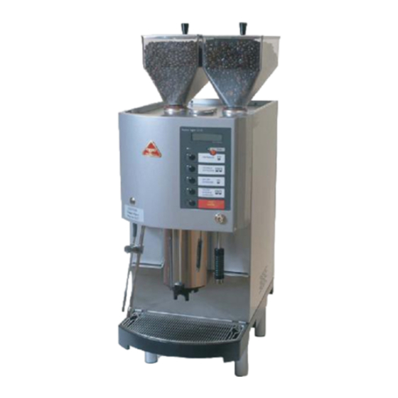
- Page 7 EGRO 55 SERIES TECHNICAL MANUAL 1.1a MACHINE OVERVIEW: MODEL 5511 MODEL 5511 ITEM Bean Hoppers (capacity 2.8 lbs of coffee beans) Display screen Key pad Programming key Hot water spout Grounds drawer door + access to main power & water switches...
- Page 8 EGRO 55 SERIES TECHNICAL MANUAL 1.1b. MACHINE OVERVIEW: MODEL 5513 CLOSE-UP OF MACHINE PARTS CLOSE-UP OF FRIDGE PARTS MODEL 5513 ITEM Model 5513 includes items 1-14 as described on the previous page PLUS the following items... Above the counter Model KS refrigerator...
- Page 9 30amp main power supply. If you are located in a area which experiences fl uctuations in power which cause the main power supply to drop below 208V, it is highly recommended that you install a power booster in line with the Egro 55 series equipment. Electrical adaptors, multiple sockets, and or extensions should not be used.
- Page 10 3 GPG or the warranty of the machine may be voided. PLEASE NOTE: A water fi ltration and softening system can be purchased through Rancilio or a high quality espresso equipment fi ltration system may be used, however all pre-installed systems are subject to inspection and approval by a certifi...
- Page 11 4 GPG or the warranty of the machine may be voided. PLEASE NOTE: A water fi ltration and softening system can be purchased through Rancilio or a high quality espresso equipment fi ltration system may be used, however all pre-installed systems are subject to inspection and approval by a certifi...
-
Page 12: Table Of Contents
EGRO 55 SERIES TECHNICAL MANUAL SECTION 2: INSTALLATION TABLE OF CONTENTS: SECTION 2 Page 2.1 INSTALLATION OVERVIEW......................2 2.2 - 2.12 STEP BY STEP INSTRUCTIONS FOR INSTALLATION .............. 3 - 12 2.2 Install feet on machine and KS fridge (for model 5513)................3 2.3 Install bean hoppers.......................... - Page 13 This page is intentionally left blank.
-
Page 14: Installation Overview
- (4) 5” Feet - (1) Service card - Cleaning tablets - (1 jar) TOOLS NEEDED The following tools are need for installing the Egro 55 series: - Phillips screwdriver (P1 x 3) - Standard 3/16 screw driver - Small crescent wrench... -
Page 15: Install Feet On Machine And Ks Fridge (For Model 5513)
(WITH MODEL 5513) The Egro 55 Series machine comes with riser feet to provide adequate space to easily clean beneath the machine. The Egro Model 5511 comes with 4 fee, and the 5513 with a KS Fridge comes with 8 feet, four for the machine and four for the fridge. -
Page 16: Connect Water To Machine
3 Grains Per Gallon or less. 1. Flush the water softener/fi lter with approximately 3 gallons of fresh water. 2. Connect the softener/fi lter system to the Egro 55 series machine. This section is intentionally left blank. - Page 17 EGRO 55 SERIES TECHNICAL MANUAL 2.2 - 2.12 INSTALLATION INSTRUCTIONS: STEP BY STEP GUIDE 2.5A CONNECT THE DRAIN LINE TO THE HOUSE DRAIN (MODEL 5511) right side panel screws STEPS TO CONNECT THE EGRO MODEL 5511 ATTACHING THE SILICON HOSE 1.
- Page 18 EGRO 55 SERIES TECHNICAL MANUAL 2.2 - 2.12 INSTALLATION INSTRUCTIONS: STEP BY STEP GUIDE 2.5B CONNECT THE DRAIN LINE TO THE HOUSE DRAIN ON THE MODEL 5513 FOLLOW STEPS 1 - 9 AS DESCRIBED FOR INSTALLING THE DRAIN HOSE OF A MODEL 5511. PLUS FOLLOWING THESE STEPS...
- Page 19 EGRO 55 SERIES TECHNICAL MANUAL 2.2 - 2.12 INSTALLATION INSTRUCTIONS: STEP BY STEP GUIDE 2.6 CONNECT THE KS FRIDGE TO THE MACHINE (MODEL 5513 ONLY) - CONTINUED CONNECT MILK RINSING LINE 7. Locate the milk rinsing line in the fridge. This is the clear shorter tefl on hose. Route it through the hole on the right side panel of the fridge and through the hole on the left side panel of the machine.
-
Page 20: Turn Machine On
2.8 CONNECT THE MACHINE TO POWER SUPPLY PLEASE NOTE: The Egro 55 series machine requires a NEMA L6-30R receptacle. The optimal voltage supply is 230V. An acceptable range of voltage is 208V - 250V. If the power supply does not produce 208V of steady voltage, a voltage booster is required. If the power is above 250V, a buck’n boost transformer may be required. -
Page 21: Depressurize Steam Boiler
1. After turning on the machine press the Latte button until steam does not escape any longer. WARNING: do not try and to program the Egro 55 series machine, while it’s depressurizing. TIP: If Error 93 appears on the display screen, turn the machine off - wait 10 seconds and then turn it back on. -
Page 22: Calibrate Machine To Beans
This step is critical to the proper function of the Egro 55 series machines. It gives the machine an accurate starting point to produce all drinks. It is unique to the roast of espresso or coffee beans. If you change the roast of beans used in the machine you will need to adjust this calibration by repeating the steps outlined below. - Page 23 EGRO 55 SERIES TECHNICAL MANUAL 2.2 - 2.12 INSTALLATION INSTRUCTIONS: STEP BY STEP GUIDE 2.12 CALIBRATE MACHINE TO BEANS (DIALING IN 10 GRAMS) - CONTINUED Config1... Config2... Products... Service... Product Total Grinders... Left Grinder, grinding time in seconds to produce 10 grams of coffee.
- Page 24 EGRO 55 SERIES TECHNICAL MANUAL 2.2 - 2.12 INSTALLATION INSTRUCTIONS: STEP BY STEP GUIDE 2.12 CALIBRATE MACHINE TO BEANS (DIALING IN 10 GRAMS) - CONTINUED 8.3 If the weight is not 10 grams, then scroll back (using the number 3 button) until the screen reads, GL Sec/10Gr.
- Page 25 EGRO 55 SERIES TECHNICAL MANUAL SECTION 3: PROGRAMMING TABLE OF CONTENTS: SECTION 3 Page 3.1 INTRODUCTION TO PROGRAMMING.................... 2 - 6 3.1a Keypad defi nitions..........................2 - 3 3.1b Changing operating mode: how to enter programming mode..............4 3.1c Programming menu overview........................5 - 6 3.2 CUSTOMER MONITORING MODE - OPERATING MODE 3...............
- Page 26 This page is intentionally left blank.
-
Page 27: Introduction To Programming
EGRO 55 SERIES TECHNICAL MANUAL 3.1 INTRODUCTION TO PROGRAMMING: 3.1a. KEY PAD DEFINITIONS All programming of the Egro equipment is done from the keypad. The buttons are labeled with small gray numbers. These numbers represent the corresponding product number. PLEASE NOTE:... - Page 28 EGRO 55 SERIES TECHNICAL MANUAL 3.1a. KEY PAD DEFINITIONS Each product button on the key pad represents a type of product in the programming. For example, button number 1 contains all the settings for the single espresso. Buttons 0, 1, 3, 5, 7 and 9 (all the buttons on the left side of the key pad) also have functional programming abilities such as Enter, Esc, Scroll up, scroll back, scroll forward, increase by 1 and decrease by 1).
-
Page 29: Changing Operating Mode: How To Enter Programming Mode
Technical menu mode...: this mode is for advanced programming and diagnostic testing. Please do not access this mode unless you have been properly certifi ed, by Rancilio through either a Train the Trainer Course or a Service Technician Course. Mode: 5:... -
Page 30: Programming Menu Overview
3.1c. PROGRAMMING MENU OVERVIEW DIAGRAM Products... Config1... Product Total CONTINUED ON NEXT PAGE P_Price P_Name Grinders... NBUP P_Type P_Reg. Nr. GL Sec/10Gr PT Clear? B-Emptying P_Bypass P_FM Pulses GR Sec/10Gr P_Gram Grinder L test? P_Cap Time Grinder R test? P_Foam Ref-Temp. - Page 31 3.1c. PROGRAMMING MENU OVERVIEW -- CONTINUED Config2... Service... Last Errors Language PT-Eraser Error Decimal Point Auto-Steam Cycles Periph. Type iButton Foam P-Serv Card System iButton Milk Max cycles M_Value iSteamCorrFct CLR P-Serv Steam Boiler Ref. Temp. AS W-Serv Power Fahrenheit Watertank Max.
-
Page 32: Customer Monitoring Mode - Operating Mode 3
EGRO 55 SERIES TECHNICAL MANUAL 3.2 CUSTOMER MONITORING MODE -- OPERATING MODE 3 The Product total menu allows customers to easily monitor the total number of products that have been produced using the Egro 55 series machine. 1. Change the operating mode of the machine to, MODE 3 (Customer Monitoring mode or Product Total menu) Insert key turn to the right. - Page 33 EGRO 55 SERIES TECHNICAL MANUAL 3.3 PRODUCT MENU: HOW TO SET DRINK PARAMETERS IN PROGRAMMING MODE The Products menu allows for the custom programming of each drink product individually. Every setting that can have an infl uence on the taste, quality and consistency of the drink may be fi ne-tuned using the Products menu.
- Page 34 EGRO 55 SERIES TECHNICAL MANUAL 3.3 PRODUCT MENU: HOW TO SET DRINK PARAMETERS IN PROGRAMMING MODE DESCRIPTION OF PRODUCT SETTINGS/PARAMETERS: --- CONTINUED PROGRAMING MENU DIAGRAM Products... Config1... Config2... Service... Product Total USED FOR This setting determines the quantity of steamed milk that is delivered to produce...
- Page 35 EGRO 55 SERIES TECHNICAL MANUAL 3.3 PRODUCT MENU: HOW TO SET DRINK PARAMETERS IN PROGRAMMING MODE PROGRAMING MENU DIAGRAM Products... Config2... Config1... Service... Product Total NOT RECOMMENDED, MAY CAUSE ERRORS. P_Time Brewing time control or auto-adjust tamping control, modifi es the tamping pressure if the brewing time does not correspond to this set value.
- Page 36 EGRO 55 SERIES TECHNICAL MANUAL 3.3 PRODUCT MENU: PRODUCT NAME LIST Following is list of settings that correspond to the product name that will be displayed on the machine’s display screen when the user presses the product button. Products... NUMBER...
-
Page 37: Config 1 Menu
EGRO 55 SERIES TECHNICAL MANUAL 3.4 CONFIG 1 MENU Confi g 1 Menu contains parameters for making adjustments to the machine that do not effect the specifi c drink parameters. Config1... Config2... Products... Service... Product Total Grinders... Left Grinder, grinding time in seconds to produce 10 grams of coffee. - Page 38 EGRO 55 SERIES TECHNICAL MANUAL 3.4 CONFIG 1 MENU Confi g 1 Menu contains parameters for making adjustments to the machine that do not effect the specifi c drink parameters. Config1... Config2... Products... Service... Product Total Specifi es the total number of drinks that can be queued or preselected in modes 1 and 2.
-
Page 39: Config 2 Menu
EGRO 55 SERIES TECHNICAL MANUAL 3.5 CONFIG 2 MENU Confi g 2 Menu contains parameters for making adjustments to the machine that do not effect the specifi c drink parameters. Config2... Products... Config1... Service... Product Total Specifi es which language. - Page 40 EGRO 55 SERIES TECHNICAL MANUAL 3.5 CONFIG 2 MENU Confi g 2 Menu contains parameters for making adjustments to the machine that do not effect the specifi c drink parameters. Config2... Products... Config1... Service... Product Total Uploads the settings from a service card to the Products, Confi g1, and Confi g2 menus of the machine.
- Page 41 EGRO 55 SERIES TECHNICAL MANUAL 3.5 CONFIG 2 MENU Confi g 2 Menu contains parameters for making adjustments to the machine that do not effect the specifi c drink parameters. Config2... Products... Config1... Service... Product Total Cleaning request function. Use this feature to set a cleaning alert after a specifi ed number of drinks have been produced.
- Page 42 EGRO 55 SERIES TECHNICAL MANUAL 3.5 CONFIG 2 MENU Confi g 2 Menu contains parameters for making adjustments to the machine that do not effect the specifi c drink parameters. Config2... Products... Config1... Service... Product Total ISTEAM SETTINGS: ONLY VALID WHEN ISTEAM WAND IS PRESENT...
-
Page 43: Service Menu
EGRO 55 SERIES TECHNICAL MANUAL 3.6 SERVICE MENU Service menu is for maintenance and diagnostics. It contains information as well as component diagnostic tests. Service... Products... Config1... Config2... Product Total Submenu which contains last errors machine encountered. Last Errors E061... - Page 44 EGRO 55 SERIES TECHNICAL MANUAL 3.6 SERVICE MENU Service menu is for maintenance and diagnostics. It contains information as well as component diagnostic tests. Service... Products... Config1... Config2... Product Total Displays the number of milk cleanings since the last CLR P-Serv.
- Page 45 EGRO 55 SERIES TECHNICAL MANUAL 3.6 SERVICE MENU Service... Products... Config1... Config2... Product Total Contains a list of submenu tests that can be used to diagnose a problem. Monitor... Function: Manually control the AC motor. AC Motor Test.. Buttons used to select: + and -...
- Page 46 EGRO 55 SERIES TECHNICAL MANUAL 3.6 SERVICE MENU Service... Products... Config1... Config2... Product Total Contains a list of submenu tests that can be used to diagnose a problem. Monitor... Flow meter P1 (coffee) FlowM Test Function: Check the fl ow-meter.
-
Page 47: Guide To Led On Main Board
EGRO 55 SERIES TECHNICAL MANUAL 3.7 GUIDE TO LED ON MAIN BOARD 3.7a LED LIST FOR R1 MAINBOARD LED 1 24 Volt (green continuous) LED 2 5 Volt (green continuous) LED 3 Run mode (green fl ashing) LED 4 Pump... -
Page 48: Error List
EGRO 55 SERIES TECHNICAL MANUAL 3.8 ERROR LIST 3.8 ERROR MESSAGES: When the machine has encounters a problem with one of it’s components it will give the end user an error message. Technicians can check the list of errors the machine has encountered and the number of cycles the machine had performed when the error occurred. - Page 49 EGRO 55 SERIES TECHNICAL MANUAL 3.8 ERROR LIST - CONTINUED 3.8 ERROR MESSAGES -continued DESCRIPTION SOLUTION Lower piston (P2) can not reach it’s a. Check lower spindle motor (M8) - use monitor menu maximum height. b. Revolution counter (S16) is faulty Lower piston (P2) height has a.
-
Page 50: Parameter Quick Index
EGRO 55 SERIES TECHNICAL MANUAL 3.9 PARAMETER QUICK INDEX PRODUCT SETTINGS PRODUCT SETTINGS: COFFEE PARAMETER DESCRIPTION MENU PAGE P_Bypass % of H 2 O delivered after brewing for Americanos Products... P_Coffee Source Specifi es which hopper supplies coffee Products... P_FM Pulse Quantity of water delivered during brewing Products... - Page 51 EGRO 55 SERIES TECHNICAL MANUAL 3.9 PARAMETER QUICK INDEX MACHINE SETTINGS MACHINE SETTINGS: GRINDER CALIBRATION PARAMETER DESCRIPTION MENU PAGE Grind Time Left -- GL Sec/10Gr Defi nes grind time to grind 10 grams with left grinder Confi g 1... Right -- GR Sec/10Gr Defi...
- Page 52 EGRO 55 SERIES TECHNICAL MANUAL 3.9 PARAMETER QUICK INDEX SENSORS, ALERTS, AND COUNTERS PARAMETER DESCRIPTION MENU PAGE C-Cleaning Displays number of times the coffee cleaning program has been run since last Service... CLR-R-Serv CLR_Error Clears error history Service... CLR_P_Serv Clears PM service counter Service...
- Page 53 EGRO 55 SERIES TECHNICAL MANUAL 3.9 PARAMETER QUICK INDEX TECHNICIAN SUPPORT MENUS COMPONENT MONITORING PARAMETER DESCRIPTION MENU PAGE AC Motors Manually control the AC motors. Service/Monitor... Additional IO Checks the 24V DC outputs. Service/Monitor... Cool Down Cool down the machine for safe repairing. Flushes the boiler with cold water.
-
Page 54: Alphabetical List Of Parameters Index
EGRO 55 SERIES TECHNICAL MANUAL 3.10 ALPHABETICAL LIST OF PARAMETERS INDEX PARAMETER MENU PAGE PARAMETER MENU PAGE PARAMETER MENU PAGE Power version Confi g 2 AC Motors Service/Monitor M_Cleanings Service Pre-Rinse Confi g 1 Additional IO Service/Monitor Max_Cycles Service Pre-sel Mode 1 Confi... - Page 55 EGRO 55 SERIES TECHNICAL MANUAL SECTION 4: ELECTRICAL TABLE OF CONTENTS: SECTION 4 Page 4.1 INTRODUCTION..........................2 4.2 HIGH VOLTAGE COMPONENTS....................2 - 4 4.3 LOW VOLTAGE COMPONENTS..................... 5 - 7 4.4 MAINBOARD DIAGRAM....................... 8 - 9 4.5 MAINBOARD SCHEMATICS ....................... 10 - 11 E55_TM_S4_electricalV3 ©...
- Page 56 This page is intentionally left blank.
- Page 57 EGRO 55 SERIES TECHNICAL MANUAL 4.1 INTRODUCTION The electrical section of this manual details the electrical components of the Egro 55 series machines. The electrical components are broken out into three main sections, 1. High voltage 2. Low voltage 3.
- Page 58 EGRO 55 SERIES TECHNICAL MANUAL EGRO 55 SERIES TECHNICAL MANUAL 4.2 HIGH VOLTAGE COMPONENTS - CONTINUED OPERATING MODES HEATING ELEMENT: HEATING ELEMENT: HOT WATER BOILER STEAM BOILER The hot water boiler or coffee boiler The steam boiler contains a 208V contains a 208V 3000w external 3000w internal heating element.
- Page 59 EGRO 55 SERIES TECHNICAL MANUAL EGRO 55 SERIES TECHNICAL MANUAL 4.2 HIGH VOLTAGE COMPONENTS - CONTINUED POWER SWITCH CAPACITORS Turns the machine on and off. 230v 230v incoming. HIGH LIMIT SWITCH: HIGH LIMIT SWITCH: HOT WATER BOILER STEAM BOILER The hot water boiler high limit has a The steam boiler high limit cuts both switch for each leg of power.
- Page 60 EGRO 55 SERIES TECHNICAL MANUAL EGRO 55 SERIES TECHNICAL MANUAL 4.3 LOW VOLTAGE COMPONENTS FLOWMETER BREW CHAMBER HEAT SLEEVE 24v + 5v. Counts the pulses of the 24v. Keeps the brew chamber at water going to the hot water boiler constant temperature, to promote and the brew group.
- Page 61 EGRO 55 SERIES TECHNICAL MANUAL EGRO 55 SERIES TECHNICAL MANUAL 4.3 LOW VOLTAGE COMPONENTS - CONTINUED PISTON MOTORS TS OR iSTEAM WAND PROBE 24v. Contains two (upper and lower) 5v. Temperature sensing probe for piston motors, that power the upper steaming milk.
- Page 62 EGRO 55 SERIES TECHNICAL MANUAL EGRO 55 SERIES TECHNICAL MANUAL 4.3 LOW VOLTAGE COMPONENTS - CONTINUED SOLENOIDS: MODEL 5513 In addition, to the fi ve solenoids located in the Model 5511, there are three solenoids exclusive to the Model 5513.
- Page 63 EGRO 55 SERIES TECHNICAL MANUAL EGRO 55 SERIES TECHNICAL MANUAL 4.4 MAINBOARD DIAGRAM Diagram for the R2 Mainboard on the Egro 55 Series - Section 4: Page 8 - © Copyright 2008. Rancilio North America E55_TM_S4_electricalV3...
- Page 64 EGRO 55 SERIES TECHNICAL MANUAL EGRO 55 SERIES TECHNICAL MANUAL 4.4 MAINBOARD DIAGRAM - CONTINUED LED LIST FOR R2 MAINBOARD INPUT LIST DL 1 24 Volt (green continuous) orange, green, 2x grey = leads to power board 2x white = lead to 6.3a fuse...
- Page 65 EGRO 55 SERIES TECHNICAL MANUAL SECTION 5: HYDRAULIC TABLE OF CONTENTS: SECTION 5 Page 5.1 INTRODUCTION..........................2 5.2 HOT WATER (COFFEE) BOILER......................2 - 3 5.3 STEAM BOILER..........................3 - 5 5.4 BREW GROUP ASSEMBLY......................6 - 7 E55_TM_S5_HyraulicV3 © Copyright 2008. Rancilio North America...
- Page 66 This page is intentionally left blank.
-
Page 67: Introduction
EGRO 55 SERIES TECHNICAL MANUAL 5.1 INTRODUCTION The hydraulic and steam section of this manual details the hydraulic components of the Egro 55 series. The hydraulic components are broken down into three main sections, 1. Hot Water or Coffee Boiler 2. -
Page 68: Steam Boiler
EGRO 55 SERIES TECHNICAL MANUAL 5.2 HOT WATER (COFFEE) BOILER OPERATING MODES INCOMING WATER CHECK WATER PRESSURE GAUGE VALVE Located on the bottom of the boiler. Located on the bottom of the boiler. Indicates the water pressure from the Allows water to only pass in one pump through the boiler. - Page 69 EGRO 55 SERIES TECHNICAL MANUAL 5.3 STEAM BOILER - CONTINUED PRESSURE STAT STEAM SOLENOID - HOT WATER Regulates the pressure of the steam boiler. Adjustable from the top. Supplies steam to the mixing chamber for use with hot water. TS STEAM WAND SOLENOID...
- Page 70 EGRO 55 SERIES TECHNICAL MANUAL 5.3 STEAM BOILER - CONTINUED WATER LEVEL PROBE INJECTION CHAMBER Regulates the water level in the steam Union where steam meets water from boiler. coffee boiler and continues on to hot Red wire -- sends date to Mainboard water tap.
-
Page 71: Brew Group Assembly
EGRO 55 SERIES TECHNICAL MANUAL 5.4 BREW GROUP ASSEMBLY Following is a diagram of the brew group assembly. All brewing and extraction takes place in the brew group assembly. For a complete guide to repairing and rebuilding the brew group, please see section 6 of this manual. - Page 72 EGRO 55 SERIES TECHNICAL MANUAL 5.4 BREW GROUP ASSEMBLY - CONTINUED BREW GROUP ASSEMBLY DIAGRAM KEY Upper piston quick- connect fi tting. Connects incoming water from the hot water (coffee) boiler to the brew chamber. Bottom piston quick-connect fi tting. Delivers extracted espresso to the coffee outlet.
- Page 73 EGRO 55 SERIES TECHNICAL MANUAL SECTION 6: ADJUSTMENTS AND MAINTENANCE TABLE OF CONTENTS: SECTION 5 Page Adjustments 6.1 CALIBRATING MACHINE TO BEANS - DIALING IN 10 GRAMS............2 - 3 6.2 ADJUSTING GRIND......................... 3 Maintenance 6.3 REPLACING BREW GROUP......................6 6.4 DRAINING THE STEAM BOILER......................
- Page 74 This page is intentionally left blank.
-
Page 75: Calibrating Machine To Beans - Dialing In 10 Grams
This step is critical to the proper function of the Egro 55 series machines. It gives the machine an accurate starting point to produce all drinks. It is unique to the roast of espresso or coffee beans. If you change the roast of beans used in the machine you will need to adjust this calibration by repeating the steps outline below. - Page 76 EGRO 55 SERIES TECHNICAL MANUAL 6.1 CALIBRATING MACHINE TO BEANS - DIALING IN 10 GRAMS - CONTINUED OPERATING MODES 4. You have accessed the Grinders submenu. There are four options in the grinder menu, they are described in the diagram above.
-
Page 77: Adjusting Grind
EGRO 55 SERIES TECHNICAL MANUAL 6.2 ADJUSTING THE GRIND This is the fi rst step in calibrating the machine to the roast of bean which is being served. This will need to be done using the beans that will be served. -
Page 78: Replacing Brew Group
EGRO 55 SERIES TECHNICAL MANUAL 6.3 REPLACING BREW GROUP ASSEMBLY REMOVE AND REPLACE THE BREW GROUP ASSEMBLY (BGA) 1 Turn off and unplug the machine 2 Remove the left and right side panels of machine 3 Disconnect the piston motors and brew chamber heating element power cables from the motherboard -->... -
Page 79: Replacing Grinder Burrs
EGRO 55 SERIES TECHNICAL MANUAL 6.5 REPLACING GRINDER BURRS Rancilio recommends changing the grinder burrs every burrs every 100,000 - 120,000 Cycles. This will help to increase the life of your grinder motors. STEPS TO REPLACING THE GRINDER BURRS 1. Turn off the machine and unplug it 2. - Page 80 EGRO 55 SERIES TECHNICAL MANUAL THIS PAGE IS INTENTIONALLY LEFT BLANK. - Section 6: Page 7 - © Copyright 2008. Rancilio North America E55_TM_S6_Adjustment_Maintenance V3...
-
Page 81: Pm Guide
This guide is intended for certifi ed factory trained technicians only. Should you have any questions or need further assistance, please contact Rancilio North America at: (877) 726-2454. Extension: 208 There are two different types of preventative maintenance visits recommended for the EGRO Series 55 LEASE machines. - Page 82 EGRO 55 SERIES TECHNICAL MANUAL 6.6 PM GUIDE DESCRIPTION OF PARTS: PISTON ASSEMBLY, UPA OR LPA: The upper and lower piston assemblies are identical except for the actual pistons. BREW GROUP ASSEMBLY OR BGA: the complete brewing module of the Egro 55 series espresso machines.
- Page 83 EGRO 55 SERIES TECHNICAL MANUAL 6.6 PM GUIDE DESCRIPTION OF PARTS --- Continued LOWER PISTON 21. Piston Shaft 22. Quick connect for hose 23. Piston head 24. Lower piston O-ring 25. Shower screen LOWER PISTON: This is an exploded view of the lower piston.
- Page 84 EGRO 55 SERIES TECHNICAL MANUAL 6.6 PM GUIDE STEPS FOR PM TYPE 1: EXCHANGING THE BGA USING A NEW OR REBUILT BREW GROUP ASSEMBLY (BGA) EMPTY STEAM BOILER AND TURN OFF MACHINE 1.1 Turn key to right and press the number 5 button display should read M_5: Heater Off.
- Page 85 EGRO 55 SERIES TECHNICAL MANUAL 6.6 PM GUIDE STEPS FOR PM TYPE 1: EXCHANGING THE BGA USING A NEW OR REBUILT BREW GROUP ASSEMBLY (BGA) TEST WATER HARDNESS 5.1 Test water hardness and record GPG on PM Checklist/sign-off sheet. REPLACE WATER FILTRATION AND SOFTENING CARTRIDGES 6.1 Replace in line water fi...
- Page 86 EGRO 55 SERIES TECHNICAL MANUAL 6.6 PM GUIDE ALTERNATIVE STEPS FOR PM TYPE 1: ON-SITE O-RING EXCHANGE A-1. REMOVE BGA FROM MACHINE AND REMOVE GROUNDS PUCK CHUTES A1.1 Remove the BGA from the machine: Follow steps 1.1 to 1.7 as described in STEP 1.
- Page 87 EGRO 55 SERIES TECHNICAL MANUAL 6.6 PM GUIDE ALTERNATIVE STEPS FOR PM TYPE 1: ON-SITE O-RING EXCHANGE A-3. REMOVE UPPER PISTON O-RINGS A3.1 Place the BGA on the workbench and remove the Upper Piston Assembly (UPA) by loosening the two cotter pins, and gently pulling the sides of the BGA housing apart and pulling upward on the UPA.
- Page 88 EGRO 55 SERIES TECHNICAL MANUAL 6.6 PM GUIDE ALTERNATIVE STEPS FOR PM TYPE 1: ON-SITE O-RING EXCHANGE A-4. REPLACE AND LUBRICATE UPPER PISTON O-RINGS A4.1 Lubricate upper piston groove LUBE: Viper Lube Loctite PN 36781 A4.2 Replace the upper piston scrapper ring and O-ring PN: 039061 and 0390654 A4.3 Reassemble the shower screen and stainless steel upper piston plate onto upper piston...
- Page 89 EGRO 55 SERIES TECHNICAL MANUAL 6.6 PM GUIDE ALTERNATIVE STEPS FOR PM TYPE 1: ON-SITE O-RING EXCHANGE A-5. REASSEMBLE UPPER PISTON A5.1 Reassemble piston onto the UPA by turning it down the auger shaft using a 3mm Allen wrench inserted into the...
- Page 90 EGRO 55 SERIES TECHNICAL MANUAL 6.6 PM GUIDE ALTERNATIVE STEPS FOR PM TYPE 1: ON-SITE O-RING EXCHANGE A-6. REMOVE LOWER PISTON O-RINGS -- C ONTINUED A6.4 Remove the shower screen by unscrewing the screw on the end of the piston.
- Page 91 EGRO 55 SERIES TECHNICAL MANUAL 6.6 PM GUIDE ALTERNATIVE STEPS FOR PM TYPE 1: ON-SITE O-RING EXCHANGE A-8. REASSEMBLE UPA AND LPA INTO BREW GROUP ASSEMBLY A8.1 Mount lower piston assembly into brew unit housing TOOL: 3mm Allen wrench PLEASE NOTE: the motor goes to the left (when the BGA is facing towards you) and the cotter pins are inserted from the front of the BGA A8.2 Mount the upper piston assembly into the brew unit housing...
- Page 92 EGRO 55 SERIES TECHNICAL MANUAL 6.6 PM GUIDE ALTERNATIVE STEPS FOR PM TYPE 1: ON-SITE O-RING EXCHANGE A-10. REATTACH GROUNDS SLIDES TO SIDES OF BGA A9.1 Reattach the grounds slides to the sides of the BGA TIP: The shorter bent puck slide goes on the right side of the BGA, when the BGA is facing towards you (Funnel towards you) A10.1...
- Page 93 EGRO 55 SERIES TECHNICAL MANUAL 6.6 PM GUIDE STEPS FOR PM TYPE 2 PERFORM ALL THE STEPS NECESSARY FOR PM TYPE 1 PLUS FOLLOWING STEPS! PLEASE NOTE: If you do not have a new or rebuilt BGA, and are following the alternative steps for on-site O-ring exchange, please also exchange the brew shower screens instead of cleaning them.
- Page 94 EGRO 55 SERIES TECHNICAL MANUAL 6.6 PM GUIDE STEPS FOR PM TYPE 2 14: REPLACE THE SEAL ON THE STEAM WAND TIP 14.1 Replace the seal on the steam wand tip --> PN: 040501 threads of the PLEASE NOTE: Be careful not to slice the seal when reassembling the tip to the wand, the steam tip are very sharp.
- Page 95 6.6 PM GUIDE: CHECKLIST AND SIGN-OFF SHEET This form is to be completed by the service technician performing the Preventative Maintenance visit. CUSTOMER INFORMATION SERVICE TECH INFORMATION ’ OMPANY ECHNICIAN OCATION TATE OMPANY HONE UMBER OTAL YCLES ERFORMED MAIL 2 (please circle) PM V LEANING YCLES...
- Page 96 EGRO 55 SERIES TECHNICAL MANUAL This page was intentionally left blank. - Section 6: Page 23 - © Copyright 2008. Rancilio North America E55_TM_S6_Adjustment_Maintenance V3...
-
Page 97: Brew Group Rebuild Guide
This guide is intended for certifi ed factory trained technicians only. It is recommended that you bring BGA’s back to your shop to rebuild them. Should you have any questions or need further assistance, please contact Rancilio North America at: (877) 726-2454. - Page 98 EGRO 55 SERIES TECHNICAL MANUAL 6.7 BREW GROUP REBUILD GUIDE DESCRIPTION OF PARTS: Piston Assembly, UPA or LPA: The upper and lower piston assemblies are identical except for the actual pistons. Brew Group Assembly or BGA: the complete brewing module of the Egro 55 series espresso machines.
- Page 99 EGRO 55 SERIES TECHNICAL MANUAL 6.7 BREW GROUP REBUILD GUIDE DESCRIPTION OF PARTS --- Continued Lower Piston: This is an exploded view of the lower piston Upper Piston: This is an exploded view of the upper piston. Upper Piston 12. Brass pins to hold piston guide arms (13) 13.
- Page 100 EGRO 55 SERIES TECHNICAL MANUAL 6.7 BREW GROUP REBUILD GUIDE 1. REMOVE BGA FROM THE MACHINE 1.1 Unplug the machine 1.2 Remove the left and right side panels of machine 1.3 Disconnect the piston motor and brew chamber heating element power cables from the motherboard PLEASE NOTE: These are the connections J2, J3 and J16 on the motherboard 1.4 Discount the coffee and water deliver hoses from the brew valve on the coffee boiler and the espresso outlet on the...
- Page 101 EGRO 55 SERIES TECHNICAL MANUAL 6.7 BREW GROUP REBUILD GUIDE 3. REMOVE HOSES FROM PISTONS 3.1 Remove hoses from both the upper and lower pistons - Section 6: Page 28 -...
- Page 102 EGRO 55 SERIES TECHNICAL MANUAL 6.7 BREW GROUP REBUILD GUIDE 4. DISASSEMBLE AND CLEAN THE UPPER PISTON ASSEMBLY (UPA) 4.1 Place the BGA your work area and remove the Upper Piston Assembly (UPA) by loosening the two cotter pins, and gently pulling the sides of the BGA housing apart and pulling upward on the UPA.
- Page 103 EGRO 55 SERIES TECHNICAL MANUAL 6.7 BREW GROUP REBUILD GUIDE 4. DISASSEMBLE AND CLEAN THE UPA --- Continued 4.7 Remove the upper piston scrapper ring and the orange O-ring from the piston head 4.8 Wipe all upper piston components clean with water solution and towel 4.9 Wipe entire upper assembly clean with a damp towel...
- Page 104 EGRO 55 SERIES TECHNICAL MANUAL 6.7 BREW GROUP REBUILD GUIDE 5. REASSEMBLE THE UPPER PISTON ASSEMBLY (UPA) 5.1 Lubricate upper piston groove LUBE: Viper lube Loctite PN 36781 5.2 Replace the upper piston scrapper ring and O-ring PN: ?????? and 039064 5.3 Reassemble the shower screen and stainless steel upper piston plate onto upper piston...
- Page 105 EGRO 55 SERIES TECHNICAL MANUAL 6.7 BREW GROUP REBUILD GUIDE 5. REASSEMBLE THE UPA --- Continued 5.10 5.8 Lubricate upper piston auger and auger hole in the piston shaft LUBE: Krytox RFE PFPE Lube, Loctite PN 29711 (green tube) 5.9 Reassemble piston onto the UPA by turning it down the auger shaft using a 3mm Allen wrench inserted into the gear...
- Page 106 EGRO 55 SERIES TECHNICAL MANUAL 6.7 BREW GROUP REBUILD GUIDE 6. DISASSEMBLE AND CLEAN THE LOWER PISTON ASSEMBLY (LPA) 6.1 Place the BGA on the counter (upside down) and remove the Lower Piston Assembly (LPA) by loosening the two cotter pins, and gently pulling the sides of the BGA housing apart and pulling upward on the LPA. If necessary, place pins in water to remove coffee build-up.
- Page 107 EGRO 55 SERIES TECHNICAL MANUAL 6.7 BREW GROUP REBUILD GUIDE 6. DISASSEMBLE AND CLEAN THE LPA --- Continued 6.8 Remove wiring harnesses from mounting plate below motor and piston sensing arm by unscrewing screws using a Phillip’s head screwdriver TOOL: Phillip’s head screwdriver 6.10...
- Page 108 EGRO 55 SERIES TECHNICAL MANUAL 6. DISASSEMBLE AND CLEAN THE LPA --- Continued 6.13 6.12 Remove all components from water solution and wipe dry and clean using towel and toothbrush if necessary. 6.13 Clean all lube from auger shaft using a piece of plastic wrap or a towel.
- Page 109 EGRO 55 SERIES TECHNICAL MANUAL 7. REASSEMBLE THE LOWER PISTON ASSEMBLY (LPA) 7.1 Lubricate lower piston groove LUBE: Viper lube Loctite PN 36781 7.2 Replace lower piston O-ring PN: 029441 (small orange seal) 7.3 Reassemble brew screen onto lower piston TOOL: Screwdriver 7.4 Reattach piston shaft to piston head using Allen screws...
- Page 110 EGRO 55 SERIES TECHNICAL MANUAL 6.7 BREW GROUP REBUILD GUIDE 7. REASSEMBLE THE LPA --- Continued 7.8 Reattach motor wire harnesses to LPA TIP: Green, yellow, pink wires attach to the motor sensor arm (UP) Gray, brown and white wires attach to the LPA base (DOWN)
- Page 111 EGRO 55 SERIES TECHNICAL MANUAL 6.7 BREW GROUP REBUILD GUIDE 8. DISASSEMBLE THE BREW GROUP HOUSING/FRAME (If necessary) PLEASE NOTE: If there is excess coffee build-up please disassemble the brew group housing and clean it thoroughly. 8.1 Disassemble brew chamber housing by unscrewing the cotter pins TOOL: 3mm Allen wrench 8.2 Thoroughly clean brew chamber and housing using wet cloth...
- Page 112 EGRO 55 SERIES TECHNICAL MANUAL 6.7 BREW GROUP REBUILD GUIDE 10. REASSEMBLE UPA and LPA INTO BREW GROUP ASSEMBLY 10.1 10.2 10.3 10.1 Mount lower piston assembly into brew unit housing. TOOL: 3mm Allen wrench PLEASE NOTE: the motor goes to the left (when the BGA is facing towards you) and the cotter pins are inserted from the front of the BGA.
- Page 113 EGRO 55 SERIES TECHNICAL MANUAL 6.7 BREW GROUP REBUILD GUIDE 11. REATTACH HOSES TO UPPER AND LOWER PISTONS 11.1 11.1 Reattach the hoses to the upper and lower pistons 12. REATTACH GROUNDS SLIDES TO SIDES OF BGA 12.1 12.1 Reattach the grounds slides to the sides of the BGA.
- Page 114 EGRO 55 SERIES TECHNICAL MANUAL 6.7 BREW GROUP REBUILD GUIDE C O N GRAT U LAT IO N S! CONG R AT U L AT I O N S! YO U H AVE REFU RB ISH ED YO U H AVE R E FU RB IS HED...
Need help?
Do you have a question about the EGRO 55 Series and is the answer not in the manual?
Questions and answers