Table of Contents
Advertisement
Quick Links
Advertisement
Table of Contents

Related Manuals for Advantech EKI-7712 Series


Summary of Contents for Advantech EKI-7712 Series
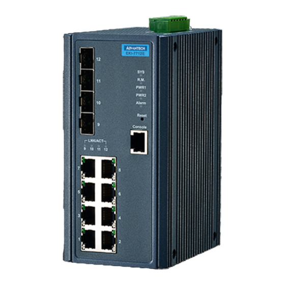
- Page 1 User Manual EKI-7712 Series 8FE+4G/8GE+4G SFP port L2 Managed Switch...
- Page 2 No part of this manual may be reproduced, copied, translated or transmitted in any form or by any means without the prior written permission of Advantech Co., Ltd. Information provided in this manual is intended to be accurate and reliable. How- ever, Advantech Co., Ltd.
- Page 3 Technical Support and Assistance Visit the Advantech web site at www.advantech.com/support where you can find the latest information about the product. Contact your distributor, sales representative, or Advantech's customer service center for technical support if you need additional assistance.
- Page 4 Before setting up the system, check that the items listed below are included and in good condition. If any item does not accord with the table, please contact your dealer immediately. 1 x Industrial Ethernet Switch 2 x Wall-mounting Bracket 1 x DIN-Rail mounting Bracket and Screws EKI-7712 Series User Manual...
- Page 5 The sound pressure level at the operator's position according to IEC 704-1:1982 is no more than 70 dB (A). DISCLAIMER: This set of instructions is given according to IEC 704-1. Advantech disclaims all responsibility for the accuracy of any statements contained herein.
- Page 6 Der arbeitsplatzbezogene Schalldruckpegel nach DIN 45 635 Teil 1000 beträgt 70dB(A) oder weiger. Haftungsausschluss: Die Bedienungsanleitungen wurden entsprechend der IEC- 704-1 erstellt. Advantech lehnt jegliche Verantwortung für die Richtigkeit der in die- sem Zusammenhang getätigten Aussagen ab. EKI-7712 Series User Manual...
- Page 7 Always disconnect the power from the device before servicing it. Before plugging a cable into any port, discharge the voltage stored on the cable by touching the electrical contacts to the ground surface. EKI-7712 Series User Manual...
-
Page 8: Table Of Contents
Accessing the CLI............... 30 Web Browser Configuration ..............30 3.3.1 Preparing for Web Configuration ..........31 3.3.2 System Login ................31 Chapter Managing Switch....... 32 Log In ...................... 33 Recommended Practices................ 33 4.2.1 Changing Default Password ............33 EKI-7712 Series User Manual viii... - Page 9 4.8.4 Bandwidth Guarantee ............... 113 Management ..................115 4.9.1 LLDP ..................115 4.9.2 SNMP..................119 4.9.3 Power Over Ethernet ..............122 4.9.4 TCP Modbus Settings ............... 124 4.9.5 DHCP Server ................125 4.9.6 SMTP Client................129 EKI-7712 Series User Manual...
- Page 10 4.11.5 Save Configuration ..............146 4.11.6 User Account ................146 4.11.7 N-Key..................147 4.11.8 Reset System ................147 4.11.9 Reboot Device ................147 4.12 Modbus/TCP Mapping ................148 4.12.1 Modbus/TCP Mapping Table ............ 148 Chapter Troubleshooting......160 Troubleshooting ..................161 EKI-7712 Series User Manual...
- Page 11 Serial Console Cable....................20 Figure 2.14 DB 9 Pin Position......................20 Figure 2.15 Pin Assignment......................20 Figure 2.16 Power Wiring for EKI-7712 Series................21 Figure 2.17 Grounding Connection....................23 Figure 2.18 Terminal Receptor: Relay Contact ................23 Figure 2.19 Terminal Receptor: Power Input Contacts..............24 Figure 2.20...
- Page 12 Figure 4.85 L2 Switching > Spanning Tree > STP Statistics............74 Figure 4.86 L2 Switching > X-Ring Elite > X-Ring Elite Settings............ 75 Figure 4.87 L2 Switching > X-Ring Elite > X-Ring Elite Groups ............. 75 EKI-7712 Series User Manual...
- Page 13 Security > DHCP Snooping > L2-Relay VLAN Settings ..........102 Figure 4.145 Security > DHCP Snooping > Circuit ID Settings ............102 Figure 4.146 Security > DHCP Snooping > L2 Relay Information..........102 Figure 4.147 Security > ARP Spoofing................... 103 xiii EKI-7712 Series User Manual...
- Page 14 Figure 4.204 Management > RMON > RMON History ..............132 Figure 4.205 Management > RMON > RMON Alarm..............133 Figure 4.206 Management > RMON > RMON Event ..............134 Figure 4.207 Management > NTP Server..................135 EKI-7712 Series User Manual...
- Page 15 Figure 4.222 Tools > User Account ....................146 Figure 4.223 Tools > User Account ....................146 Figure 4.224 Tools > User Account ....................147 Figure 4.225 Tools > N-Key......................147 Figure 4.226 Tools > N-Key Information..................147 EKI-7712 Series User Manual...
-
Page 16: Product Overview
Chapter Product Overview... -
Page 17: Supported Models
EKI-7712E-4F/EKI-7712E-4FI: 9.6 Gbps EKI-7712G-4FP/EKI-7712G-4FPI: 24 Gbps Power Power EKI-7712G-4F/EKI-7712G-4FI: 12.1 W@48Vdc Consumption (System) EKI-7712E-4F/EKI-7712E-4FI: 12.1 W@48Vdc (System) EKI-7712G-4FP/EKI-7712G-4FPI: 15 W@48Vdc (System) Power Input EKI-7712G-4F/EKI-7712G-4FI: 12V~48V EKI-7712E-4F/EKI-7712E-4FI: 12V~48V EKI-7712G-4FP/EKI-7712G-4FPI: 48V EKI-7712 Series User Manual... - Page 18 EN 61000-4-4 (EFT) Level 4 EN 61000-4-5 (Surge) Level 4 EN 61000-4-6 (CS) Level 4 EN 61000-4-8 (Magnetic Field) Level 4 Shock IEC 60068-2-27 Freefall IEC 60068-2-32 Vibration IEC 60068-2-6 Traffic Control NEMA TS2 EKI-7712 Series User Manual...
-
Page 19: Hardware Views
See “System LED Panel” on page 6 for further details. Reset button Button allows for system soft reset or factory default reset. Console serial port Console cable port to COM port (DB9 male) on computer to RS232 managed switch (RJ45 female). EKI-7712 Series User Manual... -
Page 20: Figure 1.2 Front View
See “System LED Panel (only for PoE model)” on page 7 for further details. Reset button Button allows for system soft reset or factory default reset. Console serial port Console cable port to COM port (DB9 male) on computer to RS232 managed switch (RJ45 female). EKI-7712 Series User Manual... -
Page 21: Figure 1.3 System Led Panel
Powered down or not installed PWR2 Solid green Powered up Power down or not installed Alarm Solid red Defined major policies are detected Blinking Red Defined minor policies are detected Powered off or system is operating normally EKI-7712 Series User Manual... - Page 22 Power down or not installed Alarm Solid red Defined major policies are detected Blinking Red Defined minor policies are detected Powered off or system is operating normally PoE (depending Solid green PoE activated. the PoE ports) PoE non-working. EKI-7712 Series User Manual...
-
Page 23: Rear View
Rear View Figure 1.5 Rear View Item Description Wall mounting holes Screw holes (x6) used in the installation of a wall mounting plate DIN-Rail mounting Mounting plate used for the installation to a standard DIN rail plate EKI-7712 Series User Manual... -
Page 24: Top View
The following view applies to EKI-7712G-4FP, EKI-7712G-4FPI, EKI-7712E-4FP and EKI-7712E-4FPI. V2+V2- V1+V1- DC48V 1A@24V PWR2 P-Fail PWR1 Figure 1.7 Top View Item Description Ground terminal Screw terminal used to ground chassis Terminal block Connect cabling for power and alarm wiring EKI-7712 Series User Manual... -
Page 25: Switch Installation
Chapter Switch Installation... -
Page 26: Installation Guidelines
The other LEDs turn off and return to their operating status. If the switch fails POST, the System LED switches to an amber state. After a successful self-test, power down the switch and disconnect the power cabling. The switch is now ready for installation on its final location. EKI-7712 Series User Manual... -
Page 27: Installing The Switch
DIN rail clip. If seated correctly, the bottom of the DIN rail should be fully inserted in the release tab. DIN rail clip DIN rail DIN rail clip release tab Figure 2.1 Installing the DIN-Rail Mounting Kit EKI-7712 Series User Manual... -
Page 28: Figure 2.2 Correctly Installed Din Rail Kit
Figure 2.2 Correctly Installed DIN Rail Kit Grasp the bottom of the switch and slightly rotate it upwards. If there is resis- tance, the switch is correctly installed. Otherwise, re-attempt the installation pro- cess from the beginning. EKI-7712 Series User Manual... -
Page 29: Wall-Mounting
Remove the DIN mounting plate. Store the DIN mounting plate and provided screws for later use. Align the wall mounting plates on the rear side. The screw holes on the device and the mounting plates must be aligned, see the following illustration. EKI-7712 Series User Manual... -
Page 30: Figure 2.4 Installing Wall Mount Plates
Do not completely tighten the screws into the wall. A final adjust- ment may be needed before fully securing the wall mounting plates on the wall. Align the wall mount plate over the screws on the wall. EKI-7712 Series User Manual... -
Page 31: Installing And Removing Sfp Modules
(A-to-A and B-to-B, as shown below, or A1-to-A2 and B1-to-B2). Note! This is a Class 1 Laser/LED product. To avoid causing serious damage to your eyes, do not stare directly into the Laser Beam. EKI-7712 Series User Manual... -
Page 32: Installing Sfp Modules
Remove the protective plug from the SFP transceiver. Note! Do not remove the dust plug from the transceiver if you are not installing the fiber optic cable at this time. The dust plug protects hardware from dust contamination. EKI-7712 Series User Manual... -
Page 33: Removing Sfp Modules
Hold the handle on the transceiver and pull the transceiver out of the slot. Handle Figure 2.11 Removing an SFP Transceiver Note! Replace the dust plug on the slot if you are not installing a transceiver. The dust plug protects hardware from dust contamination. EKI-7712 Series User Manual... -
Page 34: Connecting The Switch To Ethernet Ports
Pin 2 Pin 6 Pin 3 Pin 3 Pin 3 Pin 1 Pin 6 Pin 6 Pin 6 Pin 2 Figure 2.12 Ethernet Plug & Connector Pin Position Maximum cable length: 100 meters (328 ft.) for 10/100/1000BaseT. EKI-7712 Series User Manual... -
Page 35: Connecting The Switch To Console Port
Figure 2.13 Serial Console Cable Figure 2.14 DB 9 Pin Position DB9 Connector RJ45 Connector 1 Orange/White 2 Orange 3 Green/White 4 Blue 5 Blue/White 6 Green 7 Brown/White 8 Brown RJ45 Female Male Figure 2.15 Pin Assignment EKI-7712 Series User Manual... -
Page 36: Power Supply Installation
Single DC Power Redundant DC Power P2 P1 P2 P1 Chassis Chassis (pane) (pane) One DC Supply Dual DC Supplies Figure 2.16 Power Wiring for EKI-7712 Series EKI-7712 Series User Manual... -
Page 37: Considerations
Caution! Do not service equipment or cables during periods of lightning activity. Caution! Do not service any components unless qualified and authorized to do EKI-7712 Series User Manual... -
Page 38: Wiring A Relay Contact
2.7.4 Wiring a Relay Contact The following section details the wiring of the relay output. The terminal block on the EKI-7712 Series is wired and then installed onto the terminal receptor located on the EKI-7712 Series. V2+V2- V1+V1-... -
Page 39: Wiring The Power Inputs
Insert a small flat-bladed screwdriver in the V1+/V1- wire-clamp screws, and loosen the screws. Insert the negative/positive DC wires into the V+/V- terminals of PW1. If setting up power redundancy, connect PW2 in the same manner. EKI-7712 Series User Manual... -
Page 40: Reset Button
Reset configuration to factory default: Press and hold Reset button for 5 seconds. System reboot: Press and hold Reset button for 2 seconds. Note! Do NOT power off the Ethernet switch when loading default settings. EKI-7712 Series User Manual... -
Page 41: Configuration Utility
Chapter Configuration Utility... -
Page 42: First Time Setup
Secure Shell (SSH). An SNMP interface can be used to read/write many settings. Command Line Interface (CLI) can be used to read/write most settings. Initial setup must be done using an Ethernet connection (recommended) or the serial port. EKI-7712 Series User Manual... -
Page 43: Using The Graphical (Web) Interface
NTP Server: The IP address or domain name of an NTP (Network Time Proto- col) server from which the switch may retrieve the current time at startup. Please note that using a domain name requires that at least one domain name server be configured. EKI-7712 Series User Manual... -
Page 44: Configuring The Ethernet Ports
Otherwise, the switch will use the fixed Ethernet port and the correspond- ing settings for it. Note! When 100f is selected for the SFP of a gigabit combination port, the cor- responding fixed Ethernet jack will be disabled unless it is changed back to 1000F. EKI-7712 Series User Manual... -
Page 45: Command Line Interface Configuration
The interface allows for local or remote switch configuration anywhere on the network. The interface is designed for use with [Internet Explorer (6.0), Chrome, Firefox]. EKI-7712 Series User Manual... -
Page 46: Preparing For Web Configuration
In the browser’s address bar, type the switch’s default IP address (192.168.1.1). The login screen displays. Enter the user default name and password (admin / admin). Click OK on the login screen to log in. The main interface displays. EKI-7712 Series User Manual... -
Page 47: Managing Switch
Chapter Managing Switch... -
Page 48: Log In
Log In To access the login window, connect the device to the network, see “Connecting the Switch to Ethernet Ports” on page 19. Once the switch is installed and connected, power on the switch see the following procedures to log into your switch. When the switch is first installed, the default network configuration is set to DHCP enabled. -
Page 49: Monitoring
Click Apply to change the current account settings. Figure 4.2 Changing a Default Password After saving all the desired settings, perform a system save (Tools > Save Configu- ration). The changes are saved. Monitoring 4.3.1 Device Information The Device Information menu lists information, such as: System Name, System Location, MAC Address, Firmware version, and more, pertaining to the system. -
Page 50: Logging Message
Item Description System Contact Click Default to enter the contact person: up to 128 alphanumeric characters (default is Default). MAC Address Displays the MAC address of the switch. IP Address Displays the assigned IP address of the switch. Subnet Mask Displays the assigned subnet mask of the switch. -
Page 51: Port Monitoring
Item Description View Click View to display all Logging Information and Logging Message information. Refresh Click Refresh to update the screen. Clear buffered mes- Click Clear buffered messages to clear the logging buffer history list. sages The ensuing table for Logging Information table settings are informational only: Target, Severity and Category. -
Page 52: Figure 4.8 Monitoring > Port Monitoring > If Mib Counters
The following table provides information for IF MIB Counters settings. Figure 4.8 Monitoring > Port Monitoring > IF MIB Counters The following table provides information for Ether-Like MIB Counters settings. Figure 4.9 Monitoring > Port Monitoring > Ether-Like MIB Counters The following table provides information for RMON MIB Counters settings. -
Page 53: Link Aggregation
The following table describes the items in the previous figure. Item Description Refresh period Click the drop-down menu to select and designate a period (second intervals) to refresh the information (TX and RX) listings. Click the drop-down menu to enable or disable the Interframe Gap (IFG) statistic. -
Page 54: Igmp Statistics
To access this page, click Monitoring > LLDP Statistics. Figure 4.14 Monitoring > LLDP Statistics The following table describes the items in the previous figure. Item Description Clear Click Clear to reset LLDP Statistics of all the interfaces. Refresh Click Refresh to update the data on the screen with the present state of the data in the switch. -
Page 55: Mld Statistics
To access this page, click Monitoring > IGMP Statistics. Figure 4.16 Monitoring > IGMP Statistics The following table describes the items in the previous figure. Item Description Clear Click Clear to refresh IGMP Statistics of all the interfaces. Refresh Click Refresh to update the data on the screen with the present state of the data in the switch. -
Page 56: Figure 4.17 Monitoring > Mld Statistics
To access this page, click Monitoring > MLD Statistics. Figure 4.17 Monitoring > MLD Statistics The following table describes the items in the previous figure. Item Description Clear Click Clear to refresh MLD Statistics of all the interfaces. Refresh Click Refresh to update the data on the screen with the present state of the data in the switch. -
Page 57: System
System 4.4.1 IP Settings The IP Settings menu allows you to select a static or DHCP network configuration. The Static displays the configurable settings for the static option. To access this page, click System > IP Settings. Figure 4.18 System > IP Settings The following table describes the items in the previous figure. -
Page 58: Ipv6 Settings
4.4.2 IPv6 Settings To access this page, click System > IPv6 Settings. Figure 4.20 System > IPv6 Settings The following table describes the items in the previous figure. Item Description Auto Configuration Select the radio button to enable or disable the IPv6. IPv6 Address Enter the IPv6 address for the system. -
Page 59: Figure 4.22 System > Dhcp Client Option 82
To access this page, click System > DHCP Client Option 82. Figure 4.22 System > DHCP Client Option 82 The following table describes the items in the previous figure. Item Description Mode Click the radio button to enable or disable the DHCP Client Option 82 mode. -
Page 60: Dhcp Auto Provision
The following figure displays the DHCP Client Option 82 Information settings Figure 4.23 System > DHCP Client Option 82 Information 4.4.4 DHCP Auto Provision The DHCP Auto Provision feature allows you to load configurations using a server with DHCP options. Through the remote connection, the switch obtains information from a configuration file available through the TFTP server. -
Page 61: System Time
To access this page, click System > Management VLAN. Figure 4.26 System > Management VLAN The following table describes the items in the previous figure. Item Description Management VLAN Click the drop-down menu to select a defined VLAN. Apply Click Apply to save the values and update the screen. The ensuing table for Management VLAN State are informational only: Management VLAN. -
Page 62: Network Port
Item Description SNTP/NTP Server Enter the address of the SNTP server. This is a text string of up to 64 Address characters containing the encoded unicast IP address or hostname of a SNTP server. Unicast SNTP requests will be sent to this address. If this address is a DNS hostname, then that hostname should be resolved into an IP address each time a SNTP request is sent to it. - Page 63 The following table describes the items in the previous figure. Item Description HTTP By default, the HTTPS port setting is set to port 80. To assign the web interface to a different port, enter the port number in the field. HTTPS By default, the HTTPS port setting is set to port 443.
-
Page 64: L2 Switching
L2 Switching 4.5.1 Port Configuration Port Configuration describes how to use the user interface to configure LAN ports on the switch. To access this page, click L2 Switching > Port Configuration. Figure 4.30 L2 Switching > Port Configuration The following table describes the items in the previous figure. Item Description Port... -
Page 65: Port Mirror
The following figure displays the Port Status settings. Figure 4.32 L2 Switching > Port Status 4.5.2 Port Mirror Port mirroring function allows the sending of a copy of network packets seen on one switch port to a network monitoring connection on another switch port. Port mirroring can be used to analyze and debug data or diagnose errors on a network or to mirror either inbound or outbound traffic (or both). -
Page 66: Link Aggregation
Item Description Sniffer RX Ports Enter the variable to define the RX port. Sniffer TX Ports Enter the variable to define the TX port. Apply Click Apply to save the values and update the screen. RSPAN Settings allow you to analyze network traffic passing trough VLANs or ports by using the RSPAN function to direct a copy of the traffic to a corresponding port. -
Page 67: Figure 4.37 L2 Switching > Link Aggregation > Load Balance Information
The following table describes the items in the previous figure. Item Description Load Balance Algo- Select the radio button to select the Load Balance Setting: MAC rithm Address, IP/MAC Address or Source Port. Click Apply to save the values and update the screen. Apply The following figure displays the Load Balance Information settings. -
Page 68: Figure 4.39 L2 Switching > Link Aggregation > Lag Management Information
The following figure displays the LAG Management Information settings. Figure 4.39 L2 Switching > Link Aggregation > LAG Management Information 4.5.3.3 LAG Port Settings The LAG Port Settings page allows you to enable or disable, set LAG status, speed and flow control functions. In this example we will configure a LAG between the following switches: To access this page, click L2 Switching >... -
Page 69: Figure 4.41 L2 Switching > Link Aggregation > Lag Port Status
The following figure displays the LAG Port Status settings Figure 4.41 L2 Switching > Link Aggregation > LAG Port Status 4.5.3.4 LACP Priority Settings The LACP Priority Settings page allows you to configure the system priority for LACP. To access this page, click L2 Switching > Link Aggregation > LACP Priority Set- tings. -
Page 70: Q Vlan
The following table describes the items in the previous figure. Item Description Port Select Select a port for the LACP Port Settings. The listed available settings are: FE1-FE8, GE1-GE2. However, the available settings are dependent on the connected LACP device and may not be listed as displayed in the current figure. Priority Enter a variable (1 to 65535) to assign a priority to the defined port selection. -
Page 71: Figure 4.45 L2 Switching > 802.1Q Vlan > Vlan Management
To access this page, click L2 Switching > 802.1Q VLAN > VLAN Management. Figure 4.45 L2 Switching > 802.1Q VLAN > VLAN Management The following table describes the items in the previous figure. Item Description VLAN Action Click the radio button to add or delete the VLAN entry shown in the previous field. - Page 72 Item Description PVID Enter the VLAN ID you want assigned to untagged or priority tagged frames received on this port. The value ranges 1 to 4094. The default is 1. Accepted Type Click the radio button to specify which frames to forward. Tag Only discards any untagged or priority tagged frames.
-
Page 73: Figure 4.48 L2 Switching > 802.1Q Vlan > Port To Vlan
Figure 4.48 L2 Switching > 802.1Q VLAN > Port to VLAN The following table describes the items in the previous figure. Item Description Port Displays the assigned port to the entry. Interface VLAN Mode Displays the Hybrid mode to the listed VLAN port. Membership Displays the assigned membership status of the port entry, options include: Forbidden, Excluded Tagged or Untagged. -
Page 74: Q-In-Q
4.5.4.4 Port-VLAN Mapping The following figure displays the Port-VLAN Mapping Table settings. Figure 4.49 L2 Switching > 802.1Q VLAN > Port-VLAN Mapping 4.5.4.5 RSPAN VLAN The RSPAN VLAN page allows user to process monitoring RSPAN feature of the VLAN. The following figure displays the RSPAN VLAN Table settings. Figure 4.50 L2 Switching >... -
Page 75: Figure 4.51 L2 Switching > Q-In-Q > Global Settings
To access this page, click L2 Switching > Q-in-Q > Global Settings. Figure 4.51 L2 Switching > Q-in-Q > Global Settings The following table describes the items in the previous figure. Item Description Outer VLAN Ether- Enter the outer VLAN handled by the switch giving the attached type machine a single-tagged 802.1Q VLAN frame. -
Page 76: Garp
The following figure displays the QinQ Port Information settings. Figure 4.53 L2 Switching > QinQ Port Information 4.5.6 GARP The Generic Attribute Registration Protocol (GARP) is a local area network (LAN) protocol. The protocol defines procedures for the registration and de-registration of attributes (network identifiers or addresses) by end stations and switches with each other. -
Page 77: Az Eee
4.5.6.2 GVRP Settings The GVRP Settings page allows you to enable or disable the GVRP (GARP VLAN Registration Protocol or Generic VLAN Registration Protocol) protocol which facili- tates control of virtual local area networks (VLANs) within a larger network. To access this page, click L2 Switching > GARP > GVRP Settings. Figure 4.55 L2 Switching >... -
Page 78: Multicast
To access this page, click L2 Switching > 802.3az EEE. Figure 4.57 L2 Switching > 802.3az EEE The following table describes the items in the previous figure. Item Description Port Select Enter the port to setup the EEE function. State Click Enabled or Disabled to set the state mode of the port select setting. -
Page 79: Figure 4.59 L2 Switching > Multicast > Igmp Snooping > Igmp Settings
links need which IP multicast streams. Multicasts can be filtered from the links which do not need them in turn controlling which ports receive specific multicast traffic. IGMP Settings To access this page, click L2 Switching > Multicast > IGMP Snooping > IGMP Set- tings. -
Page 80: Figure 4.62 L2 Switching > Multicast > Igmp Snooping > Igmp Querier Status
Item Description Querier State Select Disable or Enable to configure the VLAN ID (IGMP Querier). Querier Version Select the querier version (V2 or V3) designated to the selected VLAN Apply Click Apply to save the values and update the screen. The following figure displays the IGMP Querier Status settings. -
Page 81: Figure 4.66 L2 Switching > Multicast > Mld Snooping > Mld Settings
4.5.8.3 MLD Snooping The MLD Snooping page allows you to select the snooping status (enable or dis- able), the version (v1 or v2) and the enabling/disabling of the report suppression for the MLD querier, which sends out periodic general MLD queries and are forwarded through all ports in the VLAN. -
Page 82: Figure 4.69 L2 Switching > Multicast > Mld Snooping > Mld Querier
MLD Querier The MLD Querier page allows you to select and enable/disable the MLD querier and define the version (IGMPv1 or IGMPv2) when enabled. To access this page, click L2 Switching > Multicast > MLD Snooping > MLD Que- rier. Figure 4.69 L2 Switching >... -
Page 83: Jumbo Frame
Multicast Groups To access this page, click L2 Switching > Multicast > MLD Snooping > Multicast Groups. The following figure displays the Multicast Groups settings. Figure 4.71 L2 Switching > Multicast > MLD Snooping > Multicast Groups Router Ports To access this page, click L2 Switching > Multicast > MLD Snooping > Router Ports. -
Page 84: Figure 4.74 L2 Switching > Spanning Tree > Stp Global Settings
To access this page, click L2 Switching > Spanning Tree > STP Global Settings. Figure 4.74 L2 Switching > Spanning Tree > STP Global Settings The following table describes the items in the previous figure. Item Description Enabled Click the radio-button to enable or disable the STP status. BPDU Forward Select flooding or filtering to designate the type of BPDU packet. -
Page 85: Figure 4.76 L2 Switching > Spanning Tree > Stp Port Settings
To access this page, click L2 Switching > Spanning Tree > STP Port Settings. Figure 4.76 L2 Switching > Spanning Tree > STP Port Settings The following table describes the items in the previous figure. Item Description Port Select Select the port list to specify the ports that apply to this setting. Admin Enable Select Enabled or Disabled to setup the admin profile for the STP port. -
Page 86: Figure 4.77 L2 Switching > Spanning Tree > Stp Bridge Settings
To access this page, click L2 Switching > Spanning Tree > STP Bridge Settings. Figure 4.77 L2 Switching > Spanning Tree > STP Bridge Settings The following table describes the items in the previous figure. Item Description Priority Click the drop-down menu to select the STP bridge priority. Forward Delay Enter the variable (4 to 30) to set the forward delay for STP bridge set- tings. -
Page 87: Figure 4.79 L2 Switching > Spanning Tree > Stp Port Status
Item Description Priority Click the drop-down menu to designate a priority. Apply Click Apply to save the values and update the screen. The following figure displays the STP Port Status settings. Figure 4.79 L2 Switching > Spanning Tree > STP Port Status 4.5.10.5 MST Config Identification The MST Config Identification page allows you to configure the identification setting... -
Page 88: Figure 4.81 L2 Switching > Spanning Tree > Mst Id Settings
To access this page, click L2 Switching > Spanning Tree > MST ID Settings. Figure 4.81 L2 Switching > Spanning Tree > MST ID Settings The following table describes the items in the previous figure. Item Description MSTI ID Enter the MST instance ID (0-15). VID List Enter the pre-configured VID list. -
Page 89: X-Ring Elite
The following figure displays the STP Bridge Status settings. Figure 4.83 L2 Switching > Spanning Tree > STP Bridge Status 4.5.10.9 MSTI Port Advanced settings To access this page, click L2 Switching > Spanning Tree > MSTI Port Advanced. The following figure displays the MSTI Port Advanced settings. Figure 4.84 L2 Switching >... -
Page 90: X-Ring Pro
To access this page, click L2 Switching > X-Ring Elite > X-Ring Elite Settings. Figure 4.86 L2 Switching > X-Ring Elite > X-Ring Elite Settings The following table describes the items in the previous figure. Item Description State Select Enabled or Disabled to setup the X-Ring Elite mode. Click Apply to save the values and update the screen. -
Page 91: Figure 4.88 L2 Switching > X-Ring Pro > X-Ring Pro Settings
To access this page, click L2 Switching > X-Ring Pro > X-Ring Pro Settings. Figure 4.88 L2 Switching > X-Ring Pro > X-Ring Pro Settings The following table describes the items in the previous figure. Item Description State Select Enabled or Disabled to setup the X-Ring Pro mode. Click Apply to save the values and update the screen. -
Page 92: Figure 4.91 L2 Switching > X-Ring Pro > X-Ring Pro Groups > Couple Setting
Item Description Member Port Click the drop-down menu to define the port designation. Click Add to save the values and update the screen. Figure 4.91 L2 Switching > X-Ring Pro > X-Ring Pro Groups > Couple Setting The following table describes the items in the previous figure. Item Description Couple Ring ID... -
Page 93: Loopback Detection
Item Description Master Ring ID Click the drop-down menu to designate the master ring. Click Add to save the values and update the screen. The ensuing table for Information settings are informational only: Ring ID, Mode, Role, Operation State, Port 1, Forwarding State, Port 2, Forwarding State and Delete (click to delete the desired Ring ID). -
Page 94: Erps
To access this page, click L2 Switching > Loopback Detection > Port Settings. Figure 4.96 L2 Switching > Loopback Detection > Port Settings The following table describes the items in the previous figure. Item Description Port Select Enter the port to define the local loopback detection setting. Enabled Select Enabled or Disabled to setup the Loopback Detection func- tion. -
Page 95: Figure 4.98 L2 Switching > Erps > Erps Groups
4.5.14.2 ERPS Groups To access this page, click L2 Switching > ERPS > ERPS Groups. Figure 4.98 L2 Switching > ERPS > ERPS Groups The following table describes the items in the previous figure. Item Description ERP Instance Enter the value to set the ERP instance. Ring ID Enter the value to set the ring ID. -
Page 96: Mac Address Table
MAC Address Table The MAC Address Table provides access to the Static MAC Settings, MAC Aging Time, and Dynamic Forwarding. 4.6.1 Static MAC The Static MAC page allows you to configure the address for forwarding of packets, the VLAN ID of the listed MAC address and the designated Port. To access this page, click MAC Address Table >... -
Page 97: Dynamic Forwarding Table
The following table describes the items in the previous figure. Item Description Aging Time Enter the variable (10 to 630) to define the time required for aging. Click Apply to save the values and update the screen. Apply The ensuing table for Dynamic Address Status settings are informational only: Aging time. -
Page 98: Security
Security The Security function allows for the configuration of Storm Control, Port Security, Pro- tected Ports, DoS Prevention, Applications, 802.1x, and IP Security. 4.7.1 Storm Control The Storm Control page allows you to setup the units and Preamble/IFG to manage the occurrence of packet flooding on the LAN and consequent traffic to prevent the degrading of network performance. -
Page 99: Port Security
To access this page, click Security > Storm Control > Port Settings. Figure 4.106 Security > Storm Control > Port Settings The following table describes the items in the previous figure. Item Description Port Enter the port number to designate the local port for the Storm Control function. -
Page 100: Protected Ports
To access this page, click Security > Port Security. Figure 4.108 Security > Port Security The following table describes the items in the previous figure. Item Description Port Select Enter a single or multiple port numbers to configure. Select Enabled or Disabled to define the selected Port. Enabled FDB Learn Limit Enter the variable (0 to 64) to set the learn limit for the FDB setting. -
Page 101: Figure 4.110 Security > Dos Prevention > Dos Global Settings
4.7.4.1 DoS Global Settings The DoS Global Settings page allows you to configure (enabled or disabled) the set- ting for each function. To access this page, click Security > DoS Prevention > DoS Global Settings. Figure 4.110 Security > DoS Prevention > DoS Global Settings The following table describes the items in the previous figure. -
Page 102: Figure 4.111 Security > Storm Control > Dos Global Information
Item Description IPv6 Min Fragment Click Enabled or Disabled to define minimum fragment size for the IPv6 protocol. Enter the variable in bytes (0 to 65535) to set the minimum fragment size when the function is enabled. Click Enabled or Disabled to define the ICMP Fragments function. ICMP Fragments Click Enabled or Disabled to set the maximum ping size for the IPv4 IPv4 Ping Max Size... -
Page 103: Applications
To access this page, click Security > DoS Prevention > DoS Port Settings. Figure 4.112 Security > DoS Prevention > DoS Port Settings The following table describes the items in the previous figure. Item Description Port Select the port to configure for the DoS prevention function. DoS Protection Click Enabled or Disabled to set the DoS Port security function state. -
Page 104: Figure 4.114 Security > Applications > Ssh
To access this page, click Security > Applications > SSH. Figure 4.114 Security > Applications > SSH The following table describes the items in the previous figure. Item Description SSH Service Click Enabled or Disabled to set up Ethernet encapsulation (remote access) through the Secure Shell (SSH) function. -
Page 105: Figure 4.116 Security > Applications > Https
To access this page, click Security > Applications > HTTPS. Figure 4.116 Security > Applications > HTTPS The following table describes the items in the previous figure. Item Description Click Enabled or Disabled to set up Ethernet encapsulation over HTTPS Service HTTPS. -
Page 106: Ip Security
Item Description Server Port Enter the port number (1 to 65535) assigned to the listed Server IP. Accounting Port Enter the port number (1 to 65535) assigned to the listed server IP configured to provide authorization and authentication for network access. -
Page 107: Figure 4.120 Security > Ip Security > Global Settings
4.7.7.1 Global Settings The Global Settings page allows you to set the IP Security status (enabled or dis- abled). To access this page, click Security > IP Security > Global Settings. Figure 4.120 Security > IP Security > Global Settings The following table describes the items in the previous figure. -
Page 108: Security Login
4.7.8 Security Login 4.7.8.1 Global Settings This function provides a means to enable or disable the global security settings for the system. To access this page, click Security > Security Login > Global Settings. Figure 4.122 Security > Security Login > Global Settings > Global Settings The following table describes the items in the previous figure. -
Page 109: Figure 4.124 Security > Security Login > Global Settings > Tacacs Settings
Figure 4.124 Security > Security Login > Global Settings > TACACS Settings The following table describes the items in the previous figure. Item Description Server IP Enter the IP address of the local server providing authentication func- tion. Server Port Enter the port number (1 to 65535) assigned to the listed Server IP. -
Page 110: Access Control List
The following table describes the items in the previous figure. Item Description Login Type Click to select the login type. Options include: None Used, RADIUS Only, TACACS Only, RADIUS & TACACS or RADIUS & TACACS & WEB. Apply Click Apply to save the values and update the screen. Figure 4.127 Security >... -
Page 111: Figure 4.129 Security > Access Control List > Mac Acl > Entry Settings
To access this page, click Security > Access Control List > MAC ACL > Entry Set- tings. Figure 4.129 Security > Access Control List > MAC ACL > Entry Settings The following table describes the items in the previous figure. Item Description Entry ID... -
Page 112: Figure 4.130 Security > Access Control List > Mac Acl > Entry List
Entry List To access this page, click Security > Access Control List > MAC ACL > Entry List. The following figure displays the Entry List settings. Figure 4.130 Security > Access Control List > MAC ACL > Entry List 4.7.9.2 IP ACL Entry Settings To access this page, click Security >... -
Page 113: Ip Source Guard
Item Description Portlist Select the port to configure for the IP ACL function. Action Click the drop down menu to select the IP ACL action. Options include: Permit, Drop or Assign Queue. Assign Queue Click the drop down menu to select the queue. The function is only available when Action is Assign Queue. -
Page 114: Figure 4.134 Security > Ip Source Guard > Global Information
The following figure displays the Global Information settings. Figure 4.134 Security > IP Source Guard > Global Information 4.7.10.2 Entry Settings To access this page, click Security > IP Source Guard > Entry Settings. Figure 4.135 Security > IP Source Guard > Entry Settings The following table describes the items in the previous figure. -
Page 115: Dhcp Snooping
4.7.11 DHCP Snooping 4.7.11.1 Global Settings To access this page, click Security > DHCP Snooping > Global Settings. Figure 4.137 Security > DHCP Snooping > Global Settings > DHCP Snooping State Settings The following table describes the items in the previous figure. Item Description Click Enabled or Disabled to set DHCP snooping state. -
Page 116: Figure 4.140 Security > Dhcp Snooping > Global Settings > Dhcp Snooping Information
To access this page, click Security > DHCP Snooping > Global Settings > DHCP Snooping Information. The following figure displays the DHCP Snooping Information settings. Figure 4.140 Security > DHCP Snooping > Global Settings > DHCP Snooping Information 4.7.11.2 Entry Settings To access this page, click Security >... -
Page 117: Figure 4.144 Security > Dhcp Snooping > L2-Relay Vlan Settings
The following figure displays the L2-Relay VLAN settings. Figure 4.144 Security > DHCP Snooping > L2-Relay VLAN Settings The following table describes the items in the previous figure. Item Description L2-Relay VLAN List Enter the port number to add the corresponding port to the relay. Enabled Click Enable or Disable to set the function state. -
Page 118: Arp Spoofing
4.7.12 ARP Spoofing To access this page, click Security > ARP Spoofing. Figure 4.147 Security > ARP Spoofing The following table describes the items in the previous figure. Item Description Source MAC Enter the MAC address to set source MAC address. Address Source IP Address Enter the IP address to set source IP address. -
Page 119: Qos
The QoS function allows you to configure settings for the switch QoS interface and how the switch connects to a remote server to get services. 4.8.1 General Traditionally, networks operate on a best-effort delivery basis, all traffic has equal pri- ority and an equal chance of being delivered in a timely manner. -
Page 120: Figure 4.151 Qos > General > Qos Status
The following table describes the items in the previous figure. Item Description Port Enter the port number to associate with the QoS setting. CoS Value Click the drop-down menu to designate the Class of Service (CoS) value (0 to 7) for the Port entry. Click Disabled or Enabled to setup the Remark CoS function. -
Page 121: Figure 4.152 Qos > General > Qos Scheduling
To access this page, click QoS > General > QoS Scheduling. Figure 4.152 QoS > General > QoS Scheduling The following table describes the items in the previous figure. Item Description Queue Queue entry for egress port. Strict Select Strict to assign the scheduling designation to the selected queue. -
Page 122: Figure 4.154 Qos > General > Cos Mapping
To access this page, click QoS > General > CoS Mapping. Figure 4.154 QoS > General > CoS Mapping The following table describes the items in the previous figure. Item Description CoS to Queue Mapping Class of Service Displays the CoS for the queue entry. Queue Click the drop-down menu to select the queue priority for selected CoS. -
Page 123: Figure 4.156 Qos > General > Cos Mapping
The following figure displays the Queue Mapping Information settings. Figure 4.156 QoS > General > CoS Mapping 4.8.1.5 DSCP Mapping The DSCP to Queue mapping function maps queue values in incoming packets to a DSCP value that QoS uses internally to represent the priority of the traffic. The fol- lowing table shows the DSCP to Queue map. -
Page 124: Qos Basic Mode
4.8.1.6 IP Precedence Mapping The IP Precedence Mapping allows you to set IP Precedence mapping. To access this page, click QoS > General > IP Precedence Mapping. Figure 4.158 QoS > General > IP Precedence Mapping The following table describes the items in the previous figure. Item Description IP Precedence to Queue Mapping... -
Page 125: Figure 4.159 Qos > Qos Basic Mode > Global Settings
4.8.2.1 Global Settings The Global Settings page allows you to configure the trust mode to a port selection. To access this page, click QoS > QoS Basic Mode > Global Settings. The function is only available when QoS Properties is set to Basic. Figure 4.159 QoS >... -
Page 126: Rate Limit
4.8.3 Rate Limit Rate Limits features control on a per port basis. Bandwidth control is supported for the following: Ingress Bandwidth Control, Egress Bandwidth Control and Egress Queue. 4.8.3.1 Ingress Bandwidth Control The Ingress Bandwidth Control page allows you to configure the bandwidth control for a listed port. -
Page 127: Figure 4.165 Qos > Rate Limit > Egress Bandwidth Control
To access this page, click QoS > Rate Limit > Egress Bandwidth Control. Figure 4.165 QoS > Rate Limit > Egress Bandwidth Control The following table describes the items in the previous figure. Item Description Port Enter the port number to set the Egress Bandwidth Control. Select Disabled or Enabled to set the Egress Bandwidth Control State state. -
Page 128: Bandwidth Guarantee
The following table describes the items in the previous figure. Item Description Port Click the drop-down menu to select the port to define the Egress queue. Queue Click the drop-down menu to set the queue order for the Egress set- ting. -
Page 129: Figure 4.169 Qos > Bandwidth Guarantee > Global Settings
The following figure displays the Ingress Bandwidth Control Status settings. Figure 4.169 QoS > Bandwidth Guarantee > Global Settings 4.8.4.2 Utilization To access this page, click QoS > Bandwidth Guarantee > Utilization. Figure 4.170 QoS > Bandwidth Guarantee > Utilization The following table describes the items in the previous figure. -
Page 130: Management
Management 4.9.1 LLDP LLDP is a one-way protocol without request/response sequences. Information is advertised by stations implementing the transmit function, and is received and pro- cessed by stations implementing the receive function. 4.9.1.1 LLDP System Settings The LLDP System Settings allows you to configure the status (enabled or disabled) for the protocol, set the interval for frame transmission, set the hold time multiplier and the re-initialization delay. -
Page 131: Figure 4.173 Management > Lldp > Lldp Port Settings > Lldp Port Configuration
4.9.1.2 LLDP Port Settings The LLDP Port Settings page allows you to configure the state (enabled or disabled) of the selected port. To access this page, click Management > LLDP > LLDP Port Settings. Figure 4.173 Management > LLDP > LLDP Port Settings > LLDP Port Configuration The following table describes the items in the previous figure. -
Page 132: Figure 4.175 Management > Lldp > Lldp Port Settings > Vlan Name Tlv Vlan Selection
Item Description Optional TLV Select Click the drop-down menu to select the LLDP optional TLVs to be car- ried (multiple selections are allowed). System Name: To include system name TLV in LLDP frames. Port Description: To include port description TLV in LLDP frames. -
Page 133: Figure 4.176 Management > Lldp > Lldp Local Device Info
The following figure displays the Local Device Summary settings. Figure 4.176 Management > LLDP > LLDP Local Device Info To access this page, click Management > LLDP > LLDP Local Device Info. The following figure displays the Port Status settings. Figure 4.177 Management >... -
Page 134: Snmp
The following figure displays the LLDP Overloading settings. Figure 4.179 Management > LLDP > LLDP Overloading 4.9.2 SNMP Simple Network Management Protocol (SNMP) is a protocol to facilitate the monitor- ing and exchange of management information between network devices. Through SNMP, the health of the network or status of a particular device can be determined. -
Page 135: Figure 4.181 Management > Snmp > Snmp Community
To access this page, click Management > SNMP > SNMP Community. Figure 4.181 Management > SNMP > SNMP Community The following table describes the items in the previous figure. Item Description Community Name Enter a community name (up to 20 characters). Access Right Click the radio box to specify the access level (read only or read write) Click Apply to save the values and update the screen. -
Page 136: Figure 4.184 Management > Snmp > Snmpv3 Settings
To access this page, click Management > SNMP > SNMPv3 Settings. Figure 4.184 Management > SNMP > SNMPv3 Settings The following table describes the items in the previous figure. Item Description User Name Enter a user name (up to 32 characters) to create an SNMP profile. Access Right Click read-only or read-write to define the access right for the profile. -
Page 137: Power Over Ethernet
To access this page, click Management > SNMP > SNMP Trap. Figure 4.185 Management > SNMP > SNMP Trap The following table describes the items in the previous figure. Item Description IP Address Enter the IP address to designate the SNMP trap host. Community Name/ Click the drop-down menu to select a defined community name. -
Page 138: Figure 4.186 Management > Power Over Ethernet > Poe System Settings
To access this page, click Management > Power Over Ethernet > PoE System Settings. Figure 4.186 Management > Power Over Ethernet > PoE System Settings The following table describes the items in the previous figure. Item Description Maximum Power Select the value in Watts to set the maximum available power. Available OverLoad Discon- Click the drop-down menu to designate the overload mode:... -
Page 139: Tcp Modbus Settings
Item Description Power Limit From Select Enabled or Disabled to designate the power limit classifica- Classification tion. Legacy Mode Select Enabled or Disabled to designate the legacy mode option for the port. Priority Click the drop-down menu to configure the power supply priority: Crit- ical, Low, Medium or High. -
Page 140: Dhcp Server
4.9.5 DHCP Server The Dynamic Host Configuration Protocol (DHCP) is a network protocol enabling a server to automatically assign an IP address to a computer from a defined range of numbers configured for a given network. 4.9.5.1 Status Settings The Status Settings page allows you to configure the DHCP server mode (enabled or disabled). -
Page 141: Figure 4.192 Management > Dhcp Server > Global Settings
The following table describes the items in the previous figure. Item Description Lease Time Type in the value designating the lease time (60 - 864000) in seconds for each setting lease. Low IP Address Type in the value designating the lowest range in the IP address pool. High IP Address Type in the value designating the highest range in the IP address pool. -
Page 142: Figure 4.194 Management > Dhcp Server > Option 82 Settings
4.9.5.4 Option 82 Settings The Option 82 Settings, also known as the DHCP relay agent information option, pro- vide information about the network location of a DHCP client. In turn, the DHCP server uses the information to implement IP addresses or other parameters for the client. -
Page 143: Figure 4.195 Management > Dhcp Server > Option 82 Settings
The following figure displays the Entry Information settings. Figure 4.195 Management > DHCP Server > Option 82 Settings 4.9.5.5 Client MAC Settings To access this page, click Management > DHCP Server > Client MAC Settings. Figure 4.196 Management > DHCP Server > Client MAC Settings The following table describes the items in the previous figure. -
Page 144: Smtp Client
The following figure displays the Lease entry Table settings. Figure 4.197 Management > DHCP Server > Lease Entry 4.9.6 SMTP Client Simple Mail Transfer Protocol (SMTP) is a protocol to send e-mail messages between servers. SMTP is used to send messages from a mail client to a mail server. SMTP by default uses TCP port 25. -
Page 145: Figure 4.200 Management > Smtp Client > Profile Settings > Profile Target Mail Settings
The following table describes the items in the previous figure. Item Description Profile ID Click the drop-down menu to select the identification type for the pro- file (1 or 2). Server IP Enter the IP address to designate the server host. Server Port Enter the port number to designate the port associated with the server IP address. -
Page 146: Rmon
To access this page, click Management > SMTP Client > Sending Message. Figure 4.202 Management > SMTP Client > Sending Message The following table describes the items in the previous figure. Item Description Title Assign the title of the email. The maximum length is 20 characters (alphanumeric, symbols (. -
Page 147: Figure 4.204 Management > Rmon > Rmon History
The following table describes the items in the previous figure. Item Description Index Enter an entry selection (1 to 65535) to display its statistical informa- tion. Port Enter the respective port number for the selected entry. Owner Enter the name of the owner of the RMON group. Click Apply to save the values and update the screen. -
Page 148: Figure 4.205 Management > Rmon > Rmon Alarm
To access this page, click Management > RMON > RMON Alarm. Figure 4.205 Management > RMON > RMON Alarm The following table describes the items in the previous figure. Item Description Index Enter the index entry (1 to 65535) to define a specific Alarm Collection history entry. -
Page 149: Figure 4.206 Management > Rmon > Rmon Event
To access this page, click Management > RMON > RMON Event. Figure 4.206 Management > RMON > RMON Event The following table describes the items in the previous figure. Item Description Index Enter the index entry (1 to 65535) to define a specific RMON event. Description Enter a value (1 to 2147483647) to define the interval value for the Alarm Collection history. -
Page 150: Ntp Server
4.9.8 NTP Server To access this page, click Management > NTP Server. Figure 4.207 Management > NTP Server The following table describes the items in the previous figure. Item Description NTP Server Click the radio button to enable or disable the NTP server function. Manual Time Click the radio button to enable or disable the manual time function. -
Page 151: Diagnostics
4.10 Diagnostics Through the Diagnostics function configuration of settings for the switch diagnostics is available. 4.10.1 Cable Diagnostics The Cable Diagnostics page allows you to select the port for applying a copper test. To access this page, click Diagnostics > Cable Diagnostics. Figure 4.208 Diagnostics >... -
Page 152: Ipv6 Ping Test
The following table describes the items in the previous figure. Item Description IP Address Enter the IP address or host name of the station to ping. The initial value is blank. The IP Address or host name you enter is not retained across a power cycle. -
Page 153: Figure 4.210 Diagnostics > Ipv6 Ping Test
To access this page, click Diagnostics > IPv6 Ping Test. Figure 4.210 Diagnostics > IPv6 Ping Test The following table describes the items in the previous figure. Item Description IPv6 Address Enter the IP address or host name of the station you want the switch to ping. -
Page 154: System Log
Item Description Ping Results Display the reply format of ping. PING 2222::777 (2222::777): 56 data bytes --- 2222::777 ping statistics --- 4 packets transmitted, 0 packets received, 100% packet loss PING 2222::717 (2222::717): 56 data bytes 64 bytes from 2222::717: icmp6_seq=0 ttl=128 time=10.0 ms 64 bytes from 2222::717: icmp6_seq=1 ttl=128 time=0.0 ms 64 bytes from 2222::717: icmp6_seq=2 ttl=128 time=0.0 ms 64 bytes from 2222::717: icmp6_seq=3 ttl=128 time=0.0 ms... -
Page 155: Figure 4.213 Diagnostics > System Log > System Log Server
The following table describes the items in the previous figure. Item Description Target Enter the local logging target. Severity Click the drop-down menu to select the severity level for local log messages. The level options are: emerg: Indicates system is unusable. It is the highest level of severity ... -
Page 156: Ddm
Item Description Severity Click the drop-down menu to select the severity level for local log messages. The default is emerg. The level options are: emerg: Indicates system is unusable. It is the highest level of severity alert: Indicates action must be taken immediately ... -
Page 157: Led Indication
The following table describes the items in the previous figure. Item Description Click Enabled or Disabled to set the alarm state. High Alarm Click Enabled or Disabled to set the alarm state. High Warning Low Alarm Click Enabled or Disabled to set the alarm state. Low Warning Click Enabled or Disabled to set the alarm state. -
Page 158: Tools
4.11 Tools 4.11.1 The IXM tool is an industrial Ethernet switch solution to help the users deploy indus- trial Ethernet switch hardware by allowing users with multiple, managed Ethernet switches in the field to eliminate the need to individually connect to each device to configure it. -
Page 159: Upgrade Manager
To access this page, click Tools > Backup Manager. Figure 4.219 Tools > Backup Manager The following table describes the items in the previous figure. Item Description Backup Method Click the drop-down menu to select the backup method: TFTP or HTTP. -
Page 160: Dual Image
To access this page, click Tools > Upgrade Manager. Figure 4.220 Tools > Upgrade Manager The following table describes the items in the previous figure. Item Description Upgrade Method Click the drop-down menu to select the upgrade method: TFTP or HTTP. -
Page 161: Save Configuration
The ensuing table for Image Information 0/1 settings are informational only: Flash Partition, Image Name, Image Size and Created Time. 4.11.5 Save Configuration To access this page, click Tools > Save Configuration. Click Save Configuration to FLASH to have configuration changes you have made to be saved across a system reboot. -
Page 162: N-Key
To access this page, click Tools > User Account. Item Description State Click to enable or disable the wrong password detection function. Retry Time Enter a variable to designate the wrong password entry threshold, State option must be enabled. Block Time Enter a variable to designate the lockout period in minutes after the retry attempts threshold is reached. -
Page 163: Modbus/Tcp Mapping
4.12 Modbus/TCP Mapping The data map addresses of Advantech switches shown in the following table start from Modbus address 30001 for function code 4. In the given example, the address offset 0x1000 (hex) equals Modbus address 34097, while the address offset 0x1100 (hex) equals Modbus address 34353. - Page 164 Catalog Name Data Type Interpretation Address Address Description Offset (Hex) System Info Revision Num- ASCII 0x0211 30530 Product Name = words chars "YYY.xxxxx" Word 0 Hi byte = 'Y' Word 0 Lo byte = 'Y' Word 1 Hi byte = 'Y' Word 1 Lo byte = '.' Word 2 Hi byte = 'x' Word 2 Lo byte = 'x'...
- Page 165 Catalog Name Data Type Interpretation Address Address Description Offset (Hex) Port Info Port Speed 1 word 16 bits HEX 0x1100 ~ 34353 ~ Port Speed 0x111F 34384 0x0000: 10M-Half 0x0001: 10M-Full 0x0002: 100M-Half 0x0003: 100M-Full 0x0004: 1000M-Half 0x0005: 1000M-Full 0xFFFF: No port Port 1 Speed 1 word 16 bits HEX 0x1100...
- Page 166 Catalog Name Data Type Interpretation Address Address Description Offset (Hex) Port Info Port 7 Flow 1 word 16 bits HEX 0x1206 34615 Control Port 8 Flow 1 word 16 bits HEX 0x1207 34616 Control Port 9 Flow 1 word 16 bits HEX 0x1208 34617 Control...
- Page 167 Catalog Name Data Type Interpretation Address Address Description Offset (Hex) Port Info Port Descrip- ASCII 0x1400 ~ 35121 ~ Port Description tion words chars 0x166C 35741 Port Description = "100RX,RJ45." Word 0 Hi byte = '1' Word 0 Lo byte = '0' Word 1Hi byte = '0' Word 1 Lo byte = ‘R’...
- Page 168 Catalog Name Data Type Interpretation Address Address Description Offset (Hex) Port Info Port 24 ASCII 0x15CC 35581 Description words chars Port 25 ASCII 0x15E0 35601 Description words chars Port 26 ASCII 0x15F4 35621 Description words chars Port 27 ASCII 0x1608 35641 Description words...
- Page 169 Catalog Name Data Type Interpretation Address Address Description Offset (Hex) Port Info Port 20 Link 1 word 16 bits HEX 0x1713 35908 Up Counter Port 21 Link 1 word 16 bits HEX 0x1714 35909 Up Counter Port 22 Link 1 word 16 bits HEX 0x1715 35910 Up Counter...
- Page 170 Catalog Name Data Type Interpretation Address Address Description Offset (Hex) Packet Info Port 14 Tx 64 bits HEX 0x2034 38245 Packets words Port 15 Tx 64 bits HEX 0x2038 38249 Packets words Port 16 Tx 64 bits HEX 0x203C 38253 Packets words Port 17 Tx...
- Page 171 Catalog Name Data Type Interpretation Address Address Description Offset (Hex) Packet Info Port 8 Rx 64 bits HEX 0x211C 38477 Packets words Port 9 Rx 64 bits HEX 0x2120 38481 Packets words Port 10 Rx 64 bits HEX 0x2124 38485 Packets words Port 11 Rx...
- Page 172 Catalog Name Data Type Interpretation Address Address Description Offset (Hex) Packet Info Port 3 Tx Error 32 bits HEX 0x2204 38709 Packets words Port 4 Tx Error 32 bits HEX 0x2206 38711 Packets words Port 5 Tx Error 32 bits HEX 0x2208 38713 Packets...
- Page 173 Catalog Name Data Type Interpretation Address Address Description Offset (Hex) Packet Info Rx Error Pack- 32 bits HEX 0x2300 ~ 38961 ~ Rx Error Packets ets Counter words 0x233E 39023 Ex: port 1 Rx Packet Amount = 11223344 Received MODBUS response: 0xAB4130 Word 0 = 0x00AB Word 1 = 0x4130...
- Page 174 Catalog Name Data Type Interpretation Address Address Description Offset (Hex) Packet Info Port 28 Rx 32 bits HEX 0x2336 39015 Error Packets words Port 29 Rx 32 bits HEX 0x2338 39017 Error Packets words Port 30 Rx 32 bits HEX 0x233A 39019 Error Packets...
- Page 175 Chapter Troubleshooting...
-
Page 176: Chapter 5 Troubleshooting
If the LED indicators are normal and the connected cables are correct but pack- ets still cannot be transmitted, please check the user system's Ethernet device configuration or status. EKI-7712 Series User Manual... - Page 177 No part of this publication may be reproduced in any form or by any means, electronic, photocopying, recording or otherwise, without prior written permis- sion of the publisher. All brand and product names are trademarks or registered trademarks of their respective companies. © Advantech Co., Ltd. 2021...
Need help?
Do you have a question about the EKI-7712 Series and is the answer not in the manual?
Questions and answers