Sign In
Upload
Manuals
Brands
Advantech Manuals
Switch
EKI-7708 Series
Advantech EKI-7708 Series Manuals
Manuals and User Guides for Advantech EKI-7708 Series. We have
2
Advantech EKI-7708 Series manuals available for free PDF download: User Manual
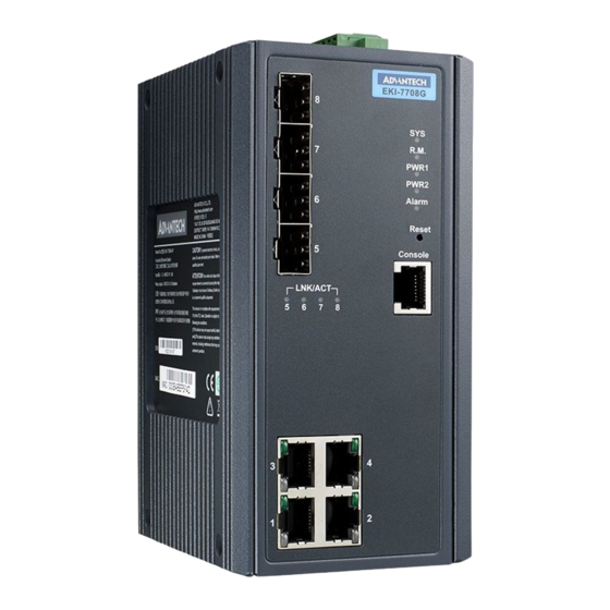
Advantech EKI-7708 Series User Manual (163 pages)
4FE/4GE + 4G SFP Port Gigabit Managed Redundant Industrial Switch 4FE/4GE PoE + 4G SFP Port Gigabit Managed Redundant Industrial PoE Switch
Brand:
Advantech
| Category:
Switch
| Size: 7 MB
Table of Contents
Table of Contents
8
Product Overview
14
Supported Models
15
Specifications
15
Hardware Views
17
Front View
17
Figure 1.1 Front View
17
Figure 1.2 Front View
18
Figure 1.3 System LED Panel
19
Figure 1.4 System LED Panel
20
Rear View
21
Figure 1.5 Rear View
21
Top View
22
Figure 1.6 Top View
22
Figure 1.7 Top View
22
Switch Installation
23
Installation Guidelines
24
Connecting Hardware
24
Verifying Switch Operation
24
Installing the Switch
24
DIN Rail Mounting
24
Figure 2.1 Installing the DIN-Rail Mounting Kit
25
Figure 2.2 Correctly Installed DIN Rail Kit
25
Wall-Mounting
26
Figure 2.3 Removing the DIN-Rail
26
Figure 2.4 Installing Wall Mount Plates
27
Figure 2.5 Securing Wall Mounting Screws
27
Figure 2.6 Wall Mount Installation
28
Installing and Removing SFP Modules
29
Installing SFP Modules
29
Figure 2.7 Removing the Dust Plug from an SFP Slot
29
Figure 2.8 Installing an SFP Transceiver
30
Figure 2.9 Attaching a Fiber Optic Cable to a Transceiver
30
Removing SFP Modules
31
Figure 2.10 Removing a Fiber Optic Cable to a Transceiver
31
Figure 2.11 Removing an SFP Transceiver
31
Connecting the Switch to Ethernet Ports
32
RJ45 Ethernet Cable Wiring
32
Figure 2.12 Ethernet Plug & Connector Pin Position
32
Connecting the Switch to Console Port
33
Figure 2.13 Serial Console Cable
33
Figure 2.14 DB 9 Pin Position
33
Figure 2.15 Pin Assignment
33
Power Supply Installation
34
Overview
34
Figure 2.16 Power Wiring for EKI-7708 Series
34
Considerations
35
Grounding the Device
35
Wiring a Relay Contact
36
Figure 2.17 Grounding Connection
36
Figure 2.18 Terminal Receptor: Relay Contact
36
Figure 2.19 Terminal Receptor: Relay Contact (Poe Model)
36
Wiring the Power Inputs
37
Figure 2.20 Terminal Receptor: Power Input Contacts
37
Figure 2.21 Removing a Terminal Block
37
Reset Button
38
Figure 2.22 Installing DC Wires in a Terminal Block
38
Figure 2.23 Securing a Terminal Block to a Receptor
38
Configuration Utility
39
First Time Setup
40
Overview
40
Introduction
40
Administrative Interface Access
40
Using the Graphical (Web) Interface
41
Configuring the Switch for Network Access
41
Configuring the Ethernet Ports
42
Command Line Interface Configuration
43
Introduction to Command-Line Interface (CLI)
43
Accessing the CLI
43
Web Browser Configuration
44
Preparing for Web Configuration
44
System Login
44
Managing Switch
45
Log in
46
Recommended Practices
46
Changing Default Password
46
Figure 4.1 Login Screen
46
Monitoring
47
Device Information
47
Figure 4.2 Changing a Default Password
47
Figure 4.3 Monitoring > Device Information
47
Logging Message
48
Figure 4.4 Monitoring > Logging Message
48
Port Monitoring
49
Figure 4.5 Monitoring > Port Monitoring > Port Statistics
49
Link Aggregation
50
Figure 4.6 Monitoring > Port Monitoring > Port Utilization
50
LLDP Statistics
51
Figure 4.7 Monitoring > LLDP Statistics
51
IGMP Statistics
52
Figure 4.8 Monitoring > IGMP Statistics
52
System
53
IP Settings
53
Figure 4.9 System > IP Settings
53
DHCP Client Option 82
54
Figure 4.10 System > DHCP Client Option 82
54
DHCP Auto Provision
55
Ipv6 Settings
55
Figure 4.11 System > DHCP Auto Provision
55
Figure 4.12 System > Ipv6 Settings
55
Management VLAN
56
Figure 4.13 System > Management VLAN
56
System Time
57
Figure 4.14 System > System Time
57
L2 Switching
58
Port Configuration
58
Figure 4.15 L2 Switching > Port Configuration
58
Port Mirror
59
Figure 4.16 L2 Switching > Port Mirror
59
Link Aggregation
60
Figure 4.17 L2 Switching > Link Aggregation > Load Balance
60
Figure 4.18 L2 Switching > Link Aggregation > LAG Management
60
Figure 4.19 L2 Switching > Link Aggregation > LAG Port Settings
61
Figure 4.20 L2 Switching > Link Aggregation > LACP Priority Settings
62
Figure 4.21 L2 Switching > Link Aggregation > LACP Port Settings
62
Q Vlan
63
Figure 4.22 L2 Switching > 802.1Q VLAN > VLAN Management
63
Figure 4.23 L2 Switching > 802.1Q VLAN > PVID Settings
64
Figure 4.24 L2 Switching > 802.1Q VLAN > Port to VLAN
65
Q-In-Q
66
Figure 4.25 L2 Switching > Q-In-Q > Global Settings
66
Figure 4.26 L2 Switching > Q-In-Q > Port Settings
67
Garp
68
Figure 4.27 L2 Switching > GARP > GARP Settings
68
Figure 4.28 L2 Switching > GARP > GVRP Settings
69
Figure 4.29 L2 Switching > GARP > GMRP Settings
69
Az EEE
70
Multicast
70
Figure 4.30 L2 Switching > 802.3Az EEE
70
Figure 4.31 L2 Switching > Multicast > Multicast Filtering
70
Figure 4.32 L2 Switching > Multicast > IGMP Snooping > IGMP Settings
71
Figure 4.33 L2 Switching > Multicast > IGMP Snooping > IGMP Querier
72
Figure 4.34 L2 Switching > Multicast > IGMP Snooping > IGMP Static Groups
72
Figure 4.35 L2 Switching > Multicast > MLD Snooping > MLD Settings
73
Figure 4.36 L2 Switching > Multicast > MLD Snooping > MLD Querier
74
Figure 4.37 L2 Switching > Multicast > MLD Snooping > MLD Static Group
74
Jumbo Frame
75
Figure 4.38 L2 Switching > Jumbo Frame
75
Spanning Tree
76
Figure 4.39 L2 Switching > Spanning Tree > STP Global Settings
76
Figure 4.40 L2 Switching > Spanning Tree > STP Port Settings
77
Figure 4.41 L2 Switching > Spanning Tree > STP Bridge Settings
78
Figure 4.42 L2 Switching > Spanning Tree > STP Port Advanced Settings
79
Figure 4.43 L2 Switching > Spanning Tree > MST Config Identification
79
Figure 4.44 L2 Switching > Spanning Tree > MST Instance ID Settings
80
Figure 4.45 L2 Switching > Spanning Tree > MST Instance Priority Settings
80
X-Ring Elite
81
Figure 4.46 L2 Switching > X-Ring Elite > X-Ring Elite Settings
81
X-Ring Pro
82
Figure 4.47 L2 Switching > X-Ring Elite > X-Ring Elite Groups
82
Figure 4.48 L2 Switching > X-Ring Pro > X-Ring Pro Settings
82
Figure 4.49 L2 Switching > X-Ring Pro > X-Ring Pro Groups > X-Ring Pro Groups Settings
83
Figure 4.50 L2 Switching > X-Ring Pro > X-Ring Pro Groups > Chain Settings
83
Figure 4.51 L2 Switching > X-Ring Pro > X-Ring Pro Groups > Couple Setting
83
Figure 4.52 L2 Switching > X-Ring Pro > X-Ring Pro Groups > Pair Settings
84
Figure 4.53 L2 Switching > X-Ring Pro > X-Ring Pro Groups > Rpair Settings
84
Loopback Detection
85
Figure 4.54 L2 Switching > Loopback Detection > Global Settings
85
Figure 4.55 L2 Switching > Loopback Detection > Port Settings
85
Cfm
86
Figure 4.56 L2 Switching > CFM > CFM Settings
86
Figure 4.57 L2 Switching > CFM > ME Groups
86
Erps
87
Figure 4.58 L2 Switching > CFM > ME Settings
87
Figure 4.59 L2 Switching > ERPS > ERPS Settings
87
Figure 4.60 L2 Switching > ERPS > ERPS Groups
87
MAC Address Table
88
Static MAC
88
Figure 4.61 MAC Address Table > Static MAC
88
MAC Aging Time
89
Dynamic Forwarding Table
89
Figure 4.62 MAC Address Table > MAC Aging Time
89
Figure 4.63 MAC Address Table > Dynamic Forwarding Table
89
Security
90
Storm Control
90
Figure 4.64 Security > Storm Control > Global Settings
90
Figure 4.65 Security > Storm Control > Port Settings
91
Port Security
92
Protected Ports
92
Figure 4.66 Security > Port Security
92
Figure 4.67 Security > Protected Ports
92
Dos Prevention
93
Figure 4.68 Security > Dos Prevention > Dos Global Settings
93
Figure 4.69 Security > Dos Prevention > Dos Port Settings
94
Applications
95
Figure 4.70 Security > Applications > TELNET
95
Figure 4.71 Security > Applications > SSH
95
Figure 4.72 Security > Applications > HTTP
96
Figure 4.73 Security > Applications > HTTPS
96
Figure 4.74 Security > 802.1X > 802.1X Settings
97
IP Security
98
Figure 4.75 Security > 802.1X > 802.1X Port Configuration
98
Figure 4.76 Security > IP Security > Global Settings
98
Figure 4.77 Security > IP Security > Entry Settings
99
Access Control List
100
Figure 4.78 Security > Access Control List > MAC ACL > Entry Settings
100
Figure 4.79 Security > Access Control List > IP ACL > Entry Settings
101
IP Source Guard
102
Figure 4.80 Security > IP Source Guard > Global Settings
102
Figure 4.81 Security > IP Source Guard > Entry Settings
102
DHCP Snooping
103
Figure 4.82 Security > DHCP Snooping > Global Settings > DHCP Snooping State Settings
103
Figure 4.83 Security > DHCP Snooping > Global Settings > DHCP Snooping Port Settings
103
Figure 4.84 Security > DHCP Snooping > Global Settings > DHCP Snooping Binding Port Settings
103
ARP Spoofing
104
Figure 4.85 Security > ARP Spoofing
104
Qos
105
General
105
Figure 4.86 Qos > General > Qos Properties
105
Figure 4.87 Qos > General > Qos Settings
106
Figure 4.88 Qos > General > Qos Scheduling
107
Figure 4.89 Qos > General > Cos Mapping
108
Figure 4.90 Qos > General > DSCP Mapping
109
Figure 4.91 Qos > General > IP Precedence Mapping
110
Qos Basic Mode
111
Figure 4.92 Qos > Qos Basic Mode > Global Settings
111
Figure 4.93 Qos > Qos Basic Mode > Port Settings
111
Rate Limit
112
Figure 4.94 Qos > Rate Limit > Ingress Bandwidth Control
112
Figure 4.95 Qos > Rate Limit > Egress Bandwidth Control
112
Figure 4.96 Qos > Rate Limit > Egress Queue
113
Bandwidth Guarantee
114
Figure 4.97 Qos > Bandwidth Guarantee > Global Settings
114
Figure 4.98 Qos > Bandwidth Guarantee > Utilzation
114
Management
115
Lldp
115
Figure 4.99 Management > LLDP > LLDP System Settings
115
Figure 4.100 Management > LLDP > LLDP Port Settings > LLDP Port Configuration
116
Figure 4.101 Management > LLDP > LLDP Port Settings > Optional Tlvs Selection
116
Figure 4.102 Management > LLDP > LLDP Port Settings > VLAN Name TLV VLAN Selection
117
Figure 4.103 Management > LLDP > LLDP Local Device Info
117
Figure 4.104 Management > LLDP > LLDP Remote Device Info
118
Figure 4.105 Management > LLDP > LLDP Overloading
118
Snmp
119
Figure 4.106 Management > SNMP > SNMP Settings
119
Figure 4.107 Management > SNMP > SNMP Community
119
Figure 4.108 Management > SNMP > Snmpv3 Settings
120
Power over Ethernet
121
Figure 4.109 Management > SNMP > SNMP Trap
121
Figure 4.110 Management > Power over Ethernet > Poe System Settings
122
Figure 4.111 Management > Power over Ethernet > Poe Port Settings
122
TCP Modbus Settings
123
Figure 4.112 Management > TCP Modbus Settings > TCP Modbus Settings
123
DHCP Server
124
Figure 4.113 Management > DHCP Server > Status Settings
124
Figure 4.114 Management > DHCP Server > Global Settings
124
Figure 4.115 Management > DHCP Server > Port Settings
125
Figure 4.116 Management > DHCP Server > Option 82 Settings
126
Figure 4.117 Management > DHCP Server > Client MAC Settings
127
Figure 4.118 Management > DHCP Server > Lease Entry
127
SMTP Client
128
Figure 4.119 Management > SMTP Client > Global Settings
128
Figure 4.120 Management > SMTP Client > Profile Settings > Profile Settings
128
Figure 4.121 Management > SMTP Client > Profile Settings > Profile Target Mail Settings
129
Figure 4.122 Management > SMTP Client > Sending Message
129
Rmon
130
Figure 4.123 Management > RMON > Rmon Statistics
130
Figure 4.124 Management > RMON > RMON History
131
Figure 4.125 Management > RMON > Rmon Alarm
132
Diagnostics
133
Cable Diagnostics
133
Figure 4.126 Management > RMON > RMON Event
133
Figure 4.127 Diagnostics > Cable Diagnostics
133
Ping Test
134
Figure 4.128 Diagnostics > Ping Test
134
Ipv6 Ping Test
135
Figure 4.129 Diagnostics > Ipv6 Ping Test
135
System Log
136
Figure 4.130 Diagnostics > System Log > Logging Service
136
Figure 4.131 Diagnostics > System Log > Local Logging
137
Figure 4.132 Diagnostics > System Log > System Log Server
138
DDM
139
Figure 4.133 Diagnostics > DDM
139
Figure 4.134 Diagnostics > DDM
139
Tools
140
IXM
140
Figure 4.135 Tools > IXM
140
Backup Manager
141
Figure 4.136 Tools > Backup Manager
141
Upgrade Manager
142
Figure 4.137 Tools > Upgrade Manager
142
Dual Image
143
Save Configuration
143
User Account
143
Figure 4.138 Tools > Dual Image
143
Figure 4.139 Tools > User Account
143
N-Key
144
Reset System
144
Reboot Device
144
Figure 4.140 Tools > N-Key
144
Modbus/Tcp Mapping
145
Modbus/Tcp Mapping Table
145
Troubleshooting
161
Troubleshooting
162
Advertisement
Advantech EKI-7708 Series User Manual (157 pages)
4FE/4GE + 4G SFP Port Gigabit Managed Redundant Industrial Switch, 4FE/4GE PoE + 4G SFP Port Gigabit Managed Redundant Industrial PoE Switch
Brand:
Advantech
| Category:
Switch
| Size: 6 MB
Table of Contents
Declaration of Conformity
3
Technical Support and Assistance
3
Warnings, Cautions, and Notes
4
Document Feedback
4
Packing List
4
Safety Instructions
5
Wichtige Sicherheishinweise
6
Table of Contents
8
List of Figures
11
Product Overview
14
Supported Models
15
Specifications
15
Hardware Views
17
Front View
17
Figure 1.1 Front View
17
Figure 1.2 Front View
18
Figure 1.3 System LED Panel
19
Figure 1.4 System LED Panel
19
Rear View
20
Figure 1.5 Rear View
20
Top View
21
Figure 1.6 Top View
21
Figure 1.7 Top View
21
Switch Installation
22
Installation Guidelines
23
Connecting Hardware
23
Verifying Switch Operation
23
Installing the Switch
23
DIN Rail Mounting
23
Figure 2.1 Installing the DIN-Rail Mounting Kit
24
Figure 2.2 Correctly Installed DIN Rail Kit
24
Wall-Mounting
25
Figure 2.3 Removing the DIN-Rail
25
Figure 2.4 Installing Wall Mount Plates
26
Figure 2.5 Securing Wall Mounting Screws
26
Figure 2.6 Wall Mount Installation
27
Installing and Removing SFP Modules
28
Installing SFP Modules
28
Figure 2.7 Removing the Dust Plug from an SFP Slot
28
Figure 2.8 Installing an SFP Transceiver
29
Figure 2.9 Attaching a Fiber Optic Cable to a Transceiver
29
Removing SFP Modules
30
Figure 2.10 Removing a Fiber Optic Cable to a Transceiver
30
Figure 2.11 Removing an SFP Transceiver
30
Connecting the Switch to Ethernet Ports
31
RJ45 Ethernet Cable Wiring
31
Figure 2.12 Ethernet Plug & Connector Pin Position
31
Connecting the Switch to Console Port
32
Figure 2.13 Serial Console Cable
32
Figure 2.14 DB 9 Pin Position
32
Figure 2.15 Pin Assignment
32
Power Supply Installation
33
Overview
33
Figure 2.16 Power Wiring for EKI-7708 Series
33
Considerations
34
Grounding the Device
34
Wiring a Relay Contact
35
Figure 2.17 Grounding Connection
35
Figure 2.18 Terminal Receptor: Relay Contact
35
Figure 2.19 Terminal Receptor: Relay Contact (Poe Model)
35
Wiring the Power Inputs
36
Figure 2.20 Terminal Receptor: Power Input Contacts
36
Figure 2.21 Removing a Terminal Block
36
Reset Button
37
Figure 2.22 Installing DC Wires in a Terminal Block
37
Figure 2.23 Securing a Terminal Block to a Receptor
37
Configuration Utility
38
First Time Setup
39
Overview
39
Introduction
39
Administrative Interface Access
39
Using the Graphical (Web) Interface
40
Configuring the Switch for Network Access
40
Configuring the Ethernet Ports
41
Command Line Interface Configuration
42
Introduction to Command-Line Interface (CLI)
42
Accessing the CLI
42
Web Browser Configuration
43
Preparing for Web Configuration
43
System Login
43
Managing Switch
44
Log in
45
Recommended Practices
45
Changing Default Password
45
Figure 4.1 Login Screen
45
Monitoring
46
Device Information
46
Figure 4.2 Changing a Default Password
46
Figure 4.3 Monitoring > Device Information
46
Logging Message
47
Figure 4.4 Monitoring > Logging Message
47
Port Monitoring
48
Figure 4.5 Monitoring > Port Monitoring > Port Statistics
48
Link Aggregation
49
LLDP Statistics
49
Figure 4.6 Monitoring > Port Monitoring > Port Utilization
49
Figure 4.7 Monitoring > LLDP Statistics
49
IGMP Statistics
50
Figure 4.8 Monitoring > IGMP Statistics
50
System
51
IP Settings
51
Figure 4.9 System > IP Settings
51
DHCP Client Option 82
52
Figure 4.10 System > DHCP Client Option 82
52
DHCP Auto Provision
53
Ipv6 Settings
53
Figure 4.11 System > DHCP Auto Provision
53
Figure 4.12 System > Ipv6 Settings
53
Management VLAN
54
Figure 4.13 System > Management VLAN
54
System Time
55
Figure 4.14 System > System Time
55
L2 Switching
56
Port Configuration
56
Figure 4.15 L2 Switching > Port Configuration
56
Port Mirror
57
Figure 4.16 L2 Switching > Port Mirror
57
Link Aggregation
58
Figure 4.17 L2 Switching > Link Aggregation > Load Balance
58
Figure 4.18 L2 Switching > Link Aggregation > LAG Management
58
Figure 4.19 L2 Switching > Link Aggregation > LAG Port Settings
59
Figure 4.20 L2 Switching > Link Aggregation > LACP Priority Settings
60
Figure 4.21 L2 Switching > Link Aggregation > LACP Port Settings
60
Q Vlan
61
Figure 4.22 L2 Switching > 802.1Q VLAN > VLAN Management
61
Figure 4.23 L2 Switching > 802.1Q VLAN > PVID Settings
62
Figure 4.24 L2 Switching > 802.1Q VLAN > Port to VLAN
63
Q-In-Q
64
Figure 4.25 L2 Switching > Q-In-Q > Global Settings
64
Figure 4.26 L2 Switching > Q-In-Q > Port Settings
65
Garp
66
Figure 4.27 L2 Switching > GARP > GARP Settings
66
Az EEE
67
Figure 4.28 L2 Switching > GARP > GVRP Settings
67
Figure 4.29 L2 Switching > 802.3Az EEE
67
Multicast
68
Figure 4.30 L2 Switching > Multicast > Multicast Filtering
68
Figure 4.31 L2 Switching > Multicast > IGMP Snooping > IGMP Settings
69
Figure 4.32 L2 Switching > Multicast > IGMP Snooping > IGMP Querier
70
Figure 4.33 L2 Switching > Multicast > IGMP Snooping > IGMP Static Groups
70
Figure 4.34 L2 Switching > Multicast > MLD Snooping > MLD Settings
71
Figure 4.35 L2 Switching > Multicast > MLD Snooping > MLD Querier
72
Figure 4.36 L2 Switching > Multicast > MLD Snooping > MLD Static Group
72
Jumbo Frame
73
Figure 4.37 L2 Switching > Jumbo Frame
73
Spanning Tree
74
Figure 4.38 L2 Switching > Spanning Tree > STP Global Settings
74
Figure 4.39 L2 Switching > Spanning Tree > STP Port Settings
75
Figure 4.40 L2 Switching > Spanning Tree > STP Bridge Settings
76
Figure 4.41 L2 Switching > Spanning Tree > STP Port Advanced Settings
77
Figure 4.42 L2 Switching > Spanning Tree > MST Config Identification
77
Figure 4.43 L2 Switching > Spanning Tree > MST Instance ID Settings
78
Figure 4.44 L2 Switching > Spanning Tree > MST Instance Priority Settings
78
X-Ring Elite
79
Figure 4.45 L2 Switching > X-Ring Elite > X-Ring Elite Settings
79
X-Ring Pro
80
Figure 4.46 L2 Switching > X-Ring Elite > X-Ring Elite Groups
80
Figure 4.47 L2 Switching > X-Ring Pro > X-Ring Pro Settings
80
Figure 4.48 L2 Switching > X-Ring Pro > X-Ring Pro Groups > X-Ring Pro Groups Settings
81
Figure 4.49 L2 Switching > X-Ring Pro > X-Ring Pro Groups > Couple Setting
81
Loopback Detection
82
Figure 4.50 L2 Switching > Loopback Detection > Global Settings
82
Figure 4.51 L2 Switching > Loopback Detection > Port Settings
82
MAC Address Table
83
Static MAC
83
Figure 4.52 MAC Address Table > Static MAC
83
MAC Aging Time
84
Dynamic Forwarding Table
84
Figure 4.53 MAC Address Table > MAC Aging Time
84
Figure 4.54 MAC Address Table > Dynamic Forwarding Table
84
Security
85
Storm Control
85
Figure 4.55 Security > Storm Control > Global Settings
85
Figure 4.56 Security > Storm Control > Port Settings
86
Port Security
87
Protected Ports
87
Figure 4.57 Security > Port Security
87
Figure 4.58 Security > Protected Ports
87
Dos Prevention
88
Figure 4.59 Security > Dos Prevention > Dos Global Settings
88
Applications
90
Figure 4.60 Security > Dos Prevention > Dos Port Settings
90
Figure 4.61 Security > Applications > TELNET
90
Figure 4.62 Security > Applications > SSH
91
Figure 4.63 Security > Applications > HTTP
91
Figure 4.64 Security > Applications > HTTPS
92
Figure 4.65 Security > 802.1X > 802.1X Settings
93
IP Security
94
Figure 4.66 Security > 802.1X > 802.1X Port Configuration
94
Figure 4.67 Security > IP Security > Global Settings
94
Figure 4.68 Security > IP Security > Entry Settings
95
Qos
96
General
96
Figure 4.69 Qos > General > Qos Properties
96
Figure 4.70 Qos > General > Qos Settings
97
Figure 4.71 Qos > General > Qos Scheduling
98
Figure 4.72 Qos > General > Cos Mapping
99
Figure 4.73 Qos > General > DSCP Mapping
100
Figure 4.74 Qos > General > IP Precedence Mapping
101
Qos Basic Mode
102
Figure 4.75 Qos > Qos Basic Mode > Global Settings
102
Figure 4.76 Qos > Qos Basic Mode > Port Settings
102
Rate Limit
103
Figure 4.77 Qos > Rate Limit > Ingress Bandwidth Control
103
Figure 4.78 Qos > Rate Limit > Egress Bandwidth Control
103
Figure 4.79 Qos > Rate Limit > Egress Queue
104
Management
105
Lldp
105
Figure 4.80 Management > LLDP > LLDP System Settings
105
Figure 4.81 Management > LLDP > LLDP Port Settings > LLDP Port Configuration
106
Figure 4.82 Management > LLDP > LLDP Port Settings > Optional Tlvs Selection
106
Figure 4.83 Management > LLDP > LLDP Port Settings > VLAN Name TLV VLAN Selection
107
Figure 4.84 Management > LLDP > LLDP Local Device Info
107
Figure 4.85 Management > LLDP > LLDP Remote Device Info
108
Figure 4.86 Management > LLDP > LLDP Overloading
108
Snmp
109
Figure 4.87 Management > SNMP > SNMP Settings
109
Figure 4.88 Management > SNMP > SNMP Community
109
Figure 4.89 Management > SNMP > SNMP User Settings
110
Power over Ethernet
111
Figure 4.90 Management > SNMP > SNMP Trap
111
Figure 4.91 Management > Power over Ethernet > Poe System Settings
112
Figure 4.92 Management > Power over Ethernet > Poe Port Settings
113
TCP Modbus
114
Figure 4.93 Management > TCP Modbus > TCP Modbus Settings
114
DHCP Server
115
Figure 4.94 Management > DHCP Server > Status Settings
115
Figure 4.95 Management > DHCP Server > Global Settings
116
Figure 4.96 Management > DHCP Server > Port Settings
117
Figure 4.97 Management > DHCP Server > Option 82 Settings
118
SMTP Client
119
Figure 4.98 Management > DHCP Server > Lease Entry
119
Figure 4.99 Management > SMTP Client > Global Settings
119
Figure 4.100 Management > SMTP Client > Profile Settings > Profile Settings
120
Figure 4.101 Management > SMTP Client > Profile Settings > Profile Target Mail Settings
120
Figure 4.102 Management > SMTP Client > Sending Message
121
Rmon
122
Figure 4.103 Management > RMON > Rmon Statistics
122
Figure 4.104 Management > RMON > RMON History
123
Figure 4.105 Management > RMON > Rmon Alarm
124
Figure 4.106 Management > RMON > RMON Event
125
Diagnostics
126
Cable Diagnostics
126
Figure 4.107 Diagnostics > Cable Diagnostics
126
Ping Test
127
Figure 4.108 Diagnostics > Ping Test
127
Ipv6 Ping Test
129
Figure 4.109 Diagnostics > Ipv6 Ping Test
129
System Log
130
Figure 4.110 Diagnostics > System Log > Logging Service
130
Figure 4.111 Diagnostics > System Log > Local Logging
131
Figure 4.112 Diagnostics > System Log > System Log Server
132
DDM
133
Figure 4.113 Diagnostics > DDM
133
Figure 4.114 Diagnostics > DDM
133
Tools
134
IXM
134
Figure 4.115 Tools > IXM
134
Backup Manager
135
Figure 4.116 Tools > Backup Manager
135
Upgrade Manager
136
Figure 4.117 Tools > Upgrade Manager
136
Dual Image
137
Save Configuration
137
User Account
137
Figure 4.118 Tools > Dual Image
137
Figure 4.119 Tools > User Account
137
Reset System
138
Reboot Device
138
Modbus/Tcp Mapping
139
Modbus/Tcp Mapping Table
139
Troubleshooting
155
Troubleshooting
156
Advertisement
Related Products
Advantech EKI-7708E-4F-AE
Advantech EKI-7708E-4FP-AE
Advantech EKI-7708G-4F-AE
Advantech EKI-7708G-4FP-AE
Advantech EKI-7708E-4FI-AE
Advantech EKI-7708E-4FPI-AE
Advantech EKI-7708G-4FI-AE
Advantech EKI-7708G-4FPI-AE
Advantech EKI-7708G-2SI-AE
Advantech EKI-7708G-2FVI-A
Advantech Categories
Motherboard
Computer Hardware
Desktop
Network Router
Touch Panel
More Advantech Manuals
Login
Sign In
OR
Sign in with Facebook
Sign in with Google
Upload manual
Upload from disk
Upload from URL