
Related Manuals for Advantech EKI-7659CPI


Summary of Contents for Advantech EKI-7659CPI
-
Page 1: User Manual
EKI-7659CPI 8+2G Combo Ports Industrial PoE Managed Redundant Gigabit Ethernet Switch User Manual... - Page 2 The documentation and the software included with this product are copyrighted 2007 by Advantech Co., Ltd. All rights are reserved. Advantech Co., Ltd. reserves the right to make improvements in the products described in this manual at any time without notice. No part of this manual may be reproduced, copied, translated or transmitted in any form or by any means without the prior written permission of Advantech Co., Ltd.
- Page 3 Because of Advantech′s high quality-control standards and rigorous testing, most of our customers never need to use our repair service. If an Advantech product is defective, it will be repaired or replaced at no charge during the warranty period. For out-of-warranty repairs, you will be billed according to the cost of replacement materials, service time and freight.
-
Page 4: Declaration Of Conformity
Step 2. Contact your distributor, sales representative, or Advantech’s customer service center for technical support if you need additional assistance. Please have the following information ready before you call: - Product name and serial number... -
Page 5: Safety Instructions
Safety Instructions 1. Read these safety instructions carefully. 2. Keep this User's Manual for later reference. 3. Disconnect this equipment from any AC outlet before cleaning. Use a damp cloth. Do not use liquid or spray detergents for cleaning. 4. For plug-in equipment, the power outlet socket must be located near the equipment and must be easily accessible. - Page 6 Safety Precaution - Static Electricity Follow these simple precautions to protect yourself from harm and the products from damage. 1. To avoid electrical shock, always disconnect the power from your PC chassis before you work on it. Don't touch any components on the CPU card or other cards while the PC is 2.
-
Page 7: Table Of Contents
2.1 LED Indicators ..........10 Table 2.1: EKI-7659CPI LED Definition ....10 2.2 Dimensions (units: mm) ........12 Figure 2.1: Front View of EKI-7659CPI ..... 12 Figure 2.2: Side View of EKI-7659CPI ...... 13 Figure 2.3: Rear View of EKI-7659CPI ...... 14 Figure 2.4: Top View of EKI-7659CPI ....... - Page 8 Figure 3.4: Command Line Interface ......27 3.1.1 Commands Level ........27 Table 3.1: Command Level ......... 27 3.1.2 Commands Set List ......... 28 Table 3.2: Commands Set List ........28 3.1.3 System Commands Set ......28 Table 3.3: System Commands Set ....... 28 3.1.4 Port Commands Set ........
- Page 9 Figure 3.13: TFTP – Update Firmware ....... 44 Figure 3.14: TFTP – Restore Configuration ....45 Figure 3.15: TFTP – Backup Configuration ....45 Figure 3.16: Syslog Configuration ......46 Figure 3.17: SMTP Configuration ....... 47 Figure 3.18: Event Configuration ........ 48 Figure 3.19: Fault Relay Alarm ........
- Page 10 Figure A.2: EIA/TIA-568B ......... 86 Figure A.3: EIA/TIA-568A ......... 86 Figure A.4: DB 9-pin female connector ...... 87 Appendix B Compatible SFP Modules ... 90 EKI-7659CPI_Manual_ed33...
- Page 11 Overview Sections include: Introduction Features Specifications Packing List Safety Precaution Chapter1...
-
Page 12: Chapter 1 Overview
1.1.1 The SFP Advantage The EKI-7659CPI’s two SFP fiber slots provide a lot of flexibility when planning and implementing a network. The slots can accept any SFP-type fiber module and these modules are designed for transmitting over distances of either 500m (multi-mode), 10km, 30km, 50km, 70km or 110km (single-mode) –... -
Page 13: Flexible Mounting
Fail LED will turn on and send an alarm through a relay output for notifying user. 1.1.5 Flexible Mounting EKI-7659CPI is compact and can be mounted on a DIN-rail or panel, so it is suitable for any space-constrained environment. 1.1.6... -
Page 14: Features
1.2 Features 2 Gigabit Copper/SFP combo ports, plus 8 Fast Ethernet ports SFP socket for Easy and Flexible Fiber Expansion Redundancy: Gigabit X-Ring (ultra high-speed recovery time<10ms), RSTP/STP (802.1w/1D) Management: Web, Telnet, Serial Console, Windows Utility and SNMP Control: VLAN/GVRP, QOS, IGMP Snooping, LACP, and Rate Limit Security: IP/MAC and port binding, DHCP Server, IP access list, 802.1x, SNMPv3 Diagnostic: Port Statistic, Port Mirroring, RMON, Trap, SNMP Alert, and Syslog Supports 48 V... -
Page 15: Specification
1.3 Specification Communications Standard IEEE 802.3, 802.3u, 802.3x, 802.3z, 802.1d IEEE 802.1w, 802.1p, 802.1Q, 802.1X, 802.3ad, 802.3af 10/100/1000Base-TX, Optional 100Base-FX, 1000Base-SX/LX/LHX/XD/ZX/EZX Transmission Distance Ethernet: Up to 100m (4-wire Cat.5e, Cat.6 RJ-45 cable suggested for Gigabit port) SFP: Up to 110km (depends on SFP) Transmission Speed Ethernet: 10/100Mbps, Auto-Negotiation Gigabit Copper: Up to 1000 Mbps... - Page 16 3.5A@12VDC (Fuse) Overload Environment -10 ~ 60 ℃ (14 ~ 140 ℉) Operating Temperature EKI-7659CPI (Wide temp.): -40~75 ℃ (-40~167 ℉) Operating Humidity 5 ~ 95% (non-condensing) -40 ~ 85 ℃ (-40~185 ℉) Storage Temperature Storage Humidity 5 ~ 95% (non-condensing)
-
Page 17: Packing List
1.4 Packing List 1 x EKI-7659CPI Industrial Managed Gigabit Ethernet Switch 1 x eAutomation Industrial Communication CD-ROM with User manual 2 x Wall Mounting Bracket and Screws 1 x DIN-rail Mounting Bracket and Screws 1 x 8-pin RJ-45 to RS-232 serial cable 1 x DC Jack Cable φ2.0/150mm... - Page 18 EKI-7659CPI_Manual_ed33...
- Page 19 Installation Sections include: LED Indicators Dimensions Mounting Network Connection Connection to a Fiber Optic Network Power Connection Chapter2...
-
Page 20: Installation
Chapter 2 Installation In this chapter, you will be given an overview of the EKI-7659CPI hardware installation procedures. 2.1 LED Indicators There are few LEDs display the power status and network status located on the front panel of EKI-7659CPI, each of them has its own specific meaning shown as below. - Page 21 A powered device is connected utilizing Power over Ethernet on the port PoE (P1 ~ P8) Green No device is connected or power forwarding fails Chapter2...
-
Page 22: Dimensions (Units: Mm)
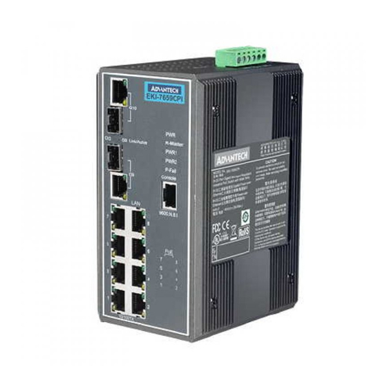
2.2 Dimensions (units: mm) Figure 2.1: Front View of EKI-7659CPI EKI-7659CPI_Manual_ed33... -
Page 23: Figure 2.2: Side View Of Eki-7659Cpi
Figure 2.2: Side View of EKI-7659CPI Chapter2... -
Page 24: Figure 2.3: Rear View Of Eki-7659Cpi
Figure 2.3: Rear View of EKI-7659CPI EKI-7659CPI_Manual_ed33... -
Page 25: Figure 2.4: Top View Of Eki-7659Cpi
Figure 2.4: Top View of EKI-7659CPI Chapter2... -
Page 26: Mounting
EKI-7659CPI can be wall-mounted by using the included mounting kit. Then, hang on the EKI-7659CPI to the nails on the wall. First, use the screws included in the package to combine the EKI-7659CPI and metal mounting kit. And then you can install the device firmly via the components, please see Figure 2.5 as below. -
Page 27: Din-Rail Mounting
The DIN-rail kit is screwed on the industrial switch when out of factory. If the DIN-rail kit is not screwed on the industrial switch, please screw the DIN-rail kit on the switch first. First, hang the EKI-7659CPI to the DIN-rail with angle of inclination. See Figure 2.6. Figure 2.6: Installation to DIN-rail Step 1... -
Page 28: Figure 2.7: Installation To Din-Rail Step 2
Then, let the device down straight to slide over the rail smoothly. See Figure 2.7. Figure 2.7: Installation to DIN-rail Step 2 EKI-7659CPI_Manual_ed33... -
Page 29: Network Connection
2.4 Network Connection The EKI-7659CPI has 8 x RJ-45 ports that support connection to 10 Mbps Ethernet, or 100 Mbps Fast Ethernet, and half or full duplex operation. EKI-7659CPI can be connected to other hubs or switches via a twisted-pair straight-through or crossover cable up to 100m long. -
Page 30: Figure 2.9: Transceiver Inserted
Figure 2.9: Transceiver Inserted Second, insert the fiber cable of LC connector into the transceiver. Figure 2.10: LC connector to the transceiver EKI-7659CPI_Manual_ed33... -
Page 31: Figure 2.11: Remove Lc Connector
To remove the LC connector from the transceiver, please follow the steps shown below: First, press the upper side of the LC connector to release from the transceiver and pull it out. Figure 2.11: Remove LC connector Second, push down the metal loop and pull the transceiver out by the plastic handle. Figure 2.12: Pull out from the transceiver Chapter2... -
Page 32: Power Connection
2.6 Power Connection The EKI-7659CPI supports dual +12 ~ 48 V power inputs and power-fail relay output. Figure 2.8: Pin Assignment of the Power Connector You can connect an alarm indicator, buzzer or other signaling equipment through the relay output. The relay opens if power input 1, 2 fails or port link down/break (″Open″... - Page 33 Chapter2...
- Page 34 Configuration Sections include: RS-232 Console Web Browser Mounting Self Diagnosis EKI-7659CPI_Manual_ed33...
-
Page 35: Configuration
Chapter 3 Configuration The EKI-7659CPI can be configured in two ways: via RS-232 Console or a web browser. 3.1 RS-232 Console EKI-7659CPI’s RS-232 console is designed for rapidly configuring which provides the console management – CLI command. Attach the supplied cable, which one end is RJ-45 and the other end is female DB9, to connect EKI- 7659CPI and your host PC or terminal. -
Page 36: Figure 3.2: Com Port Properties Setting
Select the appropriate COM port, and set the parameter as Fig.3.2 (9600 for Baud Rate, 8 for Data Bits, None for Parity, 1 for Stop Bits, and None for Flow Control). Figure 3.2: COM Port Properties Setting Press Enter for login screen (If you can not find the login screen, press Enter one more time). The default user name and password are both “admin”. -
Page 37: Figure 3.4: Command Line Interface
After you have logged in to the system, you will see a command prompt. To enter CLI management interface, type in “enable” command. Figure 3.4: Command Line Interface The following table lists the CLI commands and description. 3.1.1 Commands Level Table 3.1: Command Level Modes Access Method... -
Page 38: Commands Set List
3.1.2 Commands Set List Table 3.2: Commands Set List Command Code Word User EXEC Privileged EXEC Global configuration VLAN database Interface configuration 3.1.3 System Commands Set Table 3.3: System Commands Set Commands Level Description Example show config switch>show config Show switch configuration show terminal Show console information switch#show terminal... -
Page 39: Port Commands Set
dhcpserver subnetmask Configure subnet mask for DHCP switch(config)#dhcpserver subnetmask [Subnet mask] 255.255.255.0 clients dhcpserver gateway switch(config)#dhcpserver gateway 192.168.1.254 Configure gateway for DHCP clients [Gateway] dhcpserver dnsip Configure DNS IP for DHCP clients switch(config)#dhcpserver dnsip 192.168.1.1 [DNS IP] dhcpserver leasetime Configure lease time (in hour) switch(config)#dhcpserver leasetime 1 [Hours] dhcpserver ipbinding... -
Page 40: Trunk Commands Set
bandwidth type all Set interface ingress limit frame switch(config)#interface fastEthernet 2 switch(config-if)#bandwidth type all type to “accept all frame” bandwidth type broadcast-multicast- switch(config)#interface fastEthernet 2 Set interface ingress limit frame flooded-unicast type to “accept broadcast, switch(config-if)#bandwidth type broadcast- multicast, and flooded unicast multicast-flooded-unicast frame”... -
Page 41: Vlan Commands Set
aggregator group Assign a static trunk group. switch(config)#aggregator group 1 2-4 nolacp [GroupID] [Port-list] [GroupID] :1~3 nolacp [Port-list]:Member port list, This switch(config)#aggregator group 1 3,1,2 nolacp parameter could be a port range(ex.1-4) or a port list separate by a comma(ex.2, 3, 6) show aggregator Show the information of trunk group switch#show aggregator 1... -
Page 42: Spanning Tree Commands Set
vlan 8021q trunk Assign a access link for VLAN by switch(vlan)#vlan 8021q trunk 3 access-link untag [PortNumber] trunk group access-link untag [UntaggedVID] vlan 8021q trunk switch(vlan)#vlan 8021q trunk 3 trunk-link tag Assign a trunk link for VLAN by trunk [PortNumber] group 2,3,6,99 trunk-link tag... -
Page 43: Qos Commands Set
position as the root switch. stp-admin-p2p Admin P2P of STP priority on this switch(config)#interface fastEthernet 2 [Auto|True|False] interface. switch(config-if)#stp-admin-p2p Auto stp-admin-edge switch(config)#interface fastEthernet 2 Admin Edge of STP priority on this [True|False] interface. switch(config-if)#stp-admin-edge True stp-admin-non-stp Admin NonSTP of STP priority on switch(config)#interface fastEthernet 2 [True|False] this interface. -
Page 44: Table 3.10: Mac/Filter Table Commands Set
Table 3.10: Mac/Filter Table Commands Set Commands Level Description Example mac-address-table static hwaddr Configure MAC address table of switch(config)#interface fastEthernet 2 [MAC] interface (static). switch(config-if)#mac-address-table static hwaddr 000012345678 mac-address-table filter hwaddr Configure MAC address switch(config)#mac-address-table filter hwaddr [MAC] table(filter) 000012348678 show mac-address-table switch#show mac-address-table Show all MAC address table... -
Page 45: Port Mirroring Commands Set
sub-oid [OID] show snmp Show SNMP configuration switch#show snmp no snmp community-strings switch(config)#no snmp community-strings public Remove the specified community. [Community] no snmp-server host Remove the SNMP server host. switch(config)#no snmp-server 192.168.1.50 [Host-address] no snmpv3 user Remove specified user of SNMPv3 switch(config)#no snmpv3 user Test [User Name] agent. -
Page 46: Tftp Commands Set
change the radious server port 8021x system accountport Use the 802.1x system account switch(config)# 8021x system accountport 1816 [port ID] port global configuration command to change the accounting port 8021x system sharekey Use the 802.1x system share key switch(config)# 8021x system sharekey 123456 [ID] global configuration command to change the shared key value. -
Page 47: Sntp Commands Set
systemlog mode Specified the log mode switch(config)# systemlog mode both [client|server|both] show systemlog Switch>show systemlog Displays system log. show systemlog Show system log client & server switch#show systemlog information no systemlog Disable systemlog functon switch(config)#no systemlog smtp enable Enable SMTP function switch(config)#smtp enable smtp serverip Configure SMTP server IP... -
Page 48: X-Ring Commands Set
show sntp timezone Show index number of time zone switch#show sntp timezone list no sntp Disable SNTP function switch(config)#no sntp no sntp daylight Disable daylight saving time switch(config)#no sntp daylight 3.1.17 X-ring Commands Set Table 3.17: X-ring Commands Set Commands Level Description Example... -
Page 49: Figure 3.5: Type The Address In The Url
You can change the password in the system setting. In the main page, you can find the tree menu structure of the EKI-7659CPI in the left side. Click the “+” symbol to unroll the hiding hyperlink, and click the hyperlink to open the function page you want to configure. -
Page 50: Figure 3.7: Main
Figure 3.7: Main page 3.2.1 System System Information Here you can view the system information and assign the system name and location to make this switch more easily to be identified on your network. System Name: Assign the name of the switch. The maximum length is 64 bytes. System Description: Displays the description of switch. - Page 51 Figure 3.8: System Information IP Configuration User can configure the IP Settings and DHCP client function here. DHCP Client: To enable or disable the DHCP client function. When DHCP client function is enabled, the industrial switch will be assigned the IP address from the network DHCP server. The default IP address will be replaced by the DHCP server assigned IP address.
- Page 52 Figure 3.9: IP Configuration DHCP Server – System configuration DHCP is the abbreviation of Dynamic Host Configuration Protocol that is a protocol for assigning dynamic IP addresses to devices on a network. With dynamic addressing, a device can have a different IP address every time it connects to the network.
-
Page 53: Figure 3.11: Dhcp Server – Client Entries
Figure 3.10: DHCP Server - System Configuration DHCP Client – System Configuration When the DHCP server function is active, the system will collect the DHCP client information and displays them here. Figure 3.11: DHCP Server – Client Entries DHCP Server - Port and IP Bindings You can assign a specific IP address, which is the IP in dynamic IP assign range, to the specific port. -
Page 54: Figure 3.12: Dhcp Server – Port And Ip Binding
Figure 3.12: DHCP Server – Port and IP Binding TFTP - Update Firmware Trivial File Transfer Protocol (TFTP) is a very simple file transfer protocol, with the functionality of a very basic form of FTP. It provides the functions to allow the user to update the switch firmware. Before updating, make sure you have your TFTP server ready and the firmware image is on the TFTP server. -
Page 55: Figure 3.14: Tftp – Restore Configuration
You can restore Flash ROM value from TFTP server, but you must put the image file on TFTP server first, switch will download back flash image. TFTP Server IP Address: fill in the TFTP server IP. Restore File Name: fill in the correct restore file name. Click Apply Figure 3.14: TFTP –... -
Page 56: Figure 3.16: Syslog Configuration
Configure the system event mode and system log server IP which you want to collect. Syslog Client Mode: select the system log mode – client only, server only, or both S/C. System Log Server IP Address: assign the system log server IP. Click Reload to refresh the events log. -
Page 57: Figure 3.17: Smtp Configuration
Click Apply . Figure 3.17: SMTP Configuration System Event Log - Event Configuration You can select the ‘Syslog’ and ‘SMTP’ events for each port. When selected events occur, the system will send out the log information to the system log server. After configuring, Click Apply . System event selection: 4 selections –... -
Page 58: Figure 3.18: Event Configuration
Figure 3.18: Event Configuration Fault Relay Alarm Power Failure: Mark the check box to enable the function of lighting up FAULT LED on the panel when power fails. Port Link Down/Broken: Mark the check box to enable the function of lighting up FAULT LED on the panel when ports’... -
Page 59: Figure 3.19: Fault Relay Alarm
Figure 3.19: Fault Relay Alarm SNTP Configuration You can configure the SNTP (Simple Network Time Protocol) settings. The SNTP allows you to synchronize switch clocks on the Internet. SNTP Client: enable or disable SNTP function to get the time from the SNTP server. Daylight Saving Time: enable or disable daylight saving time function. - Page 60 MST - Mountain Standard -7 hours 5 am PDT - Pacific Daylight PST - Pacific Standard -8 hours 4 am ADT - Alaskan Daylight ALA - Alaskan Standard -9 hours 3 am HAW - Hawaiian Standard -10 hours 2 am Nome, Alaska -11 hours 1 am...
-
Page 61: Figure 3.20: Sntp Configuration
Figure 3.20: SNTP Configuration IP Security IP security function allows the user to assign 10 specific IP addresses that have permission to access the switch through the web browser for the securing switch management. IP Security Mode: when this option is in Enable mode, the Enable HTTP Server and Enable Telnet Server check boxes will then be available. -
Page 62: Figure 3.21: Ip Security
Figure 3.21: IP Security User Authentication You can change login user name and password for the management security issue. User name: Key in the new user name (The default is “admin”) Password: Key in the new password (The default is “admin”) Confirm password: Re-type the new password And then, click Apply button to apply the configuration. -
Page 63: Figure 3.22: User Authentication
Figure 3.22: User Authentication Chapter3... -
Page 64: Figure 3.23: Port Statistics
3.2.2 Port Port setting includes Port Statistics, Port Control, Port Trunk, Port Mirroring, and Rate Limiting. User can use this interface to set the parameters and control the packet flow among the ports. Port Statistics The following information provides the current port statistic information. Port: The port number. -
Page 65: Figure 3.24: Port Control
Speed: set the port link speed. Duplex: set full-duplex or half-duplex mode of the port. Flow Control: set flow control function as Enable or Disable in Full Duplex mode. The default value is Enable. Security: when its state is “On” that means this port accepts only one MAC address. Click Apply button to apply the configuration. -
Page 66: Figure 3.25: Aggregator Setting
If LACP enable, you can configure LACP Active/Passive status in each ports on State Activity page. Click Apply . Use Apply button to delete Trunk Group. Select the Group ID and click Delete button. Figure 3.25: Aggregator Setting Aggregator Information When you have set up the aggregator setting with LACP disabled, you will see the local static trunk group information here. -
Page 67: Figure 3.27: State Activity
When you had set up the LACP aggregator, you can configure port state activity. You can mark or un- mark the port. When you mark the port and click Apply button the port state activity will change to Active. Opposite is Passive. Active: The port automatically sends LACP protocol packets. -
Page 68: Figure 3.28: Port Mirroring
Figure 3.28: Port Mirroring Rate Limiting You can set up the bandwidth rate and frame limitation type for each port. Ingress Limit Frame type: select the frame type that wants to filter. The frame types have 4 options for selecting: All, Broadcast/Multicast/Flooded Unicast, Broadcast/Multicast and Broadcast only. Broadcast/Multicast/Flooded Unicast, Broadcast/Multicast and Bbroadcast only types are only for ingress frames. -
Page 69: Figure 3.29: Rate Limiting
Figure 3.29: Rate Limiting Chapter3... -
Page 70: Figure 3.30: Vlan Configuration
3.2.3 Protocol User can set the layer 2 protocol setting via this interface. VLAN configuration A Virtual LAN (VLAN) is a logical network grouping that limits the broadcast domain, which would allow you to isolate network traffic, so only the members of the VLAN will receive traffic from the same members of VLAN. -
Page 71: Figure 3.31: Port Based Mode
Figure 3.31: Port based mode Pull down the select item menu of VLAN Operation Mode, and select Port Based mode. Click to add a new VLAN group(The maximum VLAN group is up to 256 VLAN groups) Entering the VLAN name, group ID and grouping the members of VLAN group And then, click Apply Chapter3... -
Page 72: Figure 3.32: Port Based Mode-Add Interface
Figure 3.32: Port based mode-Add interface You will see the VLAN displays. Use Delete button to delete unwanted VLAN. Edit button to modify existing VLAN group. Note Remember to execute the “Save Configuration” action, otherwise the new configuration will lose when switch power off. 802.1Q VLAN Tagged-based VLAN is an IEEE 802.1Q specification standard. -
Page 73: Figure 3.33: 802.1Q Vlan Configuration
Figure 3.33: 802.1Q VLAN Configuration 802.1Q Configuration Pull down the select item menu of VLAN Operation Mode, and select Port Based mode. Enable GVRP Protocol: mark the check box to enable GVRP protocol that allows network devices to dynamically exchange VLAN configuration information with other devices. If GVRP protocol is not enabled, user has to set the tagging information manually. -
Page 74: Figure 3.34: 802.1Q Group Configuration
Figure 3.34: 802.1Q Group Configuration You can Change the VLAN group name and VLAN ID. Click Apply . Figure 3.35: 802.1Q Group Configuration-Edit EKI-7659CPI_Manual_ed33... - Page 75 Rapid Spanning Tree The Rapid Spanning Tree Protocol (RSTP) is an evolution of the Spanning Tree Protocol and provides for faster spanning tree convergence after a topology change. The system also supports STP and the system will auto detect the connected device that is running STP or RSTP protocol. RSTP - System Configuration User can view spanning tree information about the Root Bridge User can modify RSTP state.
-
Page 76: Figure 3.36: Rstp System Configuration Interface
Figure 3.36: RSTP System Configuration interface RSTP - Port Configuration You can configure the path cost and priority of each port. Select the port in Port column. Path Cost: The cost of the path to the other bridge from this transmitting bridge at the specified port. Enter a number 1 through 200000000. -
Page 77: Figure 3.38: Snmp System Configuration Interface
SNMP Configuration Simple Network Management Protocol (SNMP) is the protocol developed to manage nodes (servers, workstations, routers, switches and hubs etc.) on an IP network. SNMP enables network administrators to manage network performance, find and solve network problems, and plan for network growth. Network management systems learn of problems by receiving traps or change notices from network devices implementing SNMP. -
Page 78: Figure 3.39: Trap Configuration Interface
Trap Configuration A trap manager is a management station that receives traps, the system alerts generated by the switch. If no trap manager is defined, no traps will issue. Create a trap manager by entering the IP address of the station and a community string. -
Page 79: Figure 3.40: Snmp V3 Configuration Interface
Remove Click to remove unwanted context name. Figure 3.40: SNMP V3 configuration interface Group Table Configure SNMP v3 group table. Security Name (User ID): Assign the user name that you have set up in user table. Group Name: Set up the group name. Chapter3... - Page 80 Click Add to add context name. Click Remove to remove unwanted context name. Access Table Configure SNMP v3 access table. Context Prefix: Set up the context name. Group Name: Set up the group. Security Level: Set up the access level. Context Match Rule: Select the context match rule.
- Page 81 QoS Configuration You can configure Qos policy and priority setting, per port priority setting, COS and TOS setting. QoS Policy and Priority Type Qos Policy: select the Qos policy rule. Use an 8,4,2,1 weighted fair queuing scheme: The switch will follow 8:4:2:1 rate to process priority queue from High to Lowest queue.
-
Page 82: Figure 3.41: Qos Configuration Interface
Figure 3.41: QoS Configuration interface Port Base Priority Configure per port priority level. Port 1 ~ Port 10: each port has 4 priority levels – High, Middle, Low, and Lowest. Click Apply . COS Configuration EKI-7659CPI_Manual_ed33... -
Page 83: Table 3.19: Igmp Types
Set up the COS priority level. COS priority: Set up the COS priority level 0~7 –High, Middle, Low, Lowest. Click Apply . TOS Configuration Set up the TOS priority. TOS priority: the system provides 0~63 TOS priority level. Each level has 4 types of priority – high, middle, low, and lowest. -
Page 84: Figure 3.42: Igmp Configuration Interface
Figure 3.42: IGMP Configuration interface X-Ring X-Ring provides a faster redundant recovery than Spanning Tree topology. The action is similar to STP or RSTP, but the algorithms not the same. In the X-Ring topology, every switch should enable X-Ring function and assign two member ports in the ring. -
Page 85: Figure 3.43: X-Ring Interface
Figure 3.43: X-ring Interface Note When the X-Ring function enable, user must disable the RSTP. The X-Ring function and RSTP function cannot exist at the same time. Remember to execute the “Save Configuration” action, otherwise the new configuration will lose when switch power off. Chapter3... -
Page 86: Figure 3.44: 802.1X/Radius System Configuration
3.2.4 Security In this section, you can configure 802.1x and MAC address table. 802.1X/Radius Configuration 802.1x is an IEEE authentication specification that allows a client to connect to a wireless access point or wired switch but prevents the client from gaining access to the Internet until it provides authority, like a user name and password that are verified by a separate server. -
Page 87: Figure 3.45: 802.1X/Radius - Port Setting Interface
Figure 3.45: 802.1x/Radius - Port Setting interface 802.1X/Radius - Misc Configuration Quiet Period: set the period during which the port doesn’t try to acquire a supplicant. TX Period: set the period the port wait for retransmit next EAPOL PDU during an authentication session. -
Page 88: Figure 3.46: 802.1X/Radius - Misc Configuration
Figure 3.46: 802.1x/Radius - Misc Configuration MAC Address Table Use the MAC address table to ensure the port security. You can add a static MAC address; it remains in the switch's address table, regardless of whether the device is physically connected to the switch. This saves the switch from having to re-learn a device's MAC address when the disconnected or powered-off device is active on the network again. -
Page 89: Figure 3.48: Mac Filtering Interface
Figure 3.48: MAC Filtering interface MAC Address: Enter the MAC address that you want to filter. Click If you want to delete the MAC address from filtering table, select the MAC address and click Delete . MAC Address Table - All MAC Addresses You can view the port of the connected device’s MAC address and related devices’... -
Page 90: Figure 3.50: Poe Status
Power over Ethernet This segment shows the Power over Ethernet function. Figure 3.50: PoE Status Maximum Power Available: Displays the maximum power supply in Watt. Actual Power Consumption: This column shows the real-time total power consumption. Main Supply Voltage: This column shows the output voltage of the system for PoE ports. d means 1/10, and supply 48V when work on PoE situation. -
Page 91: Figure 3.51: Factory Default Interface
Voltage (V): Displays the operating voltage of the port. Power (mW): Displays the power consumption of the port. Apply Determined Class: Displays the PD’s class. And then, click to carry into effect. Factory Default Reset switch to default configuration. Click Reset to reset all configurations to the default value. Figure 3.51: Factory Default interface Save Configuration Save all configurations that you have made in the system. -
Page 92: Figure 3.53: System Reboot Interface
Figure 3.53: System Reboot interface Reboot the switch in software reset. Click Reboot to reboot the system. EKI-7659CPI_Manual_ed33... - Page 93 Troubleshooting...
-
Page 94: Chapter 4 Troubleshooting
Chapter 4 Troubleshooting Verify that is using the right power cord/adapter (+12~48V ), please don’t use the power adaptor with DC output voltage higher than 48 V, or it will burn this converter down. Select the proper UTP cable to construct user network. Please check that is using the right cable. - Page 95 Pin Assignment & Wiring...
-
Page 96: Figure A.1: Rj-45 Pin Assignment
Appendix A Pin Assignment & Wiring It is suggested to adopt ELA/TIA as the wiring of the RJ-45. Figure A.1: RJ-45 Pin Assignment Figure A.2: EIA/TIA-568B Figure A.3: EIA/TIA-568A EKI-7659CPI_Manual_ed33... -
Page 97: Figure A.4: Db 9-Pin Female Connector
Figure A.4: DB 9-pin female connector DB9 Connector RJ-45 Connector 1 Orange/White 2 Orange 3 Green/White 4 Blue 5 Blue/White 6 Green 7 Brown/White 8 Brown... - Page 98 EKI-7659CPI_Manual_ed33...
- Page 99 Compatible SFP Modules...
-
Page 100: Compatible Sfp Modules
Appendix B Compatible SFP Modules The table below shows compatible SFP modules for EKI-7659CPI. Transmission Item Brand Part Number Mode Distance AVAGO AFBR-5710PZ 550m APAC LM28-C3S-TC-N 550m Multi-mode HOATECH HTI8512-X5ATO 550m SPACE SHUTTLE S56L-S85-6L-N 550m SP-GB-LX 10km LuminentOIC SP-GB-ELX 20km...
Need help?
Do you have a question about the EKI-7659CPI and is the answer not in the manual?
Questions and answers