
Related Manuals for C.R. Laurence INTELLI-TRACK

Summary of Contents for C.R. Laurence INTELLI-TRACK
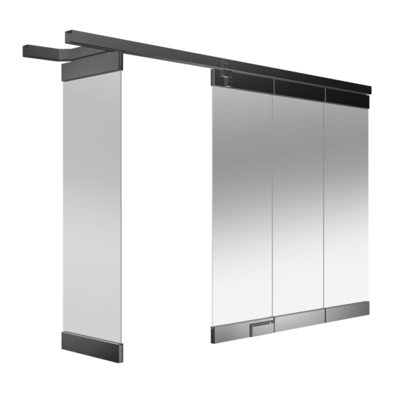
- Page 1 GLASS DRILL INSTRUCTION MANUAL INSTALLATION INSTRUCTIONS crlaurence.com INTELLI-TRACK ™ STACKING PARTITION SYSTEM C.R. Laurence Co., Inc. • 2503 E. Vernon Ave., Los Angeles, CA 90058 • 1.800.421.6144 • crlaurence.com 11M0272...
-
Page 2: Important Notes
Cutting Blade • Saw Horses (Two) The rapidly changing technology within the architectural aluminum products industry demands that C.R. Laurence/U.S. Aluminum reserve the right to revise, discontinue, or change any product line, specification, or electronic media without prior written notice. - Page 3 3. 1/4" (6.4) is the nominal clearance between the floor and bottom Wall Panel Rails; 5/16" (7.9) is the maximum recommended clearance. C.R. Laurence Co., Inc. • 2503 E. Vernon Ave., Los Angeles, CA 90058 • 1.800.421.6144 • crlaurence.com...
- Page 4 (Fig 3). SPS Door Top Pivot and Adjustable Roller Stop final adjustments will be done in Phase 2 after Track has been completely installed. Figure 3 C.R. Laurence Co., Inc. • 2503 E. Vernon Ave., Los Angeles, CA 90058 • 1.800.421.6144 • crlaurence.com...
- Page 5 NOTE: If your SPS System was ordered prefabricated, proceed to Step 3 on Page 6. Figure 5 Install the Remaining Track Components C.R. Laurence Co., Inc. • 2503 E. Vernon Ave., Los Angeles, CA 90058 • 1.800.421.6144 • crlaurence.com P. 5...
- Page 6 Use 3.8" Hex Head type fasteners made from one of the following materials: A307 Galvanized or A316 Stainless Steel. NOTE: ALWAYS USE LOCK WASHERS. C.R. Laurence Co., Inc. • 2503 E. Vernon Ave., Los Angeles, CA 90058 • 1.800.421.6144 • crlaurence.com...
- Page 7 NOTE: ALWAYS USE LOCK WASHERS. 2. Ensure a slight clearance for later removal of the Roller Access Splice. THIS FIRST PHASE OF THE INSTALLATION IS COMPLETE C.R. Laurence Co., Inc. • 2503 E. Vernon Ave., Los Angeles, CA 90058 • 1.800.421.6144 • crlaurence.com...
- Page 8 NOTE: Pivots do not have a special orientation during insertion into the Track, but Stops must be rotated such that their rubber bumpers face toward the adjacent Sliding Wall Panel. C.R. Laurence Co., Inc. • 2503 E. Vernon Ave., Los Angeles, CA 90058 • 1.800.421.6144 •...
- Page 9 Threadlocker must be applied to the threads, preventing loosening. Tighten this screw firmly as its clamping action prevents the Stop from moving (Fig 7). C.R. Laurence Co., Inc. • 2503 E. Vernon Ave., Los Angeles, CA 90058 • 1.800.421.6144 • crlaurence.com...
- Page 10 3. Using a 7/32" Hex Socket or T-Handle Hex Tool, re-attach the clamping plate. Apply the supplied Loctite Threadlocker to the threads. Tighten the ® screw firmly. C.R. Laurence Co., Inc. • 2503 E. Vernon Ave., Los Angeles, CA 90058 • 1.800.421.6144 • crlaurence.com P. 10...
-
Page 11: Phase Two
NOTE: The #1 Wall Panel is the Panel farthest from the parking area. Each component is labeled to match its designated location on the plan. C.R. Laurence Co., Inc. • 2503 E. Vernon Ave., Los Angeles, CA 90058 • 1.800.421.6144 •... - Page 12 Panel Rail profile heights, in combination with the Supporting Track (at the nominal roller height adjustment). The CRL SPS allows for plus and minus 3/16" (4.8) height adjustment from nominal, for a total of 3/8" (9.5) height adjustment. C.R. Laurence Co., Inc. • 2503 E. Vernon Ave., Los Angeles, CA 90058 • 1.800.421.6144 • crlaurence.com...
- Page 13 End Cap. Two Wall Panel Rails do not yet have End Caps, so align the edge of the glass to protrude from both ends of the Wall Panel Rail evenly. C.R. Laurence Co., Inc. • 2503 E. Vernon Ave., Los Angeles, CA 90058 • 1.800.421.6144 •...
- Page 14 Top Wall Panel Rail Socket Head Cap Screws are accessed through holes in a cover plate. Tighten all of the Socket Head Cap Screws working left to right using the 3/16" T-Handle Hex Tool. C.R. Laurence Co., Inc. • 2503 E. Vernon Ave., Los Angeles, CA 90058 • 1.800.421.6144 •...
- Page 15 Check to see that the Cylinder/Thumbturn on each side of the Door Rail operates freely before attaching the End Cap. C.R. Laurence Co., Inc. • 2503 E. Vernon Ave., Los Angeles, CA 90058 • 1.800.421.6144 • crlaurence.com...
- Page 16 1. Remove the Roller Access Splice, which is typically located in front of the first Parking Area Track intersection. Consult CPP for location. 2. Starting with Panel #1, install a pair of Intelli-Track™ Roller Assemblies into the SPS Track through the roller-access opening.
- Page 17 This can be verified by seeing that the pendant bolt is flush with the bottom of the Support Block. This should provide adequate clearance between the floor and Wall Panel for movement. C.R. Laurence Co., Inc. • 2503 E. Vernon Ave., Los Angeles, CA 90058 • 1.800.421.6144 •...
- Page 18 1. Slide the #1 Wall Panel to its proper location as indicated on the CPP. Position the Panel against the wall or pivoting door's edge. Examine the vertical and horizontal gaps and adjust as required. C.R. Laurence Co., Inc. • 2503 E. Vernon Ave., Los Angeles, CA 90058 • 1.800.421.6144 •...
- Page 19 Now re-tighten the Lateral Adjustment Locking Nuts to lock the Rollers at this location. 4. Repeat steps from Page 16, Step 2 for each Sliding Wall Panel. C.R. Laurence Co., Inc. • 2503 E. Vernon Ave., Los Angeles, CA 90058 • 1.800.421.6144 •...
- Page 20 1. Move the Panel nearest to the parking area to the parking area's double Track entrance. Working with the Roller Assembly that first enters the parking area, loosen the Lateral Adjustment Locking Nut on this end only. Carefully move the Wall Panel into the parking area until it comes to rest. Adjust the position of the Intelli-Track ™...
- Page 21 Next, slide the Panel out of the way, drill for and install the Keepers into the floor. Move the Wall Panel into position and lock it to the floor. 3. Repeat Steps 1 and 2 for all Sliding Wall Panels. C.R. Laurence Co., Inc. • 2503 E. Vernon Ave., Los Angeles, CA 90058 • 1.800.421.6144 • crlaurence.com...
- Page 22 NOTE: SPS End Caps are taller than the bottom rail's in order to match up with Top Seal System as described in the next step. Install the Top Seal System 1. Move #1 Panel into the closed position and lock. C.R. Laurence Co., Inc. • 2503 E. Vernon Ave., Los Angeles, CA 90058 • 1.800.421.6144 • crlaurence.com P. 22...
- Page 23 3. Dry-fit by placing the Base Extrusion on top of its Wall Panel Rail mate with the tape liner intact. If properly aligned with the rail's edge, it will drop down into an alignment slot. C.R. Laurence Co., Inc. • 2503 E. Vernon Ave., Los Angeles, CA 90058 • 1.800.421.6144 •...
- Page 24 Apply moderate pressure for the full length of the extrusions to set the tape. C.R. Laurence Co., Inc. • 2503 E. Vernon Ave., Los Angeles, CA 90058 • 1.800.421.6144 •...
- Page 25 7. Repeat Steps 1 through 6 for both sides of all Wall Panels in the system. The Second Phase of the installation is complete. C.R. Laurence Co., Inc. • 2503 E. Vernon Ave., Los Angeles, CA 90058 • 1.800.421.6144 • crlaurence.com...
- Page 26 Pivot Receiver. Make certain that the 3/8" set screw installed at the end of the Pivot Receiver is facing outward toward the end of the door rail. Loosen this set screw if it is visible in the pivot pin receiving hole. C.R. Laurence Co., Inc. • 2503 E. Vernon Ave., Los Angeles, CA 90058 • 1.800.421.6144 •...
- Page 27 End Cap removed. Using a 1/2" open-end wrench, tighten the 1/2" Hex Head bolt until the hardware is locked in place. 2-3/8" (60) C.R. Laurence Co., Inc. • 2503 E. Vernon Ave., Los Angeles, CA 90058 • 1.800.421.6144 • crlaurence.com P. 27...
- Page 28 Hex Drive Socket or T-Handle Hex Tool, turn the set screw clockwise until it presses firmly against the Pivot Pin. IMPORTANT NOTE: This step is critical in order to prevent the Pivot Pin from disengaging and possible door support failure. C.R. Laurence Co., Inc. • 2503 E. Vernon Ave., Los Angeles, CA 90058 • 1.800.421.6144 • crlaurence.com...
- Page 29 End Caps at this point but not the top caps. The glass should be flush with the End Cap surface. The rails must be completely tight against the glass edges before tightening the clamping system in the next step. C.R. Laurence Co., Inc. • 2503 E. Vernon Ave., Los Angeles, CA 90058 • 1.800.421.6144 •...
- Page 30 Installation Manual. Spacing will be determined by the width of the parking section Track. 6. Insert the Convertible Door into the Intelli-Track access section and slide into position. ™ C.R. Laurence Co., Inc. • 2503 E. Vernon Ave., Los Angeles, CA 90058 • 1.800.421.6144 • crlaurence.com P. 30...
- Page 31 Centering Tool NOTE: Remove cover, before adjusting.. Turn Lower Centering Gear with the Centering Tool to set the Door in Center Position. C.R. Laurence Co., Inc. • 2503 E. Vernon Ave., Los Angeles, CA 90058 • 1.800.421.6144 • crlaurence.com P. 31...
-
Page 32: Parts Identification
Lateral Stabilizer Tie Rod assembly for drops 34”- 42” Intermediate Support Rail Threaded Rod for drops less than 34” Self Drilling Screw Corner Support Plate Main Track C.R. Laurence Co., Inc. • 2503 E. Vernon Ave., Los Angeles, CA 90058 • 1.800.421.6144 • crlaurence.com P. 32... -
Page 33: Installation Procedures
NOTE: Fasteners are not included for attaching the brackets to the ceiling or roof-structure above. It is your reasonability to assure that the method of attachment is properly engineered to support the SPS system. C.R. Laurence Co., Inc. • 2503 E. Vernon Ave., Los Angeles, CA 90058 • 1.800.421.6144 •... -
Page 34: Floor Layout
Once the weight becomes stationary over the target, mark the ceiling indicating the center hole position of the Dual Rod Bracket. C.R. Laurence Co., Inc. • 2503 E. Vernon Ave., Los Angeles, CA 90058 • 1.800.421.6144 • crlaurence.com P. 34... - Page 35 Continue attaching all the system Dual Rod Brackets before proceeding to the next step. Be sure to properly orient each one before tightening the fasteners. Attachment to Concrete Surface Attachment to Steel Channel C.R. Laurence Co., Inc. • 2503 E. Vernon Ave., Los Angeles, CA 90058 • 1.800.421.6144 • crlaurence.com P. 35...
- Page 36 Intermediate Rail. Allow 1”- 2” space for the next step. 7-1/8" (181) Finished Ceiling Height C.R. Laurence Co., Inc. • 2503 E. Vernon Ave., Los Angeles, CA 90058 • 1.800.421.6144 • crlaurence.com P. 36...
- Page 37 Adjust level and height using the DRB Leveling Nuts. Split-Lock Washer Flat Washers DRB Leveling Nut NOTE: Use this hardware combination for all connections C.R. Laurence Co., Inc. • 2503 E. Vernon Ave., Los Angeles, CA 90058 • 1.800.421.6144 • crlaurence.com P. 37...
- Page 38 Tighten each locking hex nut to complete the procedure. The Stabilizers may require periodic adjustment in order to compensate for structural shifting. C.R. Laurence Co., Inc. • 2503 E. Vernon Ave., Los Angeles, CA 90058 • 1.800.421.6144 •...
- Page 39 Clean all debris from inside the track before use. The CRL Drop Track Support System allows easy adjustments while providing a rigid and secure platform for our Stacking Partition Systems. C.R. Laurence Co., Inc. • 2503 E. Vernon Ave., Los Angeles, CA 90058 • 1.800.421.6144 •...
- Page 40 Wall Panel Rail evenly. 2) The End Caps and Seal Kits for Top Wall Panel Rails are packaged separately, as they are installed in the final steps. C.R. Laurence Co., Inc. • 2503 E. Vernon Ave., Los Angeles, CA 90058 • 1.800.421.6144 •...
- Page 41 Make sure that the receiver box is centered in the unit to allow adjustment latter in either direction. Spindle Drop Bolt Dust Cover Adjustable Receiver Spindle Cover Panel Floor Receiver Body C.R. Laurence Co., Inc. • 2503 E. Vernon Ave., Los Angeles, CA 90058 • 1.800.421.6144 • crlaurence.com P. 41...
- Page 42 Bolt Block Receiver Block Upper Coordinator Assembly Right Roller Assembly Upper Coordinator Assembly Left Roller Assembly Lower Coordinator Assembly Pivot Hinge Assembly C.R. Laurence Co., Inc. • 2503 E. Vernon Ave., Los Angeles, CA 90058 • 1.800.421.6144 • crlaurence.com P. 42...
-
Page 43: Operating Procedures
3) The panel is ready to stack. NOTE: Engagement of the Spindle into the Floor Receiver must be the First In and Last Out Procedure. C.R. Laurence Co., Inc. • 2503 E. Vernon Ave., Los Angeles, CA 90058 • 1.800.421.6144 •...
Need help?
Do you have a question about the INTELLI-TRACK and is the answer not in the manual?
Questions and answers