Universal Robots e Series User Manual
Hide thumbs
Also See for e Series:
- User manual (361 pages) ,
- Manual (108 pages) ,
- Hardware manual (103 pages)
Table of Contents
Advertisement
Advertisement
Table of Contents

Related Manuals for Universal Robots e Series


Summary of Contents for Universal Robots e Series
- Page 1 Universal Robots e-Series User Manual UR5e Original instructions (en) US version...
- Page 3 Universal Robots e-Series User Manual UR5e Version 5.4 Original instructions (en) US Version...
- Page 4 The information contained herein is the property of Universal Robots A/S and shall not be reproduced in whole or in part without prior written approval of Universal Robots A/S. The information herein is subject to change without notice and should not be construed as a commitment by Universal Robots A/S. This manual is periodically reviewed and revised.
-
Page 5: Table Of Contents
Contents Preface What Do the Boxes Contain ........Important Safety Notice . - Page 6 5 Electrical Interface I-27 Introduction ..........I-27 5.1.1 Control Box Bracket .
- Page 7 EMC Test Certificate ........I-68 C Applied Standards I-69...
- Page 8 13.2.9 I/O ..........II-29 13.2.10 Hardware .
- Page 9 15.7.3 Force ..........II-80 15.7.4 Conveyor Tracking .
- Page 10 19 Log Tab II-125 19.1 Readings and Joint Load ........II-125 19.2 Date log .
-
Page 11: Preface
PolyScope, it is easy to program the robot to move the tool along a desired trajectory. With six joints and a wide scope of flexibility, Universal Robots e-Series collaborative robot arms are designed to mimic the range of motion of a human arm. Using our patented programming interface, PolyScope, it is easy to program the robot to move tools and communicate with other machines using electrical signals. -
Page 12: Important Safety Notice
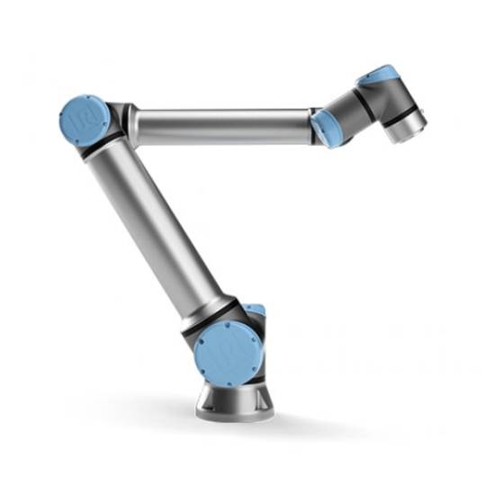
Where to Find More Information Figure 1: The joints, the base and the tool flange of the Robot Arm. • Key for opening the Control Box • Mains cable or Power cable compatible to your region • This manual Important Safety Notice The robot is partly completed machinery (see 8.4) and as such a risk assessment is required for each installation of the robot. - Page 13 Where to Find More Information • Other language versions of this manual • PolyScope Manual • The Service Manual with instructions for troubleshooting, maintenance and repair • The Script Manual for advanced users The UR+ site (http://www.universal-robots.com/plus/) is an online showroom that provides cutting-edge products to customize your UR robot application.
- Page 14 Where to Find More Information UR5e/e-Series Version 5.4...
-
Page 15: I Hardware Installation Manual
Part I Hardware Installation Manual... -
Page 17: Safety
This chapter contains important safety information, which must be read and understood by the integrator of Universal Robots e-Series robots before the robot is powered on for the first time. In this chapter, the first subsections are general. The later subsections contain specific engineering data relevant to enable setting up and programming the robot. -
Page 18: Limitation Of Liability
1.4 Warning Symbols in this Manual • Marking the robot installation with relevant signs and contact information of the integrator • Collecting all documentation in a technical file; including the risk assessment and this manual 1.3 Limitation of Liability Any safety information provided in this manual must not be construed as a warranty, by UR, that the industrial manipulator will not cause injury or damage, even if industrial manipulator complies with all safety instructions. -
Page 19: General Warnings And Cautions
1.5 General Warnings and Cautions CAUTION: This indicates a situation which, if not avoided, could result in damage to the equipment. 1.5 General Warnings and Cautions This section contains some general warnings and cautions that can be repeated or explained in different parts of this manual. - Page 20 1.5 General Warnings and Cautions WARNING: 1. Make sure the robot arm and tool/end effector are properly and securely bolted in place. 2. Make sure the robot arm has ample space to operate freely. 3. Make sure that safety measures and/or robot safety configura- tion parameters have been set up to protect both programmers, operators and bystanders, as defined in the risk assessment.
- Page 21 1.5 General Warnings and Cautions 13. Combining different machines can increase hazards or create new hazards. Always make an overall risk assessment for the complete installation. Depending on the assessed risk, differ- ent levels of functional safety can apply; as such, when different safety and emergency stop performance levels are needed, al- ways choose the highest performance level.
-
Page 22: Intended Use
1.7 Risk Assessment 1.6 Intended Use UR robots are industrial robots intended to handle tools/end effectors and fixtures, or to process or transfer components or products. For details about the environmental conditions under which the robot should operate, see appendices B and D. UR robots are equipped with special safety-related features, which are purposely designed to enable collaborative operation, where the robot system operates without fences and/or together with a human. - Page 23 (e.g. an enabling device to protect the operator during set-up and programming). Universal Robots identifies the potential significant hazards listed below as hazards that must be considered by the integrator. Note: Other significant hazards can be present in a specific robot installation.
-
Page 24: Pre-Use Assessment
Emergency stop push-buttons must comply with IEC 60947-5-5 (see section 5.4.2). 1.10 Movement Without Drive Power In the unlikely event of an emergency where any robot joints must be moved, but power to the robot is either impossible or undesired, contact your Universal Robots distributor. UR5e/e-Series I-10... -
Page 25: Safety-Related Functions And Interfaces
2 Safety-related Functions and Interfaces 2.1 Introduction Universal Robots e-Series robots are equipped with a range of built-in safety functions as well as safety I/O, digital and analog control signals to or from the electrical interface, to connect to other machines and additional protective devices. -
Page 26: Stop Categories
IEC 61800-5-2. 2.3 Configurable Safety Functions Universal Robots robot safety functions, as listed in the table below, are in the robot but are meant to control the robot system i.e. the robot with its attached tool/end effector. The robot safety functions are used to reduce robot system risks determined by the risk assessment. - Page 27 2.3 Configurable Safety Functions When performing the application risk assessment, it is necessary to take into account the motion of the robot after a stop has been initiated. In order to ease this process, the safety functions Stopping Time Limit and Stopping Distance Limit can be used. These safety functions dynamically reduces the speed of the robot motion such that it can always be stopped within the limits.
- Page 28 2.3 Configurable Safety Functions 750 mm 200 mm Figure 2.1: Due to the physical properties of the robot arm, certain workspace areas require attention regard- ing pinching hazards. One area (left) is defined for radial motions when the wrist 1 joint is at least 750 mm from the base of the robot.
- Page 29 2.3 Configurable Safety Functions Safety Input Description Emergency Stop Performs a Stop Category 1 informing other machines using Button the System Emergency Stop output, if that output is defined. Robot Emergency Performs a Stop Category 1 via Control Box input, informing Stop other machines using the System Emergency Stop output, if that output is defined.
-
Page 30: Safety Function
2.5 Modes 2.4 Safety Function The safety system acts by monitoring if any of the safety limits are violated or if an Emergency Stop or a Safeguard Stop is initiated. The reactions of the safety system are: Trigger Reaction Emergency Stop Stop Category 1. - Page 31 2.5 Modes Safety Function Limit ◦ Joint Speed Limit Speed Limit Force Limit 100 N Momentum Limit kg m Power Limit 80 W The safety system issues a Stop Category 0 if a violation of these limits appears. WARNING: Limits for the joint positions, the safety planes, and the tool/end ef- fector orientation are disabled in Recovery Mode.
- Page 32 2.5 Modes UR5e/e-Series I-18 Version 5.4...
-
Page 33: Transportation
1. Make sure not to overload your back or other bodyparts when lift- ing the equipment. Use proper lifting equipment. All regional and national lifting guidelines shall be followed. Universal Robots cannot be held responsible for any damage caused by trans- portation of the equipment. - Page 34 UR5e/e-Series I-20 Version 5.4...
-
Page 35: Mechanical Interface
4 Mechanical Interface 4.1 Introduction This chapter describes the basics of mounting the parts of the robot system. Electrical installation instructions in chapter 5 must be observed. 4.2 Workspace of the Robot The workspace of the UR5e robot extends 850 mm from the base joint. It is important to consider the cylindrical volume directly above and directly below the robot base when choosing a mounting place for the robot. - Page 36 4.3 Mounting DANGER: Make sure the Robot Arm is properly and securely bolted in place. Unstable mounting can lead to accidents. CAUTION: Mount the robot in an environment suited for the IP rating. The robot must not be operated in environments that exceed those correspond- ing to the IP ratings of the robot (IP54), Teach Pendant (IP54) and Control Box (IP44) Tool The robot tool flange has four M6 thread holes for attaching a tool to the robot.
- Page 37 4.3 Mounting Surface on which the robot is fitted 0.05 0.030 8 FG8 8.5 min. 0.008 0.024 8 FG8 X 10 8.5 min. 0.006 Figure 4.1: Holes for mounting the robot. Use four M8 bolts. All measurements are in mm. Version 5.4 I-23 UR5e/e-Series...
- Page 38 4.3 Mounting Figure 4.2: The tool output flange (ISO 9409-1-50-4-M6) is where the tool is mounted at the tip of the robot. All measures are in mm. UR5e/e-Series I-24 Version 5.4...
- Page 39 4.3 Mounting DANGER: 1. Make sure the Control Box, Teach Pendant and cables do not come into contact with liquids. A wet Control Box could cause fatal injury. 2. Place the Teach Pendant (IP54) and Control Box (IP44) in an en- vironment suited for the IP rating.
-
Page 40: Maximum Payload
4.4 Maximum Payload 4.4 Maximum Payload The maximum allowed payload of the Robot Arm depends on the center of gravity offset, see Figure 4.3. The center of gravity offset is defined as the distance between the center of the tool output flange and the center of gravity of the attached payload. -
Page 41: Electrical Interface
5 Electrical Interface 5.1 Introduction This chapter describes electrical interface groups for the Robot Arm in the Control Box. Examples are given for most types of I/O. The term I/O refers to both digital and analog control signals to or from the electrical interface groups listed below. -
Page 42: Electrical Warnings And Cautions
5.3 Electrical Warnings and Cautions Replace the cap at the base of the Control Box with an appropriate cable gland to connect the cable to the Ethernet port. The electrical specifications are shown in the table below. Parameter Unit Communication speed 1000 Mb/s 5.3 Electrical Warnings and Cautions... - Page 43 1. Make sure all equipment not rated for water exposure remain dry. If water is allowed to enter the product, lockout-tagout all power and then contact your local Universal Robots service provider for assistance. 2. Only use the original cables supplied with the robot only. Do not use the robot for applications where the cables are subject to flexing.
-
Page 44: Controller I/O
EMC problems are found to happen usually in welding processes and are normally prompted by error messages in the log. Universal Robots cannot be held responsible for any dam- ages caused by EMC problems. 2. I/O cables going from the Control Box to other machinery and factory equipment may not be longer than 30m, unless addi- tional tests are performed. -
Page 45: Common Specifications For All Digital I/O
5.4 Controller I/O Yellow with red text Dedicated safety signals Yellow with black text Configurable for safety Gray with black text General purpose digital I/O Green with black text General purpose analog I/O In the GUI, you can set up configurable I/O as either safety-related I/O or general purpose I/O (see part II). - Page 46 5.4 Controller I/O The digital I/O are constructed in compliance with IEC 61131-2. The electrical specifications are shown below. Terminals Parameter Unit Digital Outputs [COx / DOx] Current* [COx / DOx] Voltage drop [COx / DOx] Leakage current [COx / DOx] Function Type [COx / DOx]...
- Page 47 5.4 Controller I/O Emergency Stop Safeguard Stop Robot stops moving Program execution Pauses Pauses Drive power Reset Manual Automatic or manual Frequency of use Infrequent Every cycle to infrequent Requires re-initialization Brake release only Stop Category (IEC 60204-1) Performance level of monitoring function (ISO 13849-1) Use the configurable I/O to set up additional safety I/O functionality, e.g.
- Page 48 5.4 Controller I/O Safety Connecting emergency stop buttons Most applications require one or more extra emergency stop buttons. The illustration below shows how one or more emergency stop buttons can be connected. Safety Safety Sharing the Emergency Stop with other machines You can set up a shared emergency stop function between the robot and other machines by con- figuring the following I/O functions via the GUI.
- Page 49 5.4 Controller I/O Safety This configuration is only intended for applications where the operator cannot go through the door and close it behind him. The configurable I/O is used to setup a reset button outside the door to reactivate robot motion. Another example where automatic resume is appropriate is when using a safety mat or a safety- related laser scanner (see below).
- Page 50 The illustration below shows how to connect a Three-Position Enabling Device. See section 12.2 for more about Three-Position Enabling Device. NOTE: The Universal Robots safety system does not support multiple Three- Position Enabling Devices. NOTE: The two input channels for the Three-Position Enabling Device input have a disagreement tolerance of 1 second.
- Page 51 5.4 Controller I/O 5.4.3 General purpose digital I/O This section describes the general purpose 24V I/O (Gray terminals) and the configurable I/O (Yel- low terminals with black text) when not configured as safety I/O. The common specifications in section 5.4.1 must be observed. The general purpose I/O can be used t o drive equipment like pneumatic relays directly or for com- munication with other PLC systems.
- Page 52 5.4 Controller I/O Digital Inputs Digital Outputs Digital Inputs Digital Outputs 5.4.6 General purpose analog I/O The analog I/O interface is the green terminal. It is used to set or measure voltage (0-10V) or current (4-20mA) to and from other equipment. The following directions is recommended to achieve the highest accuracy.
-
Page 53: Remote On/Off Control
5.4 Controller I/O Using an Analog Output This example illustrates controlling a conveyor belt with an analog speed control input. Analog Power Using an Analog Input This example illustrates connecting an analog sensor. Analog Power 5.4.7 Remote ON/OFF control Use remote ON/OFF control to turn the Control Box on and off without using the Teach Pendant. It is typically used: •... -
Page 54: Mains Connection
5.5 Mains Connection Terminals Parameter Unit [12V - GND] Voltage [12V - GND] Current [ON / OFF] Inactive voltage [ON / OFF] Active voltage [ON / OFF] Input current [ON] Activation time Remote ON button This example illustrates connecting a remote ON button. Remote Remote OFF button This example illustrates connecting a remote OFF button. - Page 55 5.5 Mains Connection The mains supply is equipped with the following: • Connection to ground • Main fuse • Residual current device It is recommended to install a main switch to power off all equipment in the robot application as an easy means for lockout-tagout under service.
-
Page 56: Robot Connection
5.6 Robot Connection DANGER: 1. Ensure the robot is grounded correctly (electrical connection to ground). Use the unused bolts associated with grounding sym- bols inside the Control Box to create common grounding of all equipment in the system. The grounding conductor shall have at least the current rating of the highest current in the system. -
Page 57: Tool I/O
5.7 Tool I/O CAUTION: 1. Do not disconnect Robot Cable when Robot Arm is turned on. 2. Do not extend or modify original cable. 5.7 Tool I/O Adjacent to the tool flange on Wrist #3, there is an eight-pinned connector that provides power and control signals for different grippers and sensors that can be attached to the robot. -
Page 58: Tool Power Supply
5.7 Tool I/O Set the internal power supply to 0V, 12V or 24V in the I/O tab of the GUI (see part II). The electrical specifications are shown below: Parameter Type Unit Supply voltage in 24V mode 23.5 24.8 Supply voltage in 12V mode 11.5 12.5 Supply current in both modes*... -
Page 59: Tool Digital Outputs
5.7 Tool I/O NOTE: Once the robot makes an Emergency Stop, the voltage is set to 0V for both Power Pins (power is off). 5.7.2 Tool Digital Outputs Digital Outputs support three different modes: Mode Active Inactive Sinking (NPN) Open Sourcing (PNP) High Open... -
Page 60: Tool Digital Inputs
5.7 Tool I/O POWER It is recommended to use a protective diode for inductive loads, as shown below. POWER 5.7.3 Tool Digital Inputs The Digital Inputs are implemented as PNP with weak pull-down resistors. This means that a floating input always reads as low. The electrical specifications are shown below. Parameter Type Unit... -
Page 61: Tool Communication I/O
5.7 Tool I/O Two examples of using Analog Input are shown in the following subsections. CAUTION: 1. Analog Inputs are not protected against overvoltage in current mode. Exceeding the limit in the electrical specification can cause permanent damage to the input. Using Tool Analog Inputs, Nondifferential This example shows an analog sensor connection with a nondifferential output. - Page 62 5.7 Tool I/O UR5e/e-Series I-48 Version 5.4...
-
Page 63: Maintenance And Repair
Manuals on the support website http://www.universal-robots.com/support. Only authorized system integrators, or Universal Robots, shall perform repairs. All parts returned to Universal Robots shall be returned according to the service manual. 6.1 Safety Instructions After maintenance and repair work, checks must be done to ensure the required safety level. Checks must adhere to valid national or regional work safety regulations. - Page 64 6.1 Safety Instructions DANGER: 1. Remove the mains input cable from the bottom of the control box to ensure that it is completely unpowered. Deenergize any other source of energy connected to the robot arm or control box. Take necessary precautions to prevent other persons from energizing the system during the repair period.
-
Page 65: Disposal And Environment
VI, polybrominated biphenyls and polybrominated diphenyl ethers. Fee for disposal and handling of electronic waste of Universal Robots e-Series robots sold on the Danish market is prepaid to DPA-system by Universal Robots A/S. Importers in countries covered by the European WEEE Directive 2012/19/EU must make their own registration to the national WEEE register of their country. - Page 66 UR5e/e-Series I-52 Version 5.4...
-
Page 67: Certifications
Third party certification is voluntary. However, to provide the best service to robot integrators, UR chooses to certify our robots at the following recognized test institutes: TÜV NORD Universal Robots e-Series robots are safety ap- proved by TÜV NORD, a notified body under the ma- chinery directive 2006/42/EC in EU. You can find a copy of the TÜV NORD safety approval certificate in... -
Page 68: Supplier Third Party Certification
UR robots are certified according to the directives listed below. 2006/42/EC — Machinery Directive (MD) According to the Machinery Directive 2006/42/EC, Universal Robots e-Series robots are partly com- pleted machinery, as such a CE mark is not affixed. If the UR robot is used in a pesticide application, you must note the presence of directive 2009/127/EC. -
Page 69: Warranties
Ownership of devices or components replaced by and returned to Universal Robots shall vest in Universal Robots. Any other claims resulting out of or in connection with the device shall be excluded from this Warranty. Nothing in this Warranty shall attempt to limit or exclude a Customer’s Statutory Rights nor the manufacturer’s liability for death or personal injury resulting from its negli-... -
Page 70: Disclaimer
Universal Robots continues to improve reliability and performance of its products, and therefore reserves the right to upgrade the product without prior warning. Universal Robots takes every care that the contents of this manual are precise and correct, but takes no responsibility for any errors or missing information. -
Page 71: A Stopping Time And Stopping Distance
A Stopping Time and Stopping Distance NOTE: You can set user-defined safety rated maximum stopping time and distance. See 2.1 and 13.2. If user-defined settings are used, the program speed is dynamically adjusted to always comply with the se- lected limits. The graphical data provided for Joint 0 (base), Joint 1 (shoulder) and Joint 2 (elbow) is valid for stopping distance and stopping time: •... - Page 72 (a) Stopping distance in meters for 33% of maximum pay- (b) Stopping distance in meters for 66% of maximum pay- load load (c) Stopping distance in meters for maximum payload Figure A.1: Stopping distance for joint 0 (BASE) (a) Stopping time in seconds for 33% of maximum pay- (b) Stopping time in seconds for 66% of maximum pay- load load...
- Page 73 (a) Stopping distance in meters for 33% of maximum pay- (b) Stopping distance in meters for 66% of maximum pay- load load (c) Stopping distance in meters for maximum payload Figure A.3: Stopping distance for joint 1 (SHOULDER) (a) Stopping time in seconds for 33% of maximum pay- (b) Stopping time in seconds for 66% of maximum pay- load load...
- Page 74 (a) Stopping distance in meters for all payloads (b) Stopping time in seconds for all payloads Figure A.5: Stopping distance and time for joint 2 (ELBOW) UR5e/e-Series I-60 Version 5.4...
-
Page 75: B Declarations And Certificates
Serial Number: Starting 20185000000 and higher — Effective 1 April 2018 Incorporation: Universal Robots UR3e, UR5e, and UR10e shall only be put into service upon being integrated into a final com- plete machine (robot system, cell or application), which conforms with the provisions of the Machinery Directive and other ap- plicable Directives. - Page 76 B.1 EU Declaration of Incorporation in accordance with ISO/IEC 17050-1:2010 Reference the harmonized standards used: (I) EN ISO 10218-1:2011 (I) EN ISO 13850:2015 (II) EN 60664-1:2007 TUV Nord Cert. 4420714097607 (I) EN 1037:1995+A1:2008 (II) 60947-5- 5:1997/A11:2013 (I) EN ISO 12100:2010 (II) 60204-1:2006/A1:2010 (III) EN 61000-6-2:2005 (I) EN ISO 13732-1:2008...
-
Page 77: Safety System Certificate
Z E R T I F I K A T C E R T I F I C A T E Hiermit wird bescheinigt, dass die Firma / This certifies that the company Universal Robots A/S Energivej 25 DK-5260 Odense S... - Page 78 Universal Robots A/S Fertigungsstätte: Manufacturing plant: Energivej 25 DK-5260 Odense S Denmark Universal Robots Safety System G5 Beschreibung des Produktes (Details s. Anlage 1) for UR10e, UR5e and UR3e robots Description of product (Details see Annex 1) EN ISO 13849-1:2015, Cat.3, PL d Geprüft nach:...
-
Page 79: China Rohs
B.3 China RoHS B.3 China RoHS Version 5.4 I-65 UR5e/e-Series... -
Page 80: Kcc Safety
B.4 KCC Safety B.4 KCC Safety UR5e/e-Series I-66 Version 5.4... -
Page 81: Environmental Test Certificate
B.5 Environmental Test Certificate B.5 Environmental Test Certificate Climatic and mechanical assessment Client Force Technology project no. Universal Robots A/S 117-32120 Energivej 25 5260 Odense S Denmark Product identification UR 3 robot arms UR 3 control boxes with attached Teach Pendants. - Page 82 CEN/CENELEC, IEC/CISPR and ETSI. This attestation of conformity with the below mentioned standards and/or normative documents is based on accredited tests and/or technical assessments carried out at DELTA – a part of FORCE Technology. Client Universal Robots A/S Energivej 25 5260 Odense Denmark Product identification (type(s), serial no(s).)
- Page 83 C Applied Standards This section describes relevant standards applied under the development of the robot arm and control box. Whenever a European Directive number is noted in brackets, it indicates that the standard is harmonized according to that Directive. A standard is not a law. A standard is a document developed by stakeholders within a given industry, defining the normal safety and performance requirements for a product or product group.
- Page 84 The language is changed from British English to American English, but the content is the same. Note that part two (ISO 10218-2) of this standard is intended for the integrator of the robot system, and not Universal Robots. CAN/CSA-Z434-14 Industrial Robots and Robot Systems – General Safety Requirements This Canadian standard is the ISO standards ISO 10218-1 (see above) and -2 combined into one document.
- Page 85 IEC 61000-6-2:2005 IEC 61000-6-4/A1:2010 EN 61000-6-2:2005 [2004/108/EC] EN 61000-6-4/A1:2011 [2004/108/EC] Electromagnetic compatibility (EMC) Part 6-2: Generic standards - Immunity for industrial environments Part 6-4: Generic standards - Emission standard for industrial environments These standards define requirements for the electrical and electromagnetic disturbances. Conforming to these standards ensures that the UR robots perform well in industrial environments and that they do not disturb other equipment.
- Page 86 IEC 60947-5-5/A1:2005 EN 60947-5-5/A11:2013 [2006/42/EC] Low-voltage switchgear and controlgear Part 5-5: Control circuit devices and switching elements - Electrical emergency stop device with mechanical latching function The direct opening action and the safety lock mechanism of the emergency stop button comply with require- ments in this standard.
- Page 87 this standard. IEC 61140/A1:2004 EN 61140/A1:2006 [2006/95/EC] Protection against electric shock – Common aspects for installation and equipment UR robots are constructed in compliance with this standard to provide protection against electrical shock. A protective earth/ground connection is mandatory, as defined in the Hardware Installation Manual. IEC 60068-2-1:2007 IEC 60068-2-2:2007 IEC 60068-2-27:2008...
- Page 88 IEC 60664-1:2007 IEC 60664-5:2007 EN 60664-1:2007 [2006/95/EC] EN 60664-5:2007 Insulation coordination for equipment within low-voltage systems Part 1: Principles, requirements and tests Part 5: Comprehensive method for determining clearances and creepage distances equal to or less than 2 The electrical circuitry of UR robots is designed in compliance with this standard. UR5e/e-Series I-74 Version 5.4...
- Page 89 D Technical Specifications Robot type UR5e Weight 20.7 kg / 45.7 lb Maximum payload 5 kg / 11 lb (4.4) Reach 850 mm / 33.5 in ◦ ± 360 Joint ranges for all joints ◦ Speed Joints: Max 180 Tool: Approx. 1 / Approx.
- Page 90 UR5e/e-Series I-76 Version 5.4...
- Page 91 Part II PolyScope Manual...
- Page 93 10 Introduction 10.1 PolyScope Basics PolyScope is the Graphical User Interface (GUI) on the Teach Pendant that operates the Robot Arm, Control Box and executes programs. A : Header with tabs/icons that make interactive screens available to you. B : Footer with buttons that control your loaded program/s. C : Screen with fields that manage and monitor robot actions.
- Page 94 10.1 PolyScope Basics Move controls and/or regulates robot movement. I/O monitors and sets live Input/Output signals to and from robot control box. Log indicates robot health as well as any warning or error messages. Program and Installation Manager selects and displays active program and installation (see 20.4). Note: File Path, New, Open and Save make up the Program and Installation Manager.
- Page 95 10.2 Getting Started Screen 10.1.2 Footer Buttons Initialize manages robot state. When RED, press it to make the robot opera- tional. Speed Slider shows in real time the relative speed at which the robot arm moves, taking safety settings into account. Simulation button toggles a program execution between Simulation Mode and the Real Robot.
- Page 96 10.2 Getting Started Screen Run a Program, Program the Robot or Configure Robot Installation. e-Series II-6 Version 5.4...
- Page 97 11 Quick Start 11.1 Robot Arm Basics The Universal Robot arm is composed of tubes and joints. You use the PolyScope to coordinate the motion of these joints, moving the robot and positioning its tool as desired - except for the area directly above and directly below the base.
- Page 98 11.1 Robot Arm Basics 11.1.2 Turning Control Box On/Off The Control Box mainly contains the physical electrical Input/Output that connects the Robot arm, the Teach Pendant and any peripherals. You must turn on the Control Box to be able to power on the Robot arm.
- Page 99 11.2 Quick System Start-up 11.1.4 Initializing the Robot Arm DANGER: Always verify the actual payload and installation are correct before starting up the Robot arm. If these settings are incorrect, the Robot arm and Control Box will not function correctly and may become dan- gerous to people or equipment.
- Page 100 9. Tap the Start button, for the robot to release its brake system. Note: Robot vibrates and makes clicking sounds indicating it is ready to be programmed. NOTE: You can learn to program your robot on Universal Robots Academy at www.universal-robots.com/academy/ 11.3 Robot Registration and URCap License files Before using the Remote TCP URCap, register the robot and download and install the URCap License File (see 15.8).
- Page 101 11.3 Robot Registration and URCap License files 2. Copy the license file to the USB and connect it to the Teach Pendant. 3. On the Settings screen, in Step 3, tap Load file to open the Select registration file screen. 4.
- Page 102 11.3 Robot Registration and URCap License files e-Series II-12 Version 5.4...
- Page 103 *** If a Three-Position Enabling Device is configured, the robot operates at Manual Reduced Speed unless Manual High Speed is activated. NOTE: • A Universal Robots robot is not equipped with a Three-Position Enabling Device. If the risk assessment requires the device, it must be attached before the robot is used.
- Page 104 12.1 Operational Modes WARNING: • Any suspended safeguards must be returned to full functionality before selecting Automatic Mode. • Wherever possible, the Manual Mode of operation shall be per- formed with all persons outside the safeguard space. • The device used to switch between Operational Modes must be placed outside the safeguarded space.
- Page 105 12.2 Three-Position Enabling Device 12.2 Three-Position Enabling Device When a Three-Position Enabling Device is configured and the Operational Mode is in Manual Mode, the robot can only be moved by pressing the Three-Position Enabling Device. The Three-Position Enabling Device has no effect in Automatic Mode. NOTE: A connected Three-Position Enabling Device must comply with ISO 10218-1: article 5.8.3 for an enabling device.
- Page 106 12.2 Three-Position Enabling Device e-Series II-16 Version 5.4...
- Page 107 13 Safety Configuration 13.1 Safety Settings Basics This section covers how to access the robot safety settings. It is made up of items that help you set up the robot Safety Configuration. DANGER: Before you configure your robot safety settings, your integrator must conduct a risk assessment to guarantee the safety of personnel and equipment around the robot.
- Page 108 13.1 Safety Settings Basics You can find more safety system information in the Hardware Installation Manual. 13.1.2 Setting a Safety Password You must set a password to Unlock all safety settings that make up your Safety Configuration. Note: If no safety password is applied, you are prompted to set it up. 1.
- Page 109 13.2 Safety Menu Settings 3. Verify that the settings are applied. 4. Place following text in the operators’ manuals: “Before working near the robot, make sure that the safety configuration is as expected. This can be verified e.g. by inspecting the safety checksum in the top right corner of PolyScope for any changes.”...
- Page 110 13.2 Safety Menu Settings 2. Custom is where you can set Limits on how the robot functions and monitor the associated Tolerance. Power limits maximum mechanical work produced by the robot in the environment. Note: this limit considers the payload a part of the robot and not of the environment. Momentum limits maximum robot momentum.
- Page 111 13.2 Safety Menu Settings NOTE: You can switch back to Factory Presets for all robot limits to reset to their default settings. 13.2.2 Safety Modes Under normal conditions, i.e. when no protective stop is in effect, the safety system operates in a Safety Mode associated with a set of safety limits: Normal mode is the safety mode that is active by default Reduced mode is active when the robot Tool Center Point (TCP) is positioned beyond a Trigger...
- Page 112 13.2 Safety Menu Settings The menu of the Safety Configuration screen enables the user to define separate sets of safety limits for Normal and Reduced mode. For the tool and joints, Reduced mode limits for speed and momentum are required to be more restrictive than their Normal mode counterparts. 13.2.3 Tolerances In the Safety Configuration the safety system limits are specified.
- Page 113 13.2 Safety Menu Settings 13.2.5 Planes NOTE: Configuring planes is entirely based on features. We recommend you create and name all features before editing the safety configuration, as the robot is powered off once the Safety Tab has been unlocked and moving the robot will be impossible.
- Page 114 13.2 Safety Menu Settings Reduced When the safety system is in Reduced mode, a reduced mode plane is active and it acts as a strict limit on the position. Normal & Reduced When the safety system is either in Normal or Reduced mode, a normal and reduced mode plane is active and acts as a strict limit on the position.
- Page 115 13.2 Safety Menu Settings Color Codes Gray Plane is configured but disabled (A) Yellow & Black Normal Plane (B) Blue & Green Trigger Plane (C) Black Arrow The side of the plane the tool and/or elbow is allowed to be on (For Normal Planes) Green Arrow The side of the plane the tool and/or elbow is allowed to be on (For Trigger Planes) Gray Arrow The side of the plane the tool and/or elbow is allowed to be on (For Disabled Planes) 13.2.6 Freedrive...
- Page 116 13.2 Safety Menu Settings 1. On the Initialize screen, tap ON to start the power up sequence. 2. When the robot state is Idle, press and hold the Freedrive button. The robot state changes to Backdrive. 3. Brakes are only released in the joints to which significant pressure is applied. As long as the Freedrive button is engaged/pressed.
- Page 117 13.2 Safety Menu Settings Position to change the position of the tool with respect to the tool flange of the robot. The position is considered for the safety functions for tool speed, tool force, stopping distance and safety planes. You can use an existing Tool Center Point as a base for defining new tool positions. A copy of the existing TCP, predefined in General menu, in TCP screen, can be accessed in Tool Position menu, in Copy TCP drop-down list.
- Page 118 13.2 Safety Menu Settings specifying tilt and pan angles. Before configuring the limit, you must define a point or plane in the robot installation (see 16.3). The feature can then be copied and its Z axis used as the center of the cone defining the limit. NOTE: Configuration of the tool direction is based on features.
- Page 119 13.2 Safety Menu Settings Tool Properties By default, the tool points in the same direction as the Z axis of the tool output flange. This can be modified by specifying two angles: Tilt angle: How much to tilt the Z axis of the output flange towards the X axis of the output flange Pan angle: How much to rotate the tilted Z axis around the original output flange Z axis.
- Page 120 13.2 Safety Menu Settings Safeguard Reset When a Safeguard Stop occurs, this output ensures that the Safeguard Stop state continues until a reset is triggered. Automatic Mode Safeguard Stop Once configured, an Automatic Mode Safeguard Stop performs a Safeguard Stop when the input pins are low and the robot is in Automatic mode. Automatic Mode Safeguard Reset When an Automatic Mode Safeguard Stop occurs, the robot re- mains safeguard stopped in Automatic Mode until a rising edge on the input pins trigger a reset.
- Page 121 13.2 Safety Menu Settings NOTE: Any external machinery receiving its Emergency Stop state from the robot through the System Emergency Stop output must comply with ISO 13850. This is particularly necessary in setups where the Robot Emergency Stop input is connected to an external Emergency Stop device.
- Page 122 13.2 Safety Menu Settings Syncing from Home 1. In the Header, tap Installation. 2. In the Side Menu on the left of the screen, tap Safety and select Safe Home. 3. Under Safe Home, tap Sync from Home. 4. Tap Apply and in the dialog box that appears, select Apply and restart. Safe Home Output The Safe Home Position must be defined before the Safe Home Output (see 13.2.9).
- Page 123 13.2 Safety Menu Settings 4. In the Side Menu, under Safety, select Safe Home. Note: a Safety password is required to Unlock the Safety Settings (See 13.1.2). 5. Under Safe Home, tap Sync from Home Version 5.4 II-33 e-Series...
- Page 124 13.2 Safety Menu Settings e-Series II-34 Version 5.4...
- Page 125 14 Run Tab The Run tab allows you to simply operate the robot arm and control box, using as few buttons and options as possible. You can combine simple operation with password protecting the programming part of PolyScope (see 21.3.2), to make the robot into a tool that can run exclusively pre-written programs.
- Page 126 14.4 Move Robot into Position value after the robot and control box has been rebooted. Regular program variables These are available to the running program only and their values are lost as soon as the program is stopped. Show waypoints The robot program uses script variables to store information about waypoints. Select the Show Waypoints checkbox, under Variables to show script variables in the variables list.
- Page 127 14.4 Move Robot into Position Auto Hold down the Auto tab to move the robot arm to its start position. Note: You can release the button to stop the motion at any time. Animation The animation shows the movement the robot arm is about to perform when you hold down the Auto tab.
- Page 128 14.4 Move Robot into Position e-Series II-38 Version 5.4...
- Page 129 15 Program Tab The program tab shows the current program being edited. 15.1 Program Tree By tapping Command you add Program Nodes to the Program Tree. Configure the functionality of the added Program Nodes on the right side of the screen. An empty Program Tree is not allowed to run.
- Page 130 15.1 Program Tree 15.1.1 Program Execution Indication When the program is running, the Programe NOde currently being executed is indicated by a small icon next to the node. Furthermore, the path of execution is highlighted using a blue color. Pressing the icon at the corner of the program will make it track the command bring executed.
- Page 131 15.1 Program Tree Paste button allows you to paste a node that was previously cut or copied. Delete Tap the button to remove a node from the Program Tree. Suppress Tap the button to suppress specific nodes on the Program Tree. Suppressed program lines are simply skipped when the program is run.
- Page 132 15.2 Command Tab 15.1.5 Empty Node Program Nodes cannot be empty. All lines must be specified and defined in the Program Tree for a program to run. 15.2 Command Tab This manual does not cover all the details about every type of Program Node. The Robot Program Node includes three check-boxes controlling the overall behavior of the program.
- Page 133 15.3 Graphics Tab Add Before Start Sequence Select this check-box to add a special section to the program which is once when the program starts. Set Initial Variables Values Select this to set initial values of program variables. 1. Select a variable from the dropdown list, or by use the variable selector box. 2.
- Page 134 15.4 Variables Tab robot arm shows how the robot arm intends to reach the waypoint selected in the left hand side of the screen. If the current position of the robot TCP comes close to a safety or trigger plane, or the orientation 13.2.5), a 3D representation of the of robot tool is near the tool orientation boundary limit (see boundary limit is shown.
- Page 135 15.5 Basic program nodes 15.5 Basic program nodes 15.5.1 Move The Move command controls the robot motion through the underlying waypoints. Waypoints have to be under a Move command. The Move command defines the acceleration and the speed at which the robot arm will move between those waypoints.
- Page 136 15.5 Basic program nodes • Circle move can be added to a moveP to make a circular movement. The robot starts the movement from its current position or start point, moves through a ViaPoint specified on the circular arc, and an EndPoint that completes the circular movement. A mode is used to calculate tool orientation, through the circular arc.
- Page 137 15.5 Basic program nodes Cruise Deceleration Acceleration Time Figure 15.1: Speed profile for a motion. The curve is divided into three segments: acceleration, cruise and deceleration. The level of the cruise phase is given by the speed setting of the motion, while the steepness of the acceleration and deceleration phases is given by the acceleration parameter.
- Page 138 15.5 Basic program nodes Fixed Waypoint A point on the robot path. Waypoints are the most central part of a robot program, telling the robot arm where to be. A fixed position waypoint is taught by physically moving the robot arm to the position.
- Page 139 15.5 Basic program nodes Setting the waypoint Waypoint names Waypoints automatically get a unique name. The name can be changed by the user. By selecting the link icon, waypoints are linked and share position information. Other waypoint information such as blend radius, tool/joint speed and tool/joint acceleration is configured for individual waypoints even though they may be linked.
- Page 140 15.5 Basic program nodes Blend parameters Apart from the waypoints, multiple parameters will influence the blend trajec- tory (see figure 15.3): • the blend radius (r) • the initial and final speed of the robot (at positions p1 and p2, respectively) •...
- Page 141 15.5 Basic program nodes WP_1 WP_2 WP_3 WP_4 Figure 15.4: Blend radius overlap not allowed (*). WP_I MoveL WP_1 WP_I WP_1 (blend) WP_2 (blend) if (digital_input[1]) then WP_F_1 WP_2 else WP_F_2 WP_F_1 WP_F_2 Figure 15.5: WP_I is the initial waypoint and there are two potential final waypoints WP_F_1 and WP_F_2, depending on a conditional expression.
- Page 142 15.5 Basic program nodes WP_2 WP_2 WP_1 WP_1 WP_3 WP_3 Figure 15.6: Joint space (MoveJ) vs. cartesian space (MoveL) movement and blend. arc blend of MoveP, and interpolate the speed of the two motions. You cannot blend a MoveP to a MoveJ or a MoveL. Instead, the last waypoint of the MoveP is regarded as a stop point with no blend.
- Page 143 15.5 Basic program nodes Relative Waypoint A waypoint with the position given relative to the robot arm’s previous position, such as “two cen- timeters to the left”. The relative position is defined as the difference between the two given posi- tions (left to right).
- Page 144 15.5 Basic program nodes Variable Waypoint A waypoint with the position given by a variable, in this case calculated_pos. The variable has to be a pose such as var=p[0.5,0.0,0.0,3.14,0.0,0.0]. The first three are x,y,z and the last three are the orientation given as a rotation vector given by the vector rx,ry,rz.
- Page 145 15.5 Basic program nodes Adding a Direction Movement 1. Under Basic, tap Direction to add a linear movement to your Program Tree. 2. In the Direction field, under Feature, define the linear movement. Stopping a Direction Movement 1. In the Direction field, tap the Add Until button to define and add stop criteria to your Program Tree.
- Page 146 15.5 Basic program nodes In the Until field, you can define the following stop criteria: • Distance This node can be used to stop a Direction move when the robot has moved a certain distance. The velocity is ramped down so the robot stops exactly at the distance. •...
- Page 147 15.5 Basic program nodes NOTE: Until Tool Contact might not work if the mounted tool vibrates. For example: a vaccuum gripper with an embedded pump can introduce fast vibrations. You can use the Until Tool Contact Node for applications like Stacking/Destacking, where Until Tool Contact determines the height of stacked objects.
- Page 148 15.5 Basic program nodes 15.5.3 Wait Wait pauses I/O signal, or expression, for a given amount of time. If No Wait is selected, nothing is done. Note: Once Tool Communication Interface TCI is enabled, the tool analog input is unavailable for Wait For selection and expressions.
- Page 149 15.5 Basic program nodes Sets either digital or analog outputs to a given value. Digital outputs can also be set to send a single pulse. Use the Set command to set the payload of the Robot Arm. You can adjust the payload weight to prevent the robot from triggering a protective stop, when the weight at the tool differs from the ex- pected payload.
- Page 150 15.5 Basic program nodes 15.5.6 Halt The program execution stops at this point. 15.5.7 Comment Gives the programmer an option to add a line of text to the program. This line of text does not do anything during program execution. e-Series II-60 Version 5.4...
- Page 151 15.6 Advanced program nodes 15.5.8 Folder A Folder is used to organize and label specific parts of a program, to clean up the program tree, and to make the program easier to read and navigate. Folders have no impact on the program and its execution. 15.6 Advanced program nodes 15.6.1 Loop Version 5.4...
- Page 152 15.6 Advanced program nodes Loops the underlying program commands. Depending on the selection, the underlying program commands are either looped infinitely, a certain number of times or as long as the given condition is true. When looping a certain number of times, a dedicated loop variable (called loop_1 in the screen shot above) is created, which can be used in expressions within the loop.
- Page 153 15.6 Advanced program nodes Call SubProgram A call to a sub program will run the program lines in the sub program, and then return to the following line. 15.6.3 Assignment Assigns values to variables. An assignment puts the computed value of the right hand side into the variable on the left hand side.
- Page 154 15.6 Advanced program nodes 15.6.4 If An If...Else command construction changes the robot’s behavior based on sensor inputs or vari- able values. Use the Expression Editor to describe the condition under which the robot follows the statements of this If command. If the condition is evaluated as True, the statements within this If command are executed.
- Page 155 15.6 Advanced program nodes 15.6.5 Script The following options are available in the drop down list under Command: • Line allows you to write a single line of URscript code, using the Expression Editor ( 15.1.4) • File allows you to write, edit or load URscript files. You can find instructions for writing URscript in the Script Manual on the support website (http: //www.universal-robots.com/support).
- Page 156 15.6 Advanced program nodes 15.6.6 Event An event can be used to monitor an input signal, and perform some action or set a variable when that input signal goes high. For example, in the event that an output signal goes high, the event program can wait for 200ms and then set it back to low again.
- Page 157 15.6 Advanced program nodes A thread is a parallel process to the robot program. A thread can be used to control an external machine independently of the robot arm. A thread can communicate with the robot program with variables and output signals. 15.6.8 Screwdriving The Screwdriving program node provides an easy way to add a screwdriving application for an attached screwdriver.
- Page 158 15.6 Advanced program nodes CAUTION: Place the screwdriver bit above the screw before starting a screwdriv- ing program. Exerting any force on the screw can affect the screw- driving program performance. • Speed: Select a fixed Tool Speed and Accelerationfor the robot to follow the screw. •...
- Page 159 15.6 Advanced program nodes Success • OK: Screwdriving continues until an OK signal from the screwdriver is detected. • Time: Screwdriving continues upto a defined time. • Distance: Screwdriving continues upto a defined distance. • Expression: Screwdriving contin- ues until a custom expression condition is met.
- Page 160 15.6 Advanced program nodes 15.6.9 Switch A Switch Case construction can make the robot change behavior based on sensor inputs or variable values. Use the Expression Editor to describe the base condition and define the cases under which the robot should proceed to the sub-commands of this Switch. If the condition is evaluated to match one of the cases, the lines inside the Case are executed.
- Page 161 15.6 Advanced program nodes 15.6.10 Timer A Timer measures the length of time it takes for specific parts of the program to run. A program variable contains the time passed since a Timer started, and can be seen in the Variables Tab and in the Run Tab.
- Page 162 15.7 Templates position is out of sync with Safety, the node is undefined. 15.7 Templates 15.7.1 Palletizing Palletizing is a template to easily program palletizing and depalletizing tasks, picking-and-placing parts (i.e., from trays, fixtures, etc.), and having the robot perform repeatable actions for different items in multiple layers with different patterns.
- Page 163 15.7 Templates (b) Add Action After Palletizing: These actions are performed after finishing palletizing. 6. On the Program Tree, tap the Patterns node to designate patterns for your layers. You can create the following type of patterns: Line, Grid, or Irregular (see figure below). On this screen, you can select if you want to include a separator between layers (see 15.7.1).
- Page 164 15.7 Templates (A) At Each Item Wizard The At Each Item Wizard assists in defining the actions performed at each item on a pallet, such as the ReferencePoint, the Approach Waypoint, ToolActionPoint Waypoint, and Exit Waypoint (described in the table below). The Approach and Exit Waypoints for each item remains in the same orientation and direction regardless of the different items’...
- Page 165 15.7 Templates ToolActionPoint Waypoint: The location and posi- tion you want the robot to be in when conducting an action for each item in a layer. The ToolActionPoint Waypoint is the ReferencePoint by default, but it can be edited in the Program Tree by tapping the ToolAc- tionPoint Waypoint node.
- Page 166 15.7 Templates (B) Manual Configuration 1. Tap the At Each Item node on the Program Tree. 2. On the At Each Item start screen, tap Manual Configuration. 3. Use the drop-down menus to select a Pattern and a ReferencePoint item. Tap the Use this ReferencePoint button to set the ReferencePoint.
- Page 167 15.7 Templates (A) Separator Wizard 1. Tap the Separator Action node on the Program Tree. 2. On the Separator Action screen, tap Next. 3. Tap the Move Here button and hold the Auto button or use the Manual button to move the robot to the Separator Point.
- Page 168 15.7 Templates 15.7.2 Seek A seek function uses a sensor to determine when the correct position is reached to grab or drop an item. The sensor can be a push button switch, a pressure sensor or a capacitive sensor. This function is made for working on stacks of items with varying item thickness, or where the exact positions of the items are not known or too hard to program.
- Page 169 15.7 Templates height is more than some defined number, or when a sensor gives a signal. Destacking When destacking, the robot arm moves from the starting position in the given direction to search for the next item. The condition on the screen determines when the next item is reached. When the condition becomes satisfied, the robot remembers the position and performs the special sequence.
- Page 170 15.7 Templates Direction The direction is given by two positions, and is calculated as the position difference from the first positions TCP to the second positions TCP. Note: A direction does not consider the orientations of the points. Next Stacking Position Expression The robot arm moves along the direction vector while continuously evaluating whether the next stack position has been reached.
- Page 171 15.7 Templates arm complies with the environment along a compliant axes. This means the robot arm automatically adjusts its position in order to achieve the desired force. It is also possible to make the robot arm itself apply a force to its environment, e.g. a workpiece. Force mode is suited to applications where the actual TCP position along a predefined axis is not important, but instead a desired force along that axis is required.
- Page 172 15.7 Templates Force mode type The are four different types of force mode each determining the way in which the selected feature will be interpreted. • Simple: Only one axis will be compliant in force mode. The force along this axis is adjustable. The desired force will always be applied along the z-axis of the selected feature.
- Page 173 15.7 Templates Speed limits Maximum Cartesian speed can be set for compliant axes. The robot moves at this speed in force control, as long as it does not come into contact with an object. Test force settings The on/off button, labelled Test, toggles the behavior of the Freedrive button on the back of the Teach Pendant from normal Freedrive mode to testing the force command.
- Page 174 15.8 URCaps Tracking a Conveyor 1. In the Header, tap Program. 2. Tap Templates and select Conveyor Tracking to add a Conveyor Tracking node to the Program Tree. Any movements listed under the Conveyor Tracking node tracks the movement of the conveyor.
- Page 175 15.8 URCaps • Teach RTCP position • Teach RTCP orientation The difference between teaching a RTCP orientation from a Regular TCP orientation is that there is no need to select a Feature. 15.8.2 Setting the RTCP from a Feature Define a RTCP using a Feature to allow the robot to be jogged relative to the RTCP while creating RTCP Waypoints and Circle Moves.
- Page 176 15.8 URCaps NOTE: The maximum speed of a Circle Move may be lower than the spec- ified value. The circle radius is r, the max acceleration is A, and the maximum speed cannot exceed Ar due to centripetal acceleration. 15.8.5 RTCP Waypoint Like regular waypoints, an RTCP waypoint is taught by physically moving the Robot Arm to the po- sition.
- Page 177 15.9 The First Program NOTE: Nodes that take physical time (e.g. Move, Wait) cannot be used as a child of an RTCP_MoveP Node. If an unsupported node is added as a child to an RTCP_MoveP node, the program will fail to validate. 15.9 The First Program A program is a list of commands telling the robot what to do.
- Page 178 15.9 The First Program WARNING: 1. Do not drive the robot into itself or anything else as this may cause damage to the robot. 2. Keep your head and torso outside the reach (workspace) of the robot. Do not place fingers where they can be caught. 3.
- Page 179 16 Installation Tab 16.1 General The Installation Tab allows you to configure the settings which affect the overall performance of the robot and PolyScope. 16.1.1 TCP Configuration A Tool Center Point (TCP) is a point on the robot’s tool. The TCP is defined and named in the Instal- lation Tab Setup for the Tool Center Point screen (shown above).
- Page 180 16.1 General The translation and rotation of the selected TCP can be modified by tapping the respective white text fields and entering new values. The default and the active TCP There is one default configured TCP, marked by a green checkmark icon to the laft of its name in the Available TCPs drop-down menu.
- Page 181 16.1 General Teaching TCP orientation 1. Tap the TCP Orientation Wizard. 2. Select a feature from the drop-down list. (See 16.3) for additional information on defining new features 3. Tap Select point and use Move tool arrows to a position where the tool’s orientation and the corresponding TCP coincide with the selected features’s coordinate system.
- Page 182 16.1 General 5. Once all measurements are complete, tap Finish NOTE: Follow the these guidelines for best Payload Estimation results: • Ensure the four TCP positions are as different as possible from each other • Perform the measurements within a short timespan WARNING: •...
- Page 183 16.1 General 16.1.2 Mounting Specifying the mounting of the Robot arm serves two purposes: 1. Making the Robot arm appear correctly on screen. 2. Telling the controller about the direction of gravity. An advanced dynamics model gives the Robot arm smooth and precise motions, as well as allows the Robot arm to hold itself in Freedrive Mode.
- Page 184 16.1 General WARNING: Use the correct installation settings. Save and load the installation files with the program. 16.1.3 I/O Setup On the I/O Setup screen, users can define I/O signals and configure actions with the I/O tab control. Note: When the Tool Communication Interface (TCI) is enabled, the tool analog input becomes unavailable.
- Page 185 16.1 General 1. Select the desired signal 2. Tap the text field in the lower part of the screen to set the name. 3. To reset the name to default, tap Clear. A general purpose register must be given a user-defined name to make it available in the program (i.e., for a Wait command or the conditional expression of an If command) The Wait and If com- mands are described in (15.5.3) and (15.6.4), respectively.
- Page 186 16.1 General 16.1.4 Variables Variables created on the Variables screen are called Installation Variables and are used like normal program variables. Installation Variables are distinct because they keep their value even if a program stops and then starts again, and when the Robot arm and/or Control Box is powered down and powered up again.
- Page 187 16.1 General 16.1.5 Startup The Startup screen contains settings for automatically loading and starting a default program, and for auto-initializing the Robot arm during power up. WARNING: 1. When autoload, auto start and auto initialize are enabled, the robot runs the program as soon as the Control Box is powered up as long as the input signal matches the selected signal level.
- Page 188 16.1 General On Startup, the current input signal level is undefined. Choosing a transition that matches the sig- nal level on startup starts the program immediately. Furthermore, leaving the Run Program screen or tapping the Stop button in the Dashboard disables the auto start feature until the Run button is pressed again.
- Page 189 16.1 General Configuring the Tool Communication Interface (TCI) 1. Tap the Installation tab and under General tap Tool I/O. 2. Select Communication Interface to edit TCI settings. Once the TCI is enabled, the tool analog input is unavailable for the I/O Setup of the Installation and does not appear in the input list.
-
Page 190: Conveyor Tracking Setup
16.1 General 2. In the In the Side Menu on the left, under General, select Smooth Transition. 3. Select Hard to have a higher acceleration/deceleration or select Soft for the smoother default transition setting. 16.1.8 Home Home is a user-defined return position for the Robot Arm. Once defined, the Home Position is avail- able when creating a robot program. -
Page 191: Screwdriving Setup
16.1 General 4. Select Enable Conveyor Tracking 5. Configure Conveyor Parameters (section 16.1.9) and Tracking Parameters (section 16.1.9). Conveyor Parameters Incremental encoders can be connected to Digital Inputs 8 to 11. Decoding of digital signals runs at 40kHz. Using a Quadrature encoder (requiring two inputs), the robot can determine the speed and direction of the conveyor. - Page 192 16.1 General Configuring a Screwdriver 1. In the Header, tap Installation. 2. Under General, select Screwdriving, or create your own TCP for screwdriving by tapping TCP under General. 3. Under Input and Output, configure the I/Os for your screwdriver. You can use the Interface list to filter the type of I/Os displayed under Input and Output.
- Page 193 16.1 General Screwdriving axis parallel Orientation to the negative Y direction of the robot’s tool flange • RX: 1.5708 rad • RY: 0.0000 rad • RZ: 0.0000 rad Screwdriving axis parallel Orientation to the positive Y direction of the robot’s tool flange •...
-
Page 194: Safety
16.3 Features Configuring the Screwdriver Interface 1. Use the Interface drop-down menu at the top of the screen to change the displayed content based on signal type. 2. Under Input, configure the signals that the robot receives from the screwdriver: •... -
Page 195: Using A Feature
16.3 Features Some subparts of a robot program consist of movements executed relative to specific objects other than the base of the Robot arm. These objects could be tables, other machines, workpieces, con- veyors, pallets, vision systems, blanks, or boundaries which exist in the surroundings of the Robot arm. -
Page 196: Adding A Point
16.3 Features Features configured as joggable are also useful tools when manually moving the robot in the Move Tab (section 17) or the Pose Editor screen (see 17.3.1). When a feature is chosen as a ref- erence, the Move Tool buttons for translation and rotation operate in the selected feature space (see 17.3) and (17.1), reading of the TCP coordinates. -
Page 197: Adding A Line
16.3 Features 16.3.3 Adding a Line Push the Line button to add a line feature to the installation. The line feature defines lines that the robot needs to follow. (e.g., when using conveyor tracking). A line l is defined as an axis between two point features p1 and p2 as shown in figure 16.3. -
Page 198: Plane Feature
16.3 Features 16.3.4 Plane Feature Select the plane feature when you need a frame with high precision: e.g., when working with a vision system or doing movements relative to a table. Adding a plane 1. In Installation, select Features. 2. Under Features select Plane. Teaching a plane When you press the plane button to create a new plane, the on-screen guide assists you creating a plane. -
Page 199: Example: Manually Updating A Feature To Adjust A Program
16.3 Features NOTE: You can re-teach the plane in the opposite direction of the x-axis, if you want that plane to be normal in the opposite direction. Modify an existing plane by selecting Plane and pressing Modify Plane. You will then use the same guide as for teaching a new plane. -
Page 200: Example: Dynamically Updating A Feature Pose
16.3 Features 16.3.6 Example: Dynamically Updating a Feature Pose Consider a similar application where the robot must move in a specific pattern on top of a table to solve a particular task (see 16.5). Figure 16.5: A MoveL command with four waypoints relative to a plane feature Robot Program MoveJ y = 0.01... -
Page 201: Fieldbus
16.4 Fieldbus 16.4 Fieldbus Here you can set the family of industrial computer network protocols used for real-time distributed control accepted by PolyScope: MODBUS, Ethernet/IP and PROFINET. 16.4.1 MODBUS Client I/O Setup Here, the MODBUS client (master) signals can be set up. Connections to MODBUS servers (or slaves) on specified IP addresses can be created with input/output signals (registers or digital). - Page 202 16.4 Fieldbus Sequential mode Available only when Show Advanced Options (see 16.4.1) is selected. Selecting this checkbox forces the modbus client to wait for a response before sending the next request. This mode is required by some fieldbus units. Turning this option on may help when there are multiple signals, and increasing request frequency results in signal disconnects.
- Page 203 16.4 Fieldbus Signal value Here, the current value of the signal is shown. For register signals, the value is expressed as an unsigned integer. For output signals, the desired signal value can be set using the button. Again, for a register output, the value to write to the unit must be supplied as an unsigned integer. Signal connectivity status This icon shows whether the signal can be properly read/written (green), or if the unit responds unexpected or is not reachable (gray).
-
Page 204: Ethernet/Ip
16.4 Fieldbus Modbus packet errors Number of received packets that contained errors (i.e. invalid lenght, miss- ing data, TCP socket error). Timeouts Number of modbus requests that didn’t get response. Requests failed Number of packets that could not be sent due to invalid socket status. Actual freq. -
Page 205: Move Tab
17 Move Tab On this screen, you can move (jog) the robot arm directly, either by translating/rotating the robot tool, or by moving robot joints individually. 17.1 Move Tool Hold down any of the Move Tool arrows to move the robot arm in a particular direction. •... -
Page 206: Tool Position
17.3 Tool Position planes are displayed in blue and green and a small arrow pointing to the side of the plane, where the Normal mode limits (see 13.2.2) are active. The tool orientation boundary limit is visualized with a spherical cone together with a vector indicating the current orientation of the robot tool. The inside of the cone represents the allowed area for the tool orientation (vector). -
Page 207: Robot
17.3 Tool Position Robot The current position of the robot arm and the specified new target position are shown in 3D graphics. The 3D drawing of the robot arm shows the current position of the robot arm, and the “shadow” of the robot arm shows the target position of the robot arm controlled by the specified values on the right hand side of the screen. - Page 208 17.4 Joint Position full coordinate values of that TCP relative to the selected feature. X, Y and Z control the position of the tool, while RX, RY and RZ control the orientation of the tool. Use the drop down menu above the RX, RY and RZ boxes to choose the orientation representation. Available types are: •...
- Page 209 17.4 Joint Position you cannot move a joint any further. Note: You can configure joints with a position range different from the default (see 13.2.4), this new range is indicated with red zone inside the horizontal bar. WARNING: 1. In the Setup tab, if the gravity setting (see 16.1.2) is wrong, or the robot arm carries a heavy load, the robot arm can start moving (falling) when you press the Freedrive tab.
- Page 210 17.4 Joint Position e-Series II-120 Version 5.4...
- Page 211 18 I/O Tab 18.1 Robot On this screen you can always monitor and set the live I/O signals from/to the robot control box. The screen displays the current state of the I/O, including during program execution. If anything is changed during program execution, the program will stop. At program stop, all output signals will retain their states.
-
Page 212: Modbus
18.2 MODBUS Tool Communication Interface When the Tool Communication Interface TCI is enabled, the tool analog input becomes unavailable. On the I/O screen, the Tool Input field changes as illustrated below. NOTE: When the Powered Dual Pin is enabled, the tool digital outputs must be named as follows: •... - Page 213 18.2 MODBUS its connections status, value, name, and signal address. The output signals can be toggled if the connection status and the choice for I/O tab control allows it (see 16.1.3). Version 5.4 II-123 e-Series...
- Page 214 18.2 MODBUS e-Series II-124 Version 5.4...
-
Page 215: Log Tab
19 Log Tab 19.1 Readings and Joint Load The top half of the screen displays the health of the Robot Arm and Control Box. The left side of the screen shows information related to the Control Box, while the right side of the screen displays robot joint information. - Page 216 19.3 Saving Error Reports • The report can be saved while a program is running. NOTE: The oldest report is deleted when a new one is generated. Only the five most recent reports are stored. The following list of errors can be tracked and exported: •...
-
Page 217: Program And Installation Manager
20 Program and Installation Manager The Program and Installation Manager refers to three icons that allow you to create, load and con- figure Programs and Installations: New..., Open... and Save..The File Path displays your current loaded Program name and the type of Installation. File Path changes when you create or load a new Program or Installation. -
Page 218: New
20.2 New... Opening an Installation. 1. In the Program and Installation Manager, tap Open... and select Installation. 2. On the Load Robot Installation screen, select an existing installation and tap Open. 3. In the Safety Configuration box, select Apply and restart to prompt robot reboot. 4. -
Page 219: Save
20.3 Save... 3. On the Installation screen, configure your new installation as desired. 4. In the Program and Installation Manager, tap Save... and select Save Installation As... 5. On the Save Robot Installation screen, assign a file name and tap Save. 6. -
Page 220: File Manager
20.4 File manager 20.4 File manager This image shows the load screen which consists of the following buttons: Breadcrumb Path The breadcrumb path shows a list of directories leading to the present location. By selecting a directory name in the breadcrumb, the location changes to that directory and displays it in the file selection area. -
Page 221: Hamburger Menu
21 Hamburger menu 21.1 Help You can find definitions for all elements that make up PolyScope capabilities. 1. In the right corner of the Header, tap the Hamburger menu and select Help. 2. Tap one of the red question marks that appears, to define desired element. 3. -
Page 222: Password
21.4 System Hiding Speed Slider Located at the base of the Run tab screen, the Speed Slider allows the operator to change the speed of a running Program. 1. In the Header, tap the Hamburger menu icon and select Settings. 2. -
Page 223: Managing Urcaps
21.4 System Depending on the network method you select, configure your network settings: • IP Address • Subnet Mask • Default Gateway • Preferred DNS Server • Alternative DNS Server Note: Press Apply to apply changes. 21.4.3 Managing URCaps You can manage your existing URCaps or install a new one in your robot. 1. -
Page 224: Shutdown Robot
21.5 Shutdown Robot Control of the robot via network or digital input is, by default, restricted. Enabling and selecting the Remote Control feature removes this restriction. Enable Remote Control by switching to the Local Control profile (PolyScope control) of the robot, allowing all control of running programs and executing scripts to be performed remotely. -
Page 225: Glossary
Glossary Stop Category 0 Robot motion is stopped by immediate removal of power to the robot. It is an uncontrolled stop, where the robot can deviate from the programmed path as each joint brake as fast as possible. This protective stop is used if a safety-related limit is exceeded or in case of a fault in the safety-related parts of the control system. - Page 226 21.5 Shutdown Robot e-Series II-136 Version 5.4...
-
Page 227: Index
Index Expression Editor ......II-70 About ........II-131 Auto . - Page 228 Mini Displayport ......I-27 Radius ........II-26 MODBUS .
- Page 229 stopped state ....... . II-8 Trigger Plane ....... . II-25 Stopping Distance .
Need help?
Do you have a question about the e Series and is the answer not in the manual?
Questions and answers