Table of Contents
Advertisement
Quick Links
Advertisement
Table of Contents

Subscribe to Our Youtube Channel
Related Manuals for Juniper PTX10004


Summary of Contents for Juniper PTX10004
- Page 1 PTX10004 Packet Transport Router Hardware Guide Published 2021-01-06...
- Page 2 END USER LICENSE AGREEMENT The Juniper Networks product that is the subject of this technical documentation consists of (or is intended for use with) Juniper Networks software. Use of such software is subject to the terms and conditions of the End User License Agreement (“EULA”) posted at https://support.juniper.net/support/eula/.
-
Page 3: Table Of Contents
Software | 27 PTX10004 Components and Configurations | 28 PTX10004 Configurations | 28 PTX10004 Component Redundancy | 30 PTX10004 Hardware and CLI Terminology Mapping | 31 PTX10004 Chassis | 33 PTX10004 Chassis Physical Specifications | 33 PTX10004 Field-Replaceable Units | 35... - Page 4 Fan Tray | 40 Fan Tray Controller | 42 Airflow Direction in the PTX10004 | 46 PTX10004 Fan Tray LEDs and Fan Tray Controller LEDs | 47 Fan Tray LEDs | 47 Fan Tray Controller LEDs | 52 PTX10004 Power System | 54...
- Page 5 Power Requirements for PTX10004 Components | 89 Calculate Power Requirements for a PTX10004 Router | 90 How to Calculate the Power Consumption of Your PTX10004 Configuration | 91 How to Calculate the Number of Power Supplies Required for Your PTX10004...
- Page 6 Install the Mounting Hardware for a PTX10004 | 126 Install the PTX10004 into a Rack | 129 Mount a PTX10004 in a Four-Post Rack Using a Mechanical Lift | 129 Manually Mount a PTX10004 in a Four-Post Rack | 132...
- Page 7 Configure Optional Routes, Services, and Commit the Configuration | 157 Maintaining Components Install and Remove PTX10004 Routing and Control Boards | 160 How to Hold a Routing and Control Board | 160 How to Store a Routing and Control Board | 161...
- Page 8 Locate the Serial Number ID Label on a PTX10004 Power Supply | 252 Locate the Serial Number ID Labels on PTX10004 Fan Trays and Fan Tray Controllers | 253 Locate the Serial Number ID Labels on PTX10004 Routing and Control Boards | 254...
- Page 9 Safety and Compliance Information General Safety Guidelines and Warnings | 264 Definitions of Safety Warning Levels | 265 Qualified Personnel Warning | 268 Warning Statement for Norway and Sweden | 269 Fire Safety Requirements | 269 Fire Suppression | 269 Fire Suppression Equipment | 269 Installation Instructions Warning | 271 Chassis and Component Lifting Guidelines | 271...
- Page 10 TN Power Warning | 315 PTX10004 Agency Approvals and Compliance Statements | 315 Agency Approvals for the PTX10004 Router | 316 Compliance Statements for EMC Requirements for the PTX10004 Router | 317 Canada | 317 European Community | 318 Israel | 318...
-
Page 11: About The Documentation
If the information in the latest release notes differs from the information in the documentation, follow the product Release Notes. Juniper Networks Books publishes books by Juniper Networks engineers and subject matter experts. These books go beyond the technical documentation to explore the nuances of network architecture, deployment, and administration. -
Page 12: Merging A Full Example
If the example configuration contains the top level of the hierarchy (or multiple hierarchies), the example is a full example. In this case, use the load merge command. If the example configuration does not start at the top level of the hierarchy, the example is a snippet. In this case, use the load merge relative command. -
Page 13: Merging A Snippet
xiii Merging a Snippet To merge a snippet, follow these steps: 1. From the HTML or PDF version of the manual, copy a configuration snippet into a text file, save the file with a name, and copy the file to a directory on your routing platform. For example, copy the following snippet to a file and name the file ex-script-snippet.conf. - Page 14 Table 1: Notice Icons Icon Meaning Description Informational note Indicates important features or instructions. Caution Indicates a situation that might result in loss of data or hardware damage. Warning Alerts you to the risk of personal injury or death. Laser warning Alerts you to the risk of personal injury from a laser.
- Page 15 Table 2: Text and Syntax Conventions (continued) Convention Description Examples Italic text like this Represents variables (options for Configure the machine’s domain which you substitute a value) in name: commands or configuration [edit] statements. root@# set system domain-name domain-name Text like this Represents names of configuration To configure a stub area, include statements, commands, files, and...
-
Page 16: Documentation Feedback
URL or page number, and software version (if applicable). Requesting Technical Support Technical product support is available through the Juniper Networks Technical Assistance Center (JTAC). If you are a customer with an active Juniper Care or Partner Support Services support contract, or are... -
Page 17: Self-Help Online Tools And Resources
JTAC hours of operation—The JTAC centers have resources available 24 hours a day, 7 days a week, 365 days a year. Self-Help Online Tools and Resources For quick and easy problem resolution, Juniper Networks has designed an online self-service portal called the Customer Support Center (CSC) that provides you with the following features: Find CSC offerings: https://www.juniper.net/customers/support/... -
Page 18: Overview
PTX10004 System Overview | 19 PTX10004 Chassis | 33 PTX10004 Cooling System | 40 PTX10004 Power System | 54 PTX10004 Routing and Control Board Components and Descriptions | 62 PTX10004 Switch Fabric | 68 PTX10004 Line Card Components and Descriptions | 70... -
Page 19: Ptx10004 System Overview
For more information, read the following topics. System Overview The PTX10004 is the most compact, high-density, and power-efficient modular chassis in the PTX10000 line of modular packet-routing transport routers. At only 7 U in height, the PTX10004 is designed for... -
Page 20: Benefits
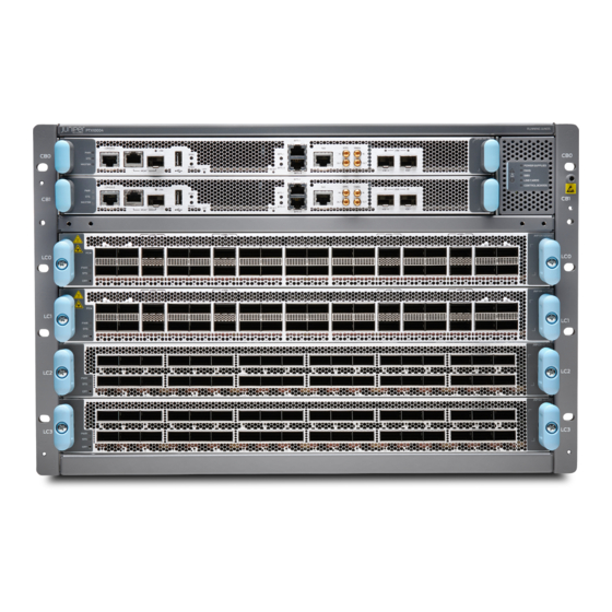
PTX10008 router. Chassis Description The PTX10004 router is 7-U tall. You can fix up to six PTX10004 routers in a standard 42-U rack with adequate cooling and power. All key PTX10004 router components are field-replaceable units (FRUs). - Page 21 Figure 1: PTX10004 Chassis Front Figure 2: PTX10004 Chassis Rear...
-
Page 22: Switch Fabric
Switch Fabric Switch Interface Boards (SIBs) create the switch fabric for the PTX10004. Each SIB has a set of connectors to mate the line cards and the Routing and Control Board (RCB) to the switch fabric. See Figure 4 on page 23 for an example of the JNP10004-SF3. -
Page 23: Routing And Control Board
Figure 4: JNP10004-SF 3 SIB Routing and Control Board The Routing and Control Board (RCB) contains a Routing Engine and is responsible for system management and system control in the PTX10004. See “PTX10004 Routing and Control Board Components and Descriptions” on page 62. -
Page 24: Line Cards
“PTX10004 Components and Configurations” on page Line Cards The PTX10004 has four horizontal line-card slots. The line cards combine a Packet Forwarding Engine and Ethernet interfaces enclosed in a single assembly. The PTX10004 line-card architecture is based on a number of identical, independent Packet Forwarding Engine slices. Line cards are FRUs that can be installed in the line-card slots labeled 0 through 3 (top to bottom) on the front of the chassis. -
Page 25: Cooling System
Cooling System The cooling system in a PTX10004 consists of two fan trays (see Figure 7 on page 25) and two fan tray controllers (see Figure 8 on page 25). The JNP10004-FAN2 fan tray contains an array of six fans and operates as a single hot-removable and hot-insertable field-replaceable unit (FRU). -
Page 26: Power Supplies
Power Supplies The PTX10004 router support AC, DC, high-voltage alternating current (HVAC), and high-voltage direct current (HVDC), by offering the following power supplies: JNP10K-PWR-AC2 JNP10K-PWR-DC2 Power supplies for the PTX10004 are load-sharing hot-removable and hot-insertable FRUs. The router operates with three power supplies. Each power supply has an internal fan for cooling. You can install the power supplies in any slot. -
Page 27: Software
Software The Juniper Networks PTX10004 packet transport router runs on the Junos OS Evolved operating system, which provides Layer 3 routing services. Junos OS Evolved is the next-generation Junos OS. It has the same CLI, the same features, and, in some cases, even the same processes as in the previous versions of Junos OS. -
Page 28: Ptx10004 Components And Configurations
PTX10004 Components and Configurations IN THIS SECTION PTX10004 Configurations | 28 PTX10004 Configurations Table 5 on page 28 lists the hardware configurations for a PTX10004 modular chassis and the components included in each configuration. Table 5: PTX10004 Hardware Configurations Router Configuration Configuration Components... - Page 29 Table 5: PTX10004 Hardware Configurations (continued) Router Configuration Configuration Components Redundant AC configuration Chassis (JNP10004-CHAS) Two RCBs (JNP10K-RE1-E or JNP10K-RE1-E128) PTX10004-PREM2 Two fan tray controllers (JNP10004-FTC2) Two fan trays (JNP10004-FAN2) Three AC power supplies (JNP10K-PWR-AC2) Four SIBs (JNP10004-SF3) Two SIB covers (JNP10004-SF-BLNK2))
-
Page 30: Ptx10004 Component Redundancy
PTX10004 Switch Interface Board Description | 68 PTX10004 Component Redundancy The PTX10004 router is designed so that no single point of failure can cause the entire system to fail. The following major hardware components in the redundant configuration provide redundancy: Routing and Control Board (RCB)—The RCB consolidates the Routing Engine function with the control... -
Page 31: Ptx10004 Hardware And Cli Terminology Mapping
You can populate and run the 14.4-Tbps line cards but a power alarm is raised, which is expected behavior. The PTX10004 router also supports power source redundancy. Four sets of lugs are provided for the JNP10K-PWR-DC2 cables, and two AC power cords are provided for each JNP10K-PWR-AC2 power supply. - Page 32 Table 6: CLI Equivalents of Terms Used in Documentation for PTX10004 Routers (continued) Hardware Item In Item (CLI) Description (CLI) Value (CLI) Documentation Additional Information PIC (n) – Value of n is always 0. – Understanding Interface Naming Conventions PSM (n)
-
Page 33: Ptx10004 Chassis
The PTX10004 modular chassis is a rigid sheet-metal structure that houses the other router components. You can mount up to six PTX10004 routers in a standard 19-in. 4-post rack (42 U) provided the rack can handle the combined weight and there is adequate power and cooling. See... - Page 34 Do not use the handles to lift the chassis, even when the chassis is empty. See “Mount a PTX10004 in a Four-Post Rack Using a Mechanical Lift” on page 129 “Manually Mount a PTX10004 in a Four-Post Rack” on page 132 for instructions on properly moving a loaded chassis.
-
Page 35: Ptx10004 Field-Replaceable Units
Hot-pluggable—You can remove and replace these components without powering off the router, but the routing function is interrupted until you replace the component. Table 8 on page 36 lists the FRUs and their types for the PTX10004 routers. - Page 36 Table 8: FRUs in a PTX10004 Type Power supplies Hot-insertable and hot-removable. Fan trays Hot-insertable and hot-removable. Fan tray controllers Hot-insertable and hot-removable. Routing and Control Boards Redundant configuration: (RCBs) Primary RCB is hot-pluggable. Backup RCB is hot-insertable and hot-removable.
-
Page 37: Ptx10004 Status Panel
The PTX10004 status panel shows the overall status of the chassis. PTX10004 chassis ship with an enhanced power bus to future-proof the chassis for potential power growth. The status panel indicates the chassis status through a set of five bicolor LEDs. It has an Azure blue stripe along the left side of the LEDs. - Page 38 Table 9: Status Panel LEDs on a PTX10004 Name Color State Description ! Minor alarm (Triangle Yellow No minor alarms are active. warning symbol) On steadily A minor alarm is active. Alarm (Bell symbol) Yellow No minor alarms are active.
-
Page 39: Ptx10004 Optional Equipment
The installed RCBs are offline. PTX10004 Optional Equipment The PTX10004 routers offers a cable management system (JLC-CBL-MGMT-KIT) and an electrostatic discharge (ESD) front door with an air filter (JNP10004-FPNL1) a as optional equipment. An ESD front door (JNP10004-FRNT-PNL) without an air filter comes standard with each configuration. -
Page 40: Ptx10004 Cooling System
Fan Tray Controller | 42 Airflow Direction in the PTX10004 | 46 The cooling system in a PTX10004 chassis consists of dual fan trays (JNP10004-FAN2) with matching dual fan tray controllers (JNP10004-FTC2). Each fan tray requires a companion fan tray controller to be installed and operational to be hot-insertable and hot-removable. - Page 41 Figure 13: JNP10004-FAN2 Fan Tray Figure 14: Installed Fan Trays on a PTX10004 Power supplies Fan trays — — Table 10 on page 41 for the physical specifications of the fan trays. Table 10: Fan Tray Specifications Specification JNP10004-FAN2 Corresponding fan tray controller model...
-
Page 42: Fan Tray Controller
The internal fan control board in each fan tray contains the LEDs for the associated fan tray controllers and the LEDs for the three SIBs directly behind the fan tray. Fan Tray Controller The PTX10004 supports two fan tray controllers to provide the control logic and power to hot-insert and hot-remove a fan tray:... - Page 43 JNP10004-FTC2—Supports model JNP10004-FAN2; see Figure 15 on page Figure 15: Fan Tray Controller JNP10004-FTC2 WARNING: Do not mix the fan tray controller models. Use only the supported fan tray model for each fan tray controller. See Table 11 on page Table 11: Fan Tray Controller Specifications Specification JNP10004-FTC2...
- Page 44 user@system> show chassis fan Item Status % RPM Measurement Fan Tray 0 Fan 0 6300 RPM Fan Tray 0 Fan 1 7500 RPM Fan Tray 0 Fan 2 6450 RPM Fan Tray 0 Fan 3 7350 RPM Fan Tray 0 Fan 4 6300 RPM Fan Tray 0 Fan 5 7500 RPM...
- Page 45 Fan Tray 0 Outlet Temp Sensor 32 degrees C / 89 degrees F Fan Tray 1 Inlet Temp Sensor 27 degrees C / 80 degrees F Fan Tray 1 Outlet Temp Sensor 32 degrees C / 89 degrees F FPC 3 BT-0 HBM-0 Temperature 53 degrees C / 127 degrees F FPC 3 BT-0 HBM-1 Temperature 54 degrees C / 129 degrees F...
-
Page 46: Airflow Direction In The Ptx10004
Routing and Control Boards (RCBs) and line cards, through the Switch Interface Boards (SIBs), and exits from the fan trays and the power supplies. See Figure 16 on page Figure 16: Airflow Through a PTX10004 Side view Fan tray controllers... -
Page 47: Ptx10004 Fan Tray Leds And Fan Tray Controller Leds
You can check the status of fans by viewing the LEDs on each fan tray. See “PTX10004 Fan Tray LEDs and Fan Tray Controller LEDs” on page You cannot replace a single fan. If one or more fans fail, you must replace the entire fan tray. - Page 48 Figure 17: Fan Tray JNP10004-FAN2 LEDs FAN FTC SIB STATUS Fan status LED SIB status LEDs (SIB 0 through SIB 2 for the left fan — — tray and SIB 3 through SIB 5 for the right fan tray) Fan tray controller status LED —...
- Page 49 Table 12: Fan Tray LEDs on a PTX10004 Name Color State Description FAN (fan status) Green On steadily All fans are operating normally. The system has verified that the fan tray is engaged, that the airflow is in the correct direction, and that all fans are operating correctly.
- Page 50 Table 12: Fan Tray LEDs on a PTX10004 (continued) Name Color State Description SIB Status (SIB 0 status) Green On steadily The left-most SIB in the chassis is online. Amber Blinking An error has been detected in SIB 0. Replace the SIB as soon as possible. The SIB is located behind the left fan tray and is the left-most SIB in the chassis.
- Page 51 Table 12: Fan Tray LEDs on a PTX10004 (continued) Name Color State Description SIB Status (SIB 2 status) Green On steadily The right-most SIB behind the left fan tray is online. Amber Blinking An error has been detected in SIB 2.
-
Page 52: Fan Tray Controller Leds
Table 12: Fan Tray LEDs on a PTX10004 (continued) Name Color State Description SIB Status (SIB 4 status) Green On steadily The center SIB behind the right fan tray is online. Amber Blinking An error has been detected in SIB 4. - Page 53 Figure 18: Fan Tray Controller LEDs on a PTX10004 Fan tray controller power Fan tray controller status — — Table 13 on page 53 describes the functions of the fan tray controller LEDs. Table 13: Fan Tray Controller LEDs on a PTX10004...
-
Page 54: Ptx10004 Power System
JNP10K-PWR-DC2 Power Supply LEDs | 60 You can install up to three power supplies in a PTX10004 router in the slots labeled PSU0 through PSU2 (top to bottom) located in the rear of the chassis. The JNP10K-PWR-AC2 is designed for AC, high-voltage alternating current (HVAC) and high-voltage direct current (HVDC) environments and can be set for single or dual feeds and high or low output settings. - Page 55 The JNP10K-PWR-AC2 power supply has internal fans that contribute to chassis cooling. Consequently, all three power supplies must be present in a running chassis to have the adequate airflow. While all power supplies are required to be present in the chassis, they do not necessarily need to be all connected to power.
-
Page 56: Jnp10K-Pwr-Dc2 Power Supply
CAUTION: Use a 2-pole circuit breaker rated at 25 A in the building installation and the system, or as per local electrical code. Table 14: DIP Switch Settings for JNP10K-PWR-AC2 Power Supplies H/L (High Input 30 A/ INP0 (Switch 1) INP1 (Switch 2) Low Input 20 A) Output Power... - Page 57 Table 15: DIP Switch Settings for JNP10K-PWR-DC2 Power Supplies INP0 INP1 (High Input 80 A/ (Switch 1) (Switch 2) Low Input 60 A) Output Power On (80 A) 5500 W Off (60 A) 4400 W On (80 A) 2750 W On (80 A) 2750 W Off (60 A)
-
Page 58: Jnp10K-Pwr-Ac2 Power Supply Leds
CAUTION: Before you begin installing the router, ensure that a licensed electrician has attached an appropriate grounding lug to the grounding cable that you supply. Using a grounding cable with an incorrectly attached lug can damage the router. JNP10K-PWR-AC2 Power Supply LEDs The JNP10K-PWR-AC2 power supply has four LEDs on its faceplate: !, OK, 2, and 1. - Page 59 Command INP1 INP0 INP2 INP1 Table 17 on page 59 describes the LEDs on a JNP10K-PWR-AC2 power supply. Table 17: JNP10K-PWR-AC2 LEDs on a PTX10004 Color State Description 1 or (INPO in CLI output) Yellow Blinking The input voltage is present, but a fault is detected.
-
Page 60: Jnp10K-Pwr-Dc2 Power Supply Leds
Table 17: JNP10K-PWR-AC2 LEDs on a PTX10004 (continued) Color State Description OK (Power OK) Green Solid The power supply is functioning properly. Yellow Blinking The power supply output has detected a fault. ! (Fault) Solid The power supply has failed and must be replaced. - Page 61 If the ! LED is blinking, add a power supply to balance the power demand and supply. RELATED DOCUMENTATION PTX10004 Power Planning | 89 Install and Remove PTX10004 Power System Components | 176...
-
Page 62: Ptx10004 Routing And Control Board Components And Descriptions
Routing and Control Board Components | 63 Routing and Control Board Physical Specifications | 64 The PTX10004 Routing and Control Board (RCB) is responsible for system management (see Figure 23 on page 63). The chassis can run with one or two RCBs. We ship the base configuration with one RCB, and you can expand the configuration with a second RCB for a fully redundant system. -
Page 63: Routing And Control Board Functions
JNP10K-RE1-E (64 GB, standard) JNP10K-RE1-E128 (128 GB, spare) Figure 23: JNP10K-RE1-E and JNP10K-RE1-E128 Routing and Control Board Functions The RCB integrates the control plane and Routing Engine functions into a single management unit. Each RCB provides all the functions needed to manage the operation of the modular chassis: System control functions such as environmental monitoring Routing Layer 2 and Layer 3 protocols Communication to all components such as line cards, Switch Interface Boards (SIBs), and power and... -
Page 64: Routing And Control Board Physical Specifications
Figure 24: Routing and Control Board Faceplate (JNP10K-RE1-E and JNP10K-RE1-128E) Handle Reset button — — BITS-1 clock port OFF LED — — GPS clock ports (1PPS and 10MHz) USB port — — XGE-0 and XGE-1 not used (reserved ports) Management (MGMT) ports —... -
Page 65: Ptx10004 Routing And Control Board Leds
PTX10004 Routing and Control Board LEDs IN THIS SECTION Routing and Control Board Status Panel LEDs | 65 PTX10004 Management Port LEDs | 66 Clock LEDs | 67 The JNP10K-RE1-E Routing and Control Board (RCB) has various types of LED indicators (see Figure 25 on page 65). -
Page 66: Ptx10004 Management Port Leds
PTX10004 Management Port LEDs The two management ports on the RCB of a PTX10004 have LEDs that indicate link status and link activity. These two ports, located on the RCB panel between the clocking connections and the USB port, are both labeled MGMT. -
Page 67: Clock Leds
Table 21 on page 67 describes the RJ-45 management port LEDs, and Table 22 on page 67 describes the SFP status LED. Table 21: RJ-45 Management Port LEDs on a PTX10004 Routing and Control Board Color State Description Port speed Unlit The port speed is 10 MB. -
Page 68: Ptx10004 Switch Fabric
The SIBs make up the PTX10004 switching plane that supports the 14.4-Tbps line card and operates in Junos OS Evolved systems. Each SIB has four connectors that correspond to a matching connector on one of the four line cards;... - Page 69 You must remove one of the fan trays to view the SIBs. For instructions on removing the fan trays, see “Remove a PTX10004 Fan Tray” on page 169. The SIBs are numbered SIB0 to SIB5 from left to right. See...
-
Page 70: Ptx10004 Line Card Components And Descriptions
Fan tray controllers SIBs — — SEE ALSO Install a PTX10004 Switch Interface Board | 198 Remove a PTX10004 Switch Interface Board | 203 PTX10004 Line Card Components and Descriptions IN THIS SECTION PTX10K-LC1201-36CD Line Card | 71 PTX10K-LC1201-36CD Network Ports | 73... -
Page 71: Ptx10K-Lc1201-36Cd Line Card
The line cards in PTX10004 routers combine a Packet Forwarding Engine and Ethernet interfaces in a single assembly. Line cards are field-replaceable units (FRUs) that can be installed in the line-card slots on the front of the router chassis. The JNP10004-SF line cards are hot-insertable and hot-removable—you can remove and replace them without powering off the router or disrupting router functions. - Page 72 Table 25: PTX10K-LC1201-36CD Summary (continued) Hardware features Line-rate throughput of up to 14.4 Tbps on PTX10008 and PTX10004 routers Juniper custom silicon ASICs for increased scaling of bandwidth, subscribers, and services You can channelize the ports using breakout cables to speeds of 200-Gbps, 100-Gbps, 50-Gbps, 25-Gbps,...
-
Page 73: Ptx10K-Lc1201-36Cd Network Ports
Table 25: PTX10K-LC1201-36CD Summary (continued) Serial Number The serial number ID label for a line card is located on the connector end of the card. See Figure 31 on page Location Figure 31: Line Card Serial Number Location Serial number ID label PTX10K-LC1201-36CD Network Ports The QSFP56-DD ports support: 400GbE transceivers (QSFP56-DD) -
Page 74: Ptx10K-Lc1202-36Mr Line Card
PTX10K-LC1202-36MR Line Card PTX10K-LC1202-36MR is a 36-port line card, which provides a line rate throughput of 4.8 Tbps. The line card has thirty-two QSFP28 ports, each capable of supporting a maximum speed of 100 Gbps, and four QSFP56-DD ports, each capable of supporting a maximum speed of 400 Gbps. JNP10K-LC1202 Status LED, power LED, and offline button. - Page 75 (ports 0 through 3, 5 through 9, 11 through 23, 25 through 29, and 31 through 35) are 100GbE (QSFP28) ports. Juniper Networks custom silicon ASICs for increased scaling for bandwidth, subscribers, and services. By using breakout cables, you can channelize: Each 400GbE port to two or four 100GbE ports, four or eight 25GbE ports, or four 10GbE ports.
- Page 76 Red, on steadily: The line card has a fault condition. Cables and connectors Use the Hardware Compatibility Tool to find information about the pluggable transceivers supported on your Juniper Networks device. The list of supported transceivers for the PTX Series is located at PTX Series Supported Transceivers.
-
Page 77: Ptx10K-Lc1202-36Mr Network Ports
PTX10K-LC1202-36MR Network Ports The QSFP56-DD ports (ports 4, 10, 24, and 30) on the PTX10K-LC1202-36MR line card support: 1x400GbE transceivers (QSFP56-DD) 4x100GbE transceivers (QSFP56-DD) 2x100GbE transceivers (QSFP28-DD) 8x25GbE transceivers (QSFP28-DD) 1x100GbE transceivers (QSFP28) 4x25GbE transceivers (QSFP28) 4x10GbE transceivers (QSFP+) The QSFP28 ports (ports 0 through 3, 5 through 9, 11 through 23, 25 through 29, and 31 through 35) on the PTX10K-LC1202-36MR line card support: 1x100GbE transceivers (QSFP28) 4x25GbE transceivers (QSFP28) -
Page 78: Ptx10K-Lc1202-36Mr Port Numbering
Figure 33 on page 78 shows an example of the port numbering for the PTX10K-LC1202-36MR line card used in the slot 3 of the PTX10004 line card. PTX10004 Cable Management System You can use the PTX10004 cable management system (see... - Page 79 Figure 34: PTX10004 Cable Management System The cable management system comprises a set of handle extensions and a tray that snaps to the extensions (see Figure 35 on page 79) for an individual line card. You can use the handle extensions with or without the cable tray.
- Page 80 Figure 36: Two Cable Management Systems Installed on a PTX10004 SEE ALSO Install the PTX10004 Cable Management System | 215...
-
Page 81: Site Planning, Preparation, And Specifications
C HAPTER Site Planning, Preparation, and Specifications PTX10004 Site Preparation Overview | 82 PTX10004 Power Planning | 89 PTX10004 Transceiver and Cable Specifications | 104 PTX10004 Console and Management Cable Specifications and Pinouts | 110... -
Page 82: Ptx10004 Site Preparation Overview
PTX10004 Site Electrical Wiring Guidelines | 85 PTX10004 Rack Requirements | 86 PTX10004 Clearance Requirements for Airflow and Hardware Maintenance | 88 The following sections describe the guidelines, the specifications, and the requirements to install a PTX10004 router. PTX10004 Site Preparation Checklist... -
Page 83: Ptx10004 Environmental Requirements And Specifications
□ Plan the cable routing and management. PTX10004 Environmental Requirements and Specifications The PTX10004 router must be installed in a four-post rack. It must be housed in a dry, clean, well-ventilated, and temperature-controlled environment. Follow these environmental guidelines: Ensure that the site is as dust-free as possible, because dust can clog air intake vents and filters, reducing the efficiency of the router cooling system. -
Page 84: Ptx10004 General Site Guidelines
Designed to comply with Zone 4 earthquake requirements according to NEBS GR-63-CORE, Issue 3. NOTE: Install PTX10004 routers only in restricted-access areas, such as dedicated equipment rooms and equipment closets, in accordance with Articles 110-16, 110-17, and 110-18 of the National Electrical Code, ANSI/NFPA 70. -
Page 85: Ptx10004 Site Electrical Wiring Guidelines
Install the device in a secure area so that only authorized personnel can access the device. SEE ALSO Prevention of Electrostatic Discharge Damage | 298 PTX10004 Site Electrical Wiring Guidelines Table 28 on page 85 describes the factors you must consider while you plan the electrical wiring at your site. -
Page 86: Ptx10004 Rack Requirements
OSP cabling. The addition of primary protectors is not sufficient protection to connect these interfaces metallically to OSP wiring. PTX10004 Rack Requirements The PTX10004 router chassis is designed to be installed in four-post racks. Rack requirements consist of: Rack type... - Page 87 Associated Equipment (document number EIA-310–D) published by the Electronics Industries Association (EIA). You can stack a maximum o six PTX10004 routers in a four-post rack if: The rack is 42 U or greater. The rack meets the strength requirements to support the weight and seismic requirements.
-
Page 88: Ptx10004 Clearance Requirements For Airflow And Hardware Maintenance
Leave at least 30 in. (76.2 cm) in front of the chassis and at least 24 in. (61 cm) behind the PTX10004 for service personnel to remove and install hardware components. To be NEBS GR-63 compliant, allow... -
Page 89: Ptx10004 Power Planning
PTX10004 Power Cable Specifications | 96 JNP10K-PWR-DC2 Power Specifications | 102 PTX10004 Grounding Cable and Lug Specifications | 103 Use the information in this topic to calculate the power consumption for the PTX10004 and plan your configuration’s power requirements. Power Requirements for PTX10004 Components... -
Page 90: Calculate Power Requirements For A Ptx10004 Router
(thirty-two 100GbE ports and four 400GbE ports). Calculate Power Requirements for a PTX10004 Router Use the information in this topic to calculate power requirements of your PTX10004 configuration and the number of power supplies required for different PTX10004 router configurations. CAUTION: To ensure adequate power and to avoid raising a power alarm, we recommend that you maintain n +1 power supplies in your router at all times. -
Page 91: How To Calculate The Power Consumption Of Your Ptx10004 Configuration
This topic describes these tasks: How to Calculate the Power Consumption of Your PTX10004 Configuration | 91 How to Calculate the Number of Power Supplies Required for Your PTX10004 Configuration | 92 How to Calculate the Power Consumption of Your PTX10004 Configuration Use the following procedure to determine the maximum power you need to supply to the router. -
Page 92: How To Calculate The Number Of Power Supplies Required For Your Ptx10004 Configuration
How to Calculate the Number of Power Supplies Required for Your PTX10004 Configuration The minimum power configuration for PTX10004 routers is three power supplies. However, using the calculated minimum power configuration doesn’t prevent the system from raising a power alarm. To ensure you don’t log power alarms with a fully loaded chassis, you must configure your router for dual feed and... - Page 93 A) or low power (20 A) input mode. Table 33 on page 93 Table 34 on page 93 showsthe power available for the installed power supplies. Table 33: Total Power Available Power Supply Module Models With Two Power Supplies With Three Power Supplies JNP10K-PWR-AC2 dual feed, high 11,000 W 16,500 W...
- Page 94 Table 34: Power Voltages Settings for JNP10K-PWR-AC2 and JNP10K-PWR-DC2 Power Supplies (continued) H/L (High Input/ INP0 (Switch 1) INP1 (Switch 2) Low Input Switch 3) Output Power Off (Low 20 A) 2700 W Off (Low20 A) 2700 W JNP10K-PWR-DC2 On (High 80 A) 5500 W Off (Low 60 A) 4400 W...
-
Page 95: Jnp10K-Pwr-Ac2 Power Specifications
In the previous examples, we calculated that a PTX10004 AC system requires 8325 W with three PTX10K-LC1201-36CD line cards. In this example, we calculate the total power available for JNP10K-PWR-AC2 power supplies set for dual feed and low power in a PREM2 configuration: = (8325 W) / (3000 W) dual input, low power = 2.78... -
Page 96: Ptx10004 Power Cable Specifications
210-52 and Canadian Electrical Code (CEC) Section 4-010(3). The cords shipped with the router to North America and Canada are in compliance. The PTX10004 AC, high-voltage alternating current (HVAC), and high-voltage direct current (HVDC) power supplies have specific cord requirements. Use the following sections to determine the cable requirements... -
Page 97: Jnp10K-Pwr-Ac2 Power Cable Specifications
JNP10K-PWR-AC2 Power Cable Specifications The JNP10K-PWR-AC2 power supply operates in two modes: 20-A input with 3000-W output; see Table 37 on page 98 for a list of appropriate cables. 30-A input with 5500-W output; see “JNP10K-PWR-AC2 Power Cable Specifications for 30-A Input” on page 100 for a list of appropriate cables and connectors for 30-A input. - Page 98 Table 37: JNP10K-PWR-AC2 Power Cable Specifications for 20-A Input Spare Juniper Locale Cord Set Rating Plug Standard Model Number Graphic Argentina 16 A, 250 VAC IRAM 2073 Type CBL-JNP-SG4-AR RA/3 Australia and New 15 A, 250 VAC AS/NZS 3112 CBL-JNP-SG4-AU...
- Page 99 Table 37: JNP10K-PWR-AC2 Power Cable Specifications for 20-A Input (continued) Spare Juniper Locale Cord Set Rating Plug Standard Model Number Graphic India 16 A, 250 VAC SANS 164/1 CBL-JNP-SG4-SA Israel 16 A, RA, 250 VAC SI 32/1971 Type CBL-JNP-SG4-IL IL/3C...
-
Page 100: Jnp10K-Pwr-Ac2 Power Cable Specifications For 30-A Input
JNP10K-PWR-AC2 orders. An example of the right-angle cable and connector is shown in Figure 40 on page 102. For connection to AC systems, Juniper provides a cable with either a NEMA 30-A connector (Figure 38 on page 100) or an IEC 330P6W connector (Figure 39 on page 100). - Page 101 Table 38: 30-A Cabling Options Cord Set Plug Spare Juniper Model Option Locale Rating Standards Connector Number HVAC/HVDC 30 A UL 950 and IEC Anderson/straight to CBL-PWR2-BARE power cord 400 VAC 60950 bare wire 30 A UL 950 and IEC...
-
Page 102: Jnp10K-Pwr-Dc2 Power Specifications
Green wire - Ground — JNP10K-PWR-DC2 Power Specifications Table 39 on page 102 lists the power specifications for the high-voltage direct current (HVDC) power supply used in PTX10004 routers. Table 39: Power Specifications for the JNP10K-PWR-DC2 Power Supply Item Specifications DC input voltage Minimum operating voltage: –40 VDC... -
Page 103: Ptx10004 Grounding Cable And Lug Specifications
You must install the PTX10004 in a restricted-access location and ensure that the chassis is always properly grounded. The PTX10004 has a two-hole protective grounding terminal provided on the chassis. Under all circumstances, use this grounding connection to ground the chassis. -
Page 104: Ptx10004 Transceiver And Cable Specifications
90° C or as permitted by local electrical code. The grounding cable that you provide for a PTX10004 must be the same size as, or heavier than, the input wire of each power supply. Minimum recommendations are 6 AWG (13.3 mm²) stranded copper wire, Class B;... -
Page 105: Ptx10004 Optical Transceiver And Cable Support
The Hardware Compatibility Tool enables you to search by product, displaying all the transceivers supported on that device, or category, by interface speed or type. The list of supported transceivers for the PTX10004 is located at https://pathfinder.juniper.net/hct/product/#prd=PTX10004. -
Page 106: Ptx10004 Fiber-Optic Cable Signal Loss, Attenuation, And Dispersion
Attenuation and Dispersion in Fiber-Optic Cables | 107 To determine the power budget and power margin needed for fiber-optic connections, you need to understand how signal loss, attenuation, and dispersion affect transmission. The PTX10004 router uses various types of network cables, including multimode and single-mode fiber-optic cables. -
Page 107: Attenuation And Dispersion In Fiber-Optic Cables
index material in close contact with a core material of higher refractive index), higher-order mode loss occurs. Together, these factors reduce the transmission distance of multimode fiber compared to that of single-mode fiber. Single-mode fiber is so small in diameter that rays of light reflect internally through one layer only. Interfaces with single-mode optics use lasers as light sources. -
Page 108: Calculate The Fiber-Optic Cable Power Budget For A Ptx Series Router
Calculate the Fiber-Optic Cable Power Budget for a PTX Series Router Calculate the link's power budget when planning fiber-optic cable layout and distances to ensure that fiber-optic connections have sufficient power for correct operation. The power budget is the maximum amount of power the link can transmit. - Page 109 Before you begin to calculate the power margin, calculate the power budget. To calculate the worst-case estimate for the power margin (P ) for the link: 1. Determine the maximum value for LL by adding estimated values for applicable link-loss factors; for example, use the sample values for various factors as provided in Table 42 on page 109 (here, the link...
-
Page 110: Ptx10004 Console And Management Cable Specifications And Pinouts
RJ-45 connector to connect to a console management device. The default baud rate for the console port is 9600 baud. Table 43 on page 111 provides the pinout information for the RJ-45 console connector. An RJ-45 cable and RJ-45 to DB-9 adapter are supplied with the PTX10004 routers. - Page 111 If your laptop or PC does not have a DB-9 connector pin (plug) and you want to connect your laptop or PC directly to a PTX10004 router, use a combination of the RJ-45 cable and RJ-45 to DB-9 adapter supplied with the device and a USB to DB-9 plug adapter. You must provide the USB to DB-9 plug adapter.
-
Page 112: Usb Port Specifications For The Ptx10004
USB Port Specifications for the PTX10004 The following Juniper Networks USB flash drives have been tested and are officially supported for the USB port in the PTX10004 routers: RE-USB-1G-S—1-gigabyte (GB) USB flash drive RE-USB-2G-S—2-GB USB flash drive RE-USB-4G-S—4-GB USB flash drive... - Page 113 Table 44: RJ-45 Management Port Connector Pinouts for the PTX10004 Signal Description TRP1+ Transmit/receive data pair 1 TRP1– TRP2+ Transmit/receive data pair 2 TRP3+ Transmit/receive data pair 3 TRP3– TRP2– Transmit/receive data pair 2 TRP4+ Transmit/receive data pair 4 TRP4–...
-
Page 114: Initial Installation And Configuration
Initial Installation and Configuration PTX10004 Installation Overview | 115 Unpack the PTX10004 Router | 116 Install the Mounting Hardware for a PTX10004 | 126 Install the PTX10004 into a Rack | 129 Install the Front Door on a PTX10004 | 137... -
Page 115: Ptx10004 Installation Overview
The router chassis ships in a cardboard box that has a two-layer wooden pallet base. The router chassis is bolted to the pallet base. You can install a PTX10004 router in a standard 19-in. (483-mm) equipment rack by using the supplied rack mount kit and the flange that is attached to the chassis. -
Page 116: Unpack The Ptx10004 Router
IN THIS SECTION Unpack the PTX10004 Shipping Pallet | 116 Unpack Line Cards, Routing Control Boards, and Switch Interface Boards for the PTX10004 | 118 Compare the PTX10004 Order to the Packing List | 121 Register Products—Mandatory to Validate SLAs | 125 To unpack the PTX10004 router and its components, read the following sections. - Page 117 See Figure 41 on page 117. Figure 41: Shipping Crate and Accessory Box Cardboard shipping box PTX10004 chassis — — Cardboard accessory box Wood pallet —...
-
Page 118: Unpack Line Cards, Routing Control Boards, And Switch Interface Boards For The Ptx10004
9. Unpack the accessory box and lay out the contents so that they are ready for use. 10. Verify that your order includes all appropriate parts. See “Compare the PTX10004 Order to the Packing List” on page 121 “PTX10004 Components and Configurations” on page 28 for information about base configurations and redundant configurations. - Page 119 161 How to Handle and Store PTX10004 SIBs on page 196 How to Handle and Store PTX10004 Line Cards on page 207 To unpack an RCB, a SIB, or a line card: 1. Move the shipping carton to a staging area as close to the installation site as possible.
- Page 120 Figure 43: Unpack a Line Card Foam packing material Paper packaging and antistatic bag — — SEE ALSO Install a PTX10004 Line Card | 209 Install a PTX10004 Switch Interface Board | 198 Install a PTX10004 Routing and Control Board | 162...
-
Page 121: Compare The Ptx10004 Order To The Packing List
The packing list specifies the part number and description of each part in your order. If any part on the packing list is missing, contact your customer service representative, or contact Juniper Networks Customer Care from within the U.S. or Canada by telephone at 1-888-314-5822. For international-dial or direct-dial options in countries without toll-free numbers, see https://www.juniper.net/support/requesting-support.html. - Page 122 Table 45: BASE3 Configuration Order (continued) Component PTX10004 Quantity RCBs, JNP10K-RE1-E Cover panel, in the RCB slot Fan tray controllers Fan trays Power supplies SIBs Cover in a SIB position Covers in the line-card positions Dust covers for RCB ports...
- Page 123 Table 46: PREM2 Configuration Order (continued) Component PTX10004 Quantity Power supplies: JNP10K-PWR-AC2 JNP10K-PWR-DC2 Switch Interface Boards Covers in the line-card positions Accessory kit (see Table 48 on page 124) Rack mount kit (see Table 49 on page 124) Front panel kit (see...
- Page 124 Premium = 24 Base = 12 Antistatic bags 4. Compare the contents of the rack mount kit with Table 49 on page 124. Table 49: PTX10004 Rack Mount Kit Component Quantity Phillips flat-head screws, 8-32 x .375 in. Rear rails...
-
Page 125: Register Products-Mandatory To Validate Slas
Front door with air filter Line-card handle extensions Cable tray Cable seals Register Products—Mandatory to Validate SLAs Register all new Juniper Networks hardware products and changes to an existing installed product using the Juniper Networks website to activate your hardware replacement service-level agreements (SLAs). -
Page 126: Install The Mounting Hardware For A Ptx10004
Install the Mounting Hardware for a PTX10004 You can install a PTX10004 router in a four-post closed frame rack or a four-post open frame rack. Install the mounting hardware on the rack before you install the router. To mount the chassis on a four-post rack, you must first install the mounting hardware in the rack. The PTX10004 router comes with a four-piece set of brackets that supports the chassis in the rack. - Page 127 2. Decide where to place the chassis in the rack. The best practice is to mount the router in the lowest possible location when the rack is empty. See “PTX10004 Rack Requirements” on page 3. Align the mounting tray so that its front screw holes line up with the holes in the rack. Use six mounting screws appropriate for your rack to attach the mounting tray to the rack.
- Page 128 Figure 45: Attach the Rear Mounting Rails 5. Ensure thatthe holes in the mounting rail overlap with the holes in the mounting tray. Attach the left base and rear brackets (see Figure 46 on page 128): a. Insert six of the flat-head screws provided with the mounting brackets into the overlapping bracket holes on each side of the mounting tray.
-
Page 129: Install The Ptx10004 Into A Rack
Manually Mount a PTX10004 in a Four-Post Rack | 132 Install the Safety Restraint | 136 You can install a PTX10004 router into a four-post rack by using a mechanical lift, or you can install it manually. The following sections describe both procedures. - Page 130 “PTX10004 Site Preparation Checklist” on page Be sure the site has adequate clearance for both airflow and hardware maintenance as described in “PTX10004 Clearance Requirements for Airflow and Hardware Maintenance” on page Unpack the router as described in “Compare the PTX10004 Order to the Packing List” on page 121.
- Page 131 Figure 47: Load the PTX10004 into a Mechanical Lift 3. Using the lift, align the router in front of the rack, centering it in front of the base brackets. 4. Lift the chassis approximately 0.75 in. (1.9 cm) above the surface of the base brackets. Align the chassis as close as possible to the base brackets.
-
Page 132: Manually Mount A Ptx10004 In A Four-Post Rack
1. Prepare the site for installation as described in “PTX10004 Site Preparation Checklist” on page 2. Ensure the site has adequate clearance for both airflow and hardware maintenance as described in “PTX10004 Clearance Requirements for Airflow and Hardware Maintenance” on page... - Page 133 116. 4. Remove all components except the two fan tray controllers from the chassis. See: Remove a PTX10004 Routing and Control Board on page 164 Remove a PTX10004 Switch Interface Board on page 203 Remove a PTX10004 Fan Tray on page 169...
- Page 134 Do not twist your body as you lift. Balance the load evenly and be sure that your footing is firm. Figure 49: Lift the PTX10004 Without Using a Mechanical Lift 4. Carefully slide the router onto the base and rear mounting brackets until the chassis flanges contact the rack rails.
- Page 135 Install a PTX10004 Switch Interface Board on page 198 Install a PTX10004 Fan Tray on page 167 Install a PTX10004 Routing and Control Board on page 162 “Install a JNP10K-PWR-AC2 Power Supply” on page 177 Install a JNP10K-PWR-DC2 Power Supply...
-
Page 136: Install The Safety Restraint
Install the Safety Restraint The safety restraint is a U-shaped bracket that prevents the chassis from any vertical movement in the rack in the event of an earthquake. This restraint is important for sites with seismic activity. Ensure that you have the following parts and tools available to install the safety restraint: Safety restraint (provided in rack mount kit) Six mounting screws appropriate for your rack (not provided) A Phillips (+) screwdriver, number 2 or number 3, depending on the size of your rack-mounting screws... -
Page 137: Install The Front Door On A Ptx10004
Install and Remove a Front Door with Filter | 139 Install the Front Door on a PTX10004 Router The front door (JNP10004-FRNT-PNL) is required on the PTX10004 to protect fiber-optic cabling and to provide additional protection from electromagnetic interference (EMI). The front door can be installed with or without the optional cable management system. - Page 138 1. Wrap and fasten one end of the Electrostatic Discharge (ESD) grounding strap around your bare wrist and connect the other end of the strap to the ESD point on the front of the chassis. See Figure 53 on page 138. Figure 53: ESD Point for PTX10004 Chassis Front LINK 1PPS 10MHz...
-
Page 139: Install And Remove A Front Door With Filter
— — To install a front door with an air filter: 1. Install the cable management system. See“Install the PTX10004 Cable Management System” on page 215. CAUTION: You must have the extended ejector handles of the cable management system installed to remove or install the line cards if you use the front door with... - Page 140 2. Install the cable seals. a. Remove the top right mounting screw next to the Routing and Control Board (RCB) with the Phillips screwdriver. The mounting screws attach the chassis flanges to the four-post rack. b. Line up the top hole of the RCB cable seal over the mounting hole in the flange and align the second hole over the ESD grounding point.
- Page 141 c. Lift the front door and align the captive screws in the door with holes in the chassis flange below the cable seals. Fasten the door to the chassis and rack using your fingers until finger tight. Figure 57: Attach Front Door Using the Captive Screws LINK 1PPS 10MHz...
- Page 142 Figure 58: Air Filter in a PTX10004 Front Door Air filter frame — CAUTION: Juniper recommends installing the air filter to prevent harmful debris from entering the chassis. 2. Hold the air filter with both hands and insert it into the front door until it stops. See Figure 59 on page 143.
- Page 143 Figure 59: Insert the Air Filter into a PTX1004 Front Door Air filter — 3. Move the air filter frame over the front door and turn the knob on the air filter frame clockwise back in place.
- Page 144 1. Turn the knob on both sides of the air filter frame anti-clockwise and move it over the top of the front door. SeeFigure 60 on page 144. Figure 60: Air Filter in a PTX10004 Front Door Air filter frame — 2. Grasp the air filter with both hands and lift the air filter out of the front door. See Figure 60 on page 144.
- Page 145 Figure 61: Lift the Air Filter Out of the PTX10004 Front Door Air filter —...
-
Page 146: Connect The Ptx10004 To Power
Connect DC Power to a PTX10004 | 150 The PTX10004 routers support AC, DC, high-voltage alternating current (HVAC), and high-voltage direct current (HVDC) power supplies. To connect power to a PTX10004 router, read the following procedures. NOTE: Do not mix power supply models in the same chassis in a running environment. -
Page 147: Connect The Ptx10004 Router To Earth Ground
You must install the PTX10004 in a restricted-access location and ensure that the chassis is always properly grounded. The PTX10004 has a two-hole protective grounding terminal provided on the chassis. See Figure 63 on page 149. - Page 148 3. Wrap and fasten one end of the ESD grounding strap around your bare wrist and connect the other end of the strap to one of the ESD points on the chassis. See Figure 62 on page 148. Figure 62: ESD Point for the PTX10004 FAN FTC SIB STATUS FAN FTC...
-
Page 149: Connect Ac Power To A Ptx10004
This sequence can start incrementally with a single power supply, but we do not recommend that you bring up a PTX10004 system with less than three power supplies. Before you begin to connect power to the router, be sure you understand how to prevent ESD damage. -
Page 150: Connect Dc Power To A Ptx10004
The power-on sequence can start incrementally with a single power supply, but it is not recommended that you bring up a PTX10004 system with less than three power supplies. - Page 151 For installations that require a separate grounding conductor to the chassis, use the protective earthing terminal on the rear panel of the PTX10004 to connect to the earth ground. 2. Connect DC power to the JNP10K-PWR-DC or JNP10K-PWR-DC2 power supply and install in the chassis.
-
Page 152: Connect The Ptx10004 To External Devices
Connect a PTX10004 Router to a Management Console | 153 You can manage the PTX10004 router by using the two management ports on the Routing and Control board (RCB) for out-of-band management or through the console port on the RCB. To connect a PTX10004 router to external management devices, read to the following sections. -
Page 153: Connect A Ptx10004 Router To A Management Console
Management PC Connect a PTX10004 Router to a Management Console The PTX10004 router has a console port with an RJ-45 connector. Use the console port to connect the device to a management console or to a console server. Ensure that you have an RJ-45 to DB-9 rollover cable available. An RJ-45 cable with an RJ-45 to DB-9 adapter is provided with the device. -
Page 154: Perform The Initial Configuration For The Ptx10004
Figure 66: Connect the PTX10004 Router to a Management Console Through a Console Server To Console Port Console Server (on device) Figure 67: Connect the PTX10004 Router Directly to a Management Console Laptop CPU To Console Port (on device) RELATED DOCUMENTATION... -
Page 155: Before You Start
You must perform the initial configuration of the PTX10004 through the console port using the CLI or through zero-touch provisioning (ZTP). To use ZTP to provision the device, you must have access to a Dynamic Host Control Protocol (DHCP) server, and a File Transfer Protocol (anonymous FTP), Hypertext Transfer Protocol (HTTP), or Trivial File Transfer Protocol (TFTP) server on which the software image and configuration files are stored. -
Page 156: Establish A Root Password And An Optional Hostname
3. Log in as root. There is no password. If the software booted before you connected to the console port, you might need to press the Enter key for the prompt to appear. Amnesiac <ttyd0> login: root 4. Start the CLI. root@% cli 5. -
Page 157: Configure Optional Routes, Services, And Commit The Configuration
The management ports, em0 or re0:mgmt-0 (MGMT for RJ-45 connections) and em1 (also labeled MGMT for fiber connections), are found on the front of the RCBs of the PTX10004 router. Configure Optional Routes, Services, and Commit the Configuration 1. (Optional) Configure the static routes to remote prefixes with access to the management port. - Page 158 RELATED DOCUMENTATION PTX10004 System Overview | 19 PTX10004 Installation Overview | 115...
-
Page 159: Maintaining Components
Install and Remove PTX10004 Power System Components | 176 Install and Remove PTX10004 Switch Fabric Components | 195 Install and Remove PTX10004 Line Card Components | 207 PTX10004 Transceiver and Fiber Optic Cable Installation and Removal | 219 Remove the PTX10004 Router | 226... -
Page 160: Install And Remove Ptx10004 Routing And Control Boards
Remove a PTX10004 Routing and Control Board | 164 The PTX10004 modular chassis can house one or two Routing and Control Boards (RCBs), depending on the configuration. You can install RCBs in either of the two top slots on the front of the chassis. After the hot insertion, the RCB powers up and comes online. -
Page 161: How To Store A Routing And Control Board
CAUTION: Do not stack RCBs on top of one another or on top of any other component. 5. Place each RCB in an individual antistatic bag or separately on an antistatic mat that is placed on a flat, stable surface. How to Store a Routing and Control Board You must store an RCB either in the chassis or in a spare shipping container, horizontally and sheet-metal side down. -
Page 162: Install A Ptx10004 Routing And Control Board
Install a PTX10004 Routing and Control Board In redundant configurations, a PTX10004 RCB is a hot-removable and hot-insertable field-replaceable unit (FRU). In base configurations, you need to install a second RCB before you remove a failing RCB to prevent the router from shutting down. - Page 163 PWR LED is blinking yellow, there might be insufficient power available. See “PTX10004 Power Planning” on page 89 “Power Requirements for PTX10004 Components” on page 89 to ensure that you have adequate power for the additional unit. Another method to verifyi that the RCB is online is to use the following CLI command: user@host>...
-
Page 164: Remove A Ptx10004 Routing And Control Board
PTX10004 Routing and Control Board LEDs | 65 Remove a PTX10004 Routing and Control Board In redundant configurations, a PTX10004 RCB is a hot-removable and hot-insertable field-replaceable unit (FRU). In base configurations, you need to install a second RCB before removing a failing RCB to prevent the router from shutting down. - Page 165 For example, your primary RCB is re0 and your backup RCB is re1 and you want to remove the backup RCB from the chassis. You would issue the above commands from the console of the primary RCB. On the console of the backup, you would see output similar to the following: Shutdown at Thu Nov 19 09:40:59 2020 {backup} user@host1>...
- Page 166 3. Wrap and fasten one end of the ESD grounding strap around your bare wrist and connect the other end of the strap to one of the ESD points on the chassis (see Figure 71 on page 166). Figure 71: ESD Point on the Front of the PTX10004 Chassis LINK 1PPS 10MHz...
-
Page 167: Install And Remove Ptx10004 Cooling System Components
Ensure that you understand how to prevent ESD damage. See “Prevention of Electrostatic Discharge Damage” on page 298. Ensure that you have the following parts and tools available to install a fan tray in a PTX10004 router: Electrostatic discharge (ESD) grounding strap... - Page 168 1. Wrap and fasten one end of the ESD grounding strap around your bare wrist and connect the other end of the strap to one of the ESD points on the chassis (see Figure 73 on page 168). Figure 73: ESD Point on the Rear of the PTX10004 FAN FTC SIB STATUS FAN FTC...
-
Page 169: Remove A Ptx10004 Fan Tray
1 speed normal Remove a PTX10004 Fan Tray The PTX10004 chassis has two independent, field-replaceable fan trays (JNP10004-FAN2). Each fan tray is a hot-removable and hot-insertable FRU; you can remove and replace a single fan tray while the router is running without turning off power to the router or disrupting routing functions. - Page 170 “Prevention of Electrostatic Discharge Damage” on page 298. Ensure that you have the following parts and tools available to remove a fan tray from a PTX10004: Electrostatic discharge (ESD) grounding strap Replacement fan tray A Phillips (+) screwdriver, number 1 or 2 (optional), for the captive screws Run the fans at 100 percent of max rated speed for 10 minutes before removing fan tray.
- Page 171 1. Wrap and fasten one end of the ESD grounding strap around your bare wrist and connect the other end of the strap to one of the ESD points on the chassis (see Figure 75 on page 171). Figure 75: ESD Point on the Rear of the PTX10004 FAN FTC SIB STATUS FAN FTC...
-
Page 172: Install A Ptx10004 Fan Tray Controller
Figure 76: Remove a PTX10004 Fan Tray 4. Tilt the top of the fan tray forward. 5. Using both hands, lift the fan tray out of the slot and rest it on a flat surface with the handles to the side. - Page 173 “Prevention of Electrostatic Discharge Damage” on page 298. Ensure that you have the following parts and tools available to install a fan tray controller into a PTX10004: Electrostatic discharge (ESD) grounding strap Replacement fan tray controller (JNP10004-FTC2) A Phillips (+) screwdriver, number 1, for the captive screws (optional) To install a fan tray controller: 1.
-
Page 174: Remove A Ptx10004 Fan Tray Controller
Figure 78: Install the PTX10004 Fan Tray Controller 3. Tighten the captive screws for the fan tray controller by using your thumb and forefinger or using a Phillips screwdriver. 4. Reinstall the fan tray. See “Install a PTX10004 Fan Tray” on page 167. - Page 175 Both models of fan controller are removed using the same procedure. 1. Remove the fan tray. See “Remove a PTX10004 Fan Tray” on page 169. 2. Loosen the two captive screws on each side of the fan tray controller with your thumb and forefinger or with a Phillips screwdriver.
-
Page 176: Install And Remove Ptx10004 Power System Components
Figure 80: Remove the JNP10004-FTC2 Fan Tray Controller 4. Place the fan tray controller in an antistatic bag or on an antistatic mat. RELATED DOCUMENTATION PTX10004 Cooling System and Airflow | 40 PTX10004 Field-Replaceable Units | 35 Install and Remove PTX10004 Power System... -
Page 177: Install A Jnp10K-Pwr-Ac2 Power Supply
The PTX10004 routers support AC, DC, high-voltage alternating current (HVAC), and high-voltage direct current (HVDC) power supplies. To install and remove the power supplies in a PTX10004, read the following sections. All power supply models are hot-insertable and hot-removeable field-replaceable units (FRUs). - Page 178 1. Wrap and fasten one end of the ESD grounding strap around your bare wrist and connect the other end of the strap to an ESD point on the chassis. There is an ESD point located next to the protective earthing terminal and below PSU2 on the rear of the PTX10004 (see Figure 81 on page 178).
- Page 179 You can install the power supplies in any slot labeled PSU 0 through PSU 5 (top to bottom) on a PTX10004. 7. Using both hands, place the power supply in the power supply slot on the rear of the system. Slide the power supply straight into the chassis until the power supply is fully seated in the slot.
- Page 180 WARNING: Ensure that the power cords do not block access to router components or drape where people can trip on them. 12. If the AC or DC power source outlets have a power switch, set them to the on (|) position. 13.
-
Page 181: Remove A Jnp10K-Pwr-Ac2 Power Supply
Do not leave the power supply slot empty for a long time while the router is operational. Either replace the power supply promptly or install a cover over the empty slot. To remove a JNP10K-PWR-AC2 power supply from a PTX10004 router:... - Page 182 1. Wrap and fasten one end of the ESD grounding strap around your bare wrist and connect the other end of the strap to an ESD point on the chassis. There is an ESD point located next to the protective earthing terminal and below PSU 2 on the rear of the PTX10004 (see Figure 83 on page 182).
- Page 183 Figure 84: Remove a JNP10K-PWR-AC2 Power Supply from a PTX10004 6. Rotate the captive screw away from the faceplate of the power supply to release the latch. 7. Wear heat protective gloves before you remove the power supply from the chassis.
-
Page 184: Install A Jnp10K-Pwr-Dc2 Power Supply
CAUTION: To meet safety and electromagnetic interference (EMI) requirements and to ensure proper operation, you must connect the PTX10004 routers to earth ground before you connect them to power. For installations that require a separate grounding conductor to the chassis, use the protective earthing terminal on the router chassis to connect to earth ground. - Page 185 75° C or per local electrical code. We recommend that you install heat-shrink tubing insulation around the crimped section of the power cables and lugs. 13/32 in. (10 mm) nut driver or socket wrench Phillips (+) screwdrivers, numbers 1 and 2 Multimeter To install a JNP10K-PWR-DC2 power supply in a PTX10004:...
- Page 186 1. Wrap and fasten one end of the ESD grounding strap around your bare wrist and connect the other end of the strap to an ESD point on the chassis. There is an ESD point located next to the protective earthing terminal and below PSU 5 on the rear of the PTX10004 (see Figure 85 on page 186).
- Page 187 Figure 86: Remove the Plastic Cable Cover on a JNP10K-PWR-DC2 Power Supply RT N -48 V/- 60V RT N -48 V/- 60V 6. Remove the nuts from each DC power input terminal, using the 13/32 in. (10 mm) nut driver or socket wrench to loosen the nuts.
- Page 188 INPUT A1: : RTN –48V/–60V INPUT B1: : RTN –48V/–60V We recommend source redundancy (source A and source B) to all inputs to ensure reliability of the system. If you not have two power sources available, then having two feeds from the same source provides power distribution reliability because there are two independent power distribution from the source to the system.
- Page 189 Figure 88: Connect the DC Power Source Cables to a JNP10K-PWR-DC2 Power Supply RT N -48 V/- 60V RT N -48 V/- 60V 10. Install the plastic cable cover over each set of power cables by using the Phillips (+) screwdriver, number 2, to tighten the screw.
- Page 190 Figure 89: Install a JNP10K-PWR-DC2 in a PTX10004 16. Route INP1 cables to a power source and INP2 to another power source. The JNP10K-PWR-DC2 shares power, so if power dips on one input, the power supply is able to load-balance internally.
- Page 191 Table 54: Set the JNP10K-PWR-DC2 DIP Switches (continued) Switch State Description Enabled for 80-A feed; 2750 W for a single feed, 5500 W for dual feeds. Enabled for 60-A feed; 2200 W for a single feed, 4400 W for dual feeds. Figure 90: Set the Enable Switches for the Power Source DIP switches Power switch, on (|), and standby (O)
-
Page 192: Remove A Jnp10K-Pwr-Dc2 Power Supply
Do not leave the power supply slot empty for a long time while the router is operational. Either replace the power supply promptly or install a cover over the empty slot. To remove a JNP10K-PWR-DC2 power supply from a PTX10004 router:... - Page 193 1. Wrap and fasten one end of the ESD grounding strap around your bare wrist and connect the other end of the strap to an ESD point on the chassis. There is an ESD point located next to the protective earthing terminal and below PSU 5 on the rear of the PTX10004 (see Figure 91 on page 193).
- Page 194 Figure 92: Remove a JNP10K-PWR-DC2 Power Supply on a PTX10004 6. Rotate the captive screw away from the faceplate of the power supply to release the latch. NOTE: Ensure that the ejector is fully open to avoid seeing the chassis. See Figure 93 on page 194.
-
Page 195: Install And Remove Ptx10004 Switch Fabric Components
Remove a PTX10004 Switch Interface Board | 203 Each PTX10004 router contains a minimum of three and a maximum of six Switch Interface Boards (SIBs) that are installed vertically, mid-chassis, between the line cards and the Routing and Control Boards (RCBs) -
Page 196: How To Handle And Store Ptx10004 Sibs
How to Handle and Store PTX10004 SIBs IN THIS SECTION How to Hold a SIB | 197 How to Store a Switch Interface Board | 198 The PTX10004 SIBs have fragile components. To avoid damage to the SIBs, be sure you follow safe handling practices. -
Page 197: How To Hold A Sib
How to Hold a SIB SIBs are installed vertically and should be held vertically until they are clear of the router before rotating them 90 degrees and placing them on an antistatic mat or placing them in an antistatic bag for storage. Figure 94 on page 197. -
Page 198: How To Store A Switch Interface Board
Install a PTX10004 Switch Interface Board A PTX10004 router has up to six SIBs that are located in the middle of the chassis behind the fan trays. SIB 0 through SIB 2 are located behind the left fan tray, and SIB 3 through SIB 5 are located behind the right fan tray. - Page 199 ESD point on the chassis. There is an ESD point located next to the protective earthing terminal and below the bottom power supply on the rear of the PTX10004 (see Figure 95 on page 199).
- Page 200 Figure 96: Remove a SIB Cover on a PTX10004 5. Lift the SIB by the handle with one hand and support the lower edge with the other hand. 6. Hold the SIB vertically and slide the SIB into the open slot until the ejector handles engage and start to close.
- Page 201 Figure 97: Install a PTX10004 Switch Interface Board 8. Tighten the captive screws using your thumb and forefinger or using a Phillips screwdriver until the captive screws are hand-tight. 9. Bring the SIB online using the request chassis sib slot slot number online command.
- Page 202 PFE #3 : Links ok PFE #4 : Links ok PFE #5 : Links ok PFE #6 : Links ok PFE #7 : Links ok PFE #8 : Links ok Asic #0 Fcore #0 (plane 2) Active FPC #3 PFE #0 : Links ok PFE #1 : Links ok...
-
Page 203: Remove A Ptx10004 Switch Interface Board
Remove a PTX10004 Switch Interface Board A PTX10004 router has up to six Switch Interface Boards (SIBs) that are located in the middle of the chassis behind the fan trays. SIB 0 through SIB 2 are located behind the left fan tray and SIB 3 through SIB 5 are located behind the right fan tray. - Page 204 ESD points on the chassis. There is an ESD point located next to the protective earthing terminal and below the bottom power supply on the rear of the PTX10004, (see Figure 98 on page 204).
- Page 205 Figure 99: Loosen the Captive Screws on the SIB 6. Grasp both ejector handles and bring them together. The SIB slides about a quarter of the way out of the slot. See Figure 100 on page 205. Figure 100: Join the Ejector Handles...
- Page 206 Do not stack hardware components on top of one another after you remove them. Place each component on an antistatic mat resting on a stable, flat surface. Figure 101: Extracted SIB RELATED DOCUMENTATION PTX10004 Switch Interface Board Description | 68...
-
Page 207: Install And Remove Ptx10004 Line Card Components
Install the PTX10004 Cable Management System | 215 Line cards on the PTX10004 are field-replaceable units (FRUs) that can be installed in any of the line-card slots on the front of the chassis. The line cards are hot-insertable and hot-removable: you can remove and replace them without powering off the router or disrupting router functions. -
Page 208: How To Store A Line Card
CAUTION: Never hold the line card by the connector edge. The connectors are fragile and the line card won’t seat properly if the connector is damaged. See Figure 102 on page 208. Figure 102: Connector Edge of a Line Card Connectors —... -
Page 209: Take A Ptx10004 Line Card Online Or Offline
The offline/online (OFF) button is recessed below the faceplate directly below the status (STS) LED. You can take any of the PTX10004 line cards online or offline using either of these two methods: Press the OFF button with a non-conductive pin tool, such as a toothpick, until the STS LED turns off after about 5 seconds. - Page 210 ESD points on the chassis. An ESD point is located above the status LED panel on the front of the router chassis. See Figure 103 on page 210. Figure 103: ESD Point on the Front of the PTX10004 LINK 1PPS 10MHz...
- Page 211 Figure 104: Remove the Cover for a Line Card CAUTION: Do not lift the line card by holding the edge connectors or the handles on the faceplate. Neither the handles nor the edge connectors can support the weight of the line card. Lifting the line card by the handles or edge connectors might bend them, which would prevent the line cards from being properly seated in the chassis.
-
Page 212: Remove A Ptx10004 Line Card
“Prevention of Electrostatic Discharge Damage” on page 298. If there are any optical cables (including transceivers installed in the line card), remove them before you remove the line card. See “How to Disconnect a Fiber-Optic Cable from a Transceiver on a PTX10004 Router” on page 224. - Page 213 “How to Handle and Store PTX10004 Line Cards” on page 207. Ensure that you have the following parts and tools available to remove a line card from a PTX10004 chassis: ESD grounding strap An antistatic bag or an antistatic mat...
- Page 214 CAUTION: Each PTX10004 line card weighs 29.2 lb (13.24 kg). Be prepared to support the full weight as you slide the line card out of the chassis. 7. Grasp both sides of the line card at midpoint and remove the line card from the chassis. Either have someone assist you in putting the line card into the antistatic bag or rest the card on the antistatic mat.
-
Page 215: Install The Ptx10004 Cable Management System
After a line card is installed, you can still remove the line card without needing to remove the cable management system. Ensure that you have the following parts and tools available to install the PTX10004 cable management system on a line card:... - Page 216 Phillips (+) screwdriver, number 2 To install the cable management system (see Figure 110 on page 216): 1. Open the shipping carton for cable management system and check that you have: Two handle extensions One cable tray Figure 110: Cable Management System Components Handle extensions Cable tray —...
- Page 217 Figure 112: Attach the Handle Extensions 4. Tighten the screws into the handle extensions. 5. Snap open the blue clips on the ends of the cable tray with your hands. 6. Place the cable tray across the front of the line card so that the two ends of the cable tray are under the handle extensions.
- Page 218 8. Drape and tie the optical cables to the side (see Figure 114 on page 218). Another option is to drape some of the cables under the handle extension and some cables over the handle extension. Figure 114: Completed Cable Management System RELATED DOCUMENTATION PTX10004 Cable Management System | 78...
-
Page 219: Ptx10004 Transceiver And Fiber Optic Cable Installation And Removal
To understand how to install or remove a transceiver of a PTX10004 router, read the following sections. PTX10004 Transceiver Installation Before you begin to install a transceiver in a PTX10004 line card or Routing and Control Board (RCB), ensure that you have taken the necessary precautions for safe handling of lasers (see “Laser and LED... - Page 220 Before you slide the transceiver into the port, ensure that the transceiver is aligned correctly. Misalignment might cause the pins to bend, making the transceiver unusable. On PTX10004 line cards, the ports are designed belly-to-belly, which requires you to turn the transceiver over on the bottom port row. See...
-
Page 221: Ptx10004 Transceiver Removal
Figure 116: Install a QSFP+, QSFP28, or QSFP56-DD Transceiver PTX10004 Transceiver Removal Before you begin to remove a transceiver from the PTX10004 line card or RCB, ensure that you have taken the necessary precautions for safe handling of lasers (see “Laser and LED Safety Guidelines and... - Page 222 4. Remove the cable connected to the transceiver (see “How to Disconnect a Fiber-Optic Cable from a Transceiver on a PTX10004 Router” on page 224). Cover the transceiver and the end of each fiber-optic cable connector with a rubber safety cap immediately after you disconnect the fiber-optic cables.
-
Page 223: How To Connect A Fiber-Optic Cable From A Transceiver On A Ptx10004 Router
How to Connect a Fiber-Optic Cable from a Transceiver on a PTX10004 Router Before you connect a fiber-optic cable to an optical transceiver installed in the PTX10004 router, ensure that you have taken the necessary precautions for safe handling of lasers (see “Laser and LED Safety... -
Page 224: How To Disconnect A Fiber-Optic Cable From A Transceiver On A Ptx10004 Router
How to Disconnect a Fiber-Optic Cable from a Transceiver on a PTX10004 Router Before you disconnect a fiber-optic cable from an optical transceiver installed in the PTX10004 router, ensure that you have taken the necessary precautions for safe handling of lasers (see “Laser and LED... -
Page 225: Fiber-Optic Cable Maintenance For A Ptx10004 Router
Fiber-Optic Cable Maintenance for a PTX10004 Router To maintain fiber-optic cables in the PTX10004 router: When you unplug a fiber-optic cable from a transceiver, place rubber safety caps over the transceiver and on the end of the cable. Anchor the fiber-optic cable to avoid stress on the connectors. When you attach a fiber-optic cable to a transceiver, be sure to secure the fiber-optic cable so that it is not supporting its own weight as it hangs to the floor. -
Page 226: Remove The Ptx10004 Router
IN THIS SECTION Power Off a PTX10004 | 226 Remove a PTX10004 from a Four-Post Rack Using a Mechanical Lift | 233 Manually Remove a PTX10004 from a Four-Post Rack | 235 To power off and remove a PTX10004 router, read the following sections. - Page 227 down a single RCB gracefully and preserves system state information. When this command is issued on a redundant system, it shuts down the partner RCB. A message appears on the other RCB console, confirming that the operating system has halted. For example, if you want to shut down the backup RCB, issue the command on the primary RCB.
- Page 228 Stopping "Netlink service daemon"... Stopping "PCI Agent"... Stopping "Distributor daemon"... Stopping "diskmgmt on RE"... Stopping "Destination Usage Class Index Manager service"... Stopping "Platform Monitoring and Reporting Agent"... Stopping "Composite Nexthop Index Manager service"... Stopping "JUNOS SNTP(Simple Network...tocol) Daemon client version"... Stopping "AggEther Daemon"...
- Page 229 ] Stopped "Destination Usage Class Index Manager service". ] Stopped "Fabric Management Hub on RE". ] Stopped "Fault Proxy Agent". ] Stopped "Firewall Daemon on RE". ] Stopped "Composite Nexthop Index Manager service". ] Stopped "JUNOS SNTP(Simple Network ...rotocol) Daemon server version". ] Stopped "diskmgmt on RE".
- Page 230 ] Stopped Evo SysEpochMan Service. ] Stopped "core-mgr on RE". ] Stopped "Trace Writer". Stopping EVO coredump utility... Stopping Zookeeper Server... ] Stopped "Trace Relay". ] Stopped EVO coredump utility. ] Stopped Zookeeper Server. ] Stopped target Network. Stopping vrf0 Network-device Configuration... Stopping vib Network-device Configuration...
- Page 231 ] Stopped iri Network-device Configuration. ] Stopped vrf50 Network-device Configuration. ] Stopped jtdrop Network-device Configuration. ] Stopped tunl0 Network-device Configuration. ] Stopped jtd0 Network-device Configuration. ] Stopped ingvrf Network-device Configuration. ] Stopped jtdv0 Network-device Configuration. ] Stopped eth0 Network-device Configuration. ] Stopped eth2 Network-device Configuration.
- Page 232 ] Stopped Update UTMP about System Boot/Shutdown. ] Stopped Create Volatile Files and Directories. ] Stopped target Local File Systems. Unmounting /data/config... Unmounting /u... Unmounting /sys/kernel/debug/tracing... Unmounting /boot... Unmounting Temporary Directory... Unmounting /config... Unmounting /var/pfe... Unmounting /data/var/home/root/.ssh... Unmounting /var/etc... Unmounting /uswitch/data/var/external... Unmounting /uswitch/tmp...
-
Page 233: Remove A Ptx10004 From A Four-Post Rack Using A Mechanical Lift
Remove a JNP10K-PWR-AC2 Power Supply | 181 Remove a JNP10K-PWR-DC2 Power Supply | 192 Remove a PTX10004 from a Four-Post Rack Using a Mechanical Lift Because of the router's size and weight, we strongly recommend that you use a mechanical lift to install the PTX10004. - Page 234 Ensure that the rack is stable and secured to the building. Ensure that there is enough space to place the removed router in its new location and along the path to the new location. See “PTX10004 Clearance Requirements for Airflow and Hardware Maintenance” on page Review “General Safety Guidelines and Warnings”...
-
Page 235: Manually Remove A Ptx10004 From A Four-Post Rack
5. Use the lift to transport the router to its new location. SEE ALSO Power Off a PTX10004 | 226 Manually Remove a PTX10004 from a Four-Post Rack If you cannot use a mechanical lift to remove the router (the preferred method), you can install it manually. CAUTION: The chassis weighs approximately 110 lb (50 kg) with only the fan tray controllers installed. - Page 236 See the following topics: Remove a PTX10004 Line Card on page 212 Remove a PTX10004 Routing and Control Board on page 164 Remove a JNP10K-PWR-AC2 Power Supply on page 181 Remove a JNP10K-PWR-DC2 Power Supply on page 192...
- Page 237 Figure 118 on page 237. Figure 118: Lift the PTX10004 Without Using a Mechanical Lift 6. Carefully move the chassis to its new location. After moving the router to its new location, reinstall the components in the chassis or store the components in antistatic bags.
- Page 238 Connect DC Power to a PTX10004 | 150...
-
Page 239: Troubleshooting Hardware
C HAPTER Troubleshooting Hardware How to Troubleshoot PTX10004 Error Conditions | 240... -
Page 240: How To Troubleshoot Ptx10004 Error Conditions
To troubleshoot a PTX10004 modular chassis, you use the Junos OS CLI, alarms, and LEDs on the network ports, management panel of the Routing Control Board (RCB), and components. -
Page 241: Ptx10004 Alarm Messages Overview
Base. PTX10004 Alarm Messages Overview When a PTX10004 Routing Engine detects an alarm condition, it lights the red or yellow alarm LED on the RCB management panel as appropriate. To view a more detailed description of the alarm cause, issue the show system alarms CLI command, which indicates major and minor alarms on the system. -
Page 242: Ptx10004 Chassis Alarm Messages
A yellow alarm condition requires monitoring or maintenance. Table 55 on page 242 describes the chassis alarm messages on a PTX10004 router. Table 55: Chassis Component Alarm Conditions on the PTX10004 Chassis... - Page 243 Table 55: Chassis Component Alarm Conditions on the PTX10004 (continued) Chassis Component Alarm Condition Alarm Severity Remedy Fan trays A fan tray has been removed from Major (red) Install the missing fan tray. the chassis. One fan in the chassis is not spinning Major (red) Replace the fan tray.
- Page 244 Table 55: Chassis Component Alarm Conditions on the PTX10004 (continued) Chassis Component Alarm Condition Alarm Severity Remedy Power A power supply has been removed Minor (yellow) Install a power supply in the empty slot. from the chassis. supplies A power supply has a high Major (red) Replace the failed power supply.
- Page 245 Open a support case using the Case Manager link at https://www.juniper.net/support/ call 1-888-314-5822 (toll free, US & Canada) or 1-408-745-9500 (from outside the United States). RELATED DOCUMENTATION Contact Customer Support to Obtain a Return Materials Authorization for a PTX10004 Router or Component | 255...
-
Page 246: Contacting Customer Support And Returning The Chassis Or Components
C HAPTER Contacting Customer Support and Returning the Chassis or Components Contact Customer Support | 247 Return Procedures for the PTX10004 Chassis or Components | 247... -
Page 247: Contact Customer Support
Contact Customer Support You can contact Juniper Networks Technical Assistance Center (JTAC) 24 hours a day, 7 days a week in one of the following ways: On the Web, using the Service Request Manager link at: https://support.juniper.net/support/ By telephone: From the US and Canada: 1-888-314-JTAC... -
Page 248: Return Procedure Overview
How to Pack a PTX10004 Router or Component for Shipping | 256 Return Procedure Overview If you need to return a PTX10004 router or a PTX10004 component to Juniper Networks for repair or replacement, follow these steps: 1. Determine the serial number of the component. For instructions, see “Locate the Serial Number on a... -
Page 249: List The Ptx10004 Chassis And Component Details Using The Cli
Locate the Serial Number ID Labels on a PTX10004 Switch Interface Board | 255 If you want to return a router or component to Juniper Networks for repair or replacement, you must locate the serial number of the router or component. You must provide the serial number to the Juniper Networks Technical Assistance Center (JTAC) when you contact them to obtain an RMA. - Page 250 CB 0 REV 19 750-079562 BCBJ6711 Control Board CB 1 REV 19 750-079562 BCBJ6721 Control Board FPC 3 REV 31 750-093524 BCBD9284 JNP10K-LC1201 REV 07 711-072984 BCBD3758 JNP10K-LC1201 PMB Board PIC 0 BUILTIN BUILTIN JNP10K-36QDD-LC-PIC Xcvr 0 REV 01 740-061405 1ECQ1445065 QSFP-100GBASE-SR4-T2 Xcvr 1...
-
Page 251: Locate The Chassis Serial Number Id Label On A Ptx10004
BCBJ3212 Fan tray 4 Locate the Chassis Serial Number ID Label on a PTX10004 The serial number ID label is located on a label on the left side as you face the front of the chassis. See Figure 119 on page 251 for the location on a PTX10004. -
Page 252: Locate The Serial Number Id Label On A Ptx10004 Power Supply
Locate the Serial Number ID Label on a PTX10004 Power Supply The power supplies installed in a PTX10004 are field-replaceable units (FRUs). For each FRU, you must remove the FRU from the router chassis to see the FRU serial number ID label. -
Page 253: Locate The Serial Number Id Labels On Ptx10004 Fan Trays And Fan Tray Controllers
Locate the Serial Number ID Labels on PTX10004 Fan Trays and Fan Tray Controllers The two fan trays and their associated fan tray controllers installed in a PTX10004 are field-replaceable units (FRUs). For each FRU, you must remove the FRU from the router chassis to see the FRU serial number ID label. -
Page 254: Locate The Serial Number Id Labels On Ptx10004 Routing And Control Boards
Locate the Serial Number ID Labels on PTX10004 Routing and Control Boards The serial number ID label for a Routing and Control Board (RCB) is located on the connector end of the unit. See Figure 124 on page 254. Figure 124: PTX10004 Routing and Control Board Serial Number Location Locate the Serial Number ID Labels on a PTX10004 Line Card The serial number ID label for a line card is located on the connector end of the card. -
Page 255: Locate The Serial Number Id Labels On A Ptx10004 Switch Interface Board
Contact Customer Support to Obtain a Return Materials Authorization for a PTX10004 Router or Component If you want to return a PTX10004 router or component to Juniper Networks for repair or replacement, you must first obtain a Return Materials Authorization (RMA) from the Juniper Networks Technical Assistance Center (JTAC). -
Page 256: How To Pack A Ptx10004 Router Or Component For Shipping
The support representative validates your request and issues an RMA number for return of the component. SEE ALSO PTX10004 System Overview | 19 How to Pack a PTX10004 Router or Component for Shipping IN THIS SECTION How to Pack a PTX10004 Chassis for Shipping | 257... -
Page 257: How To Pack A Ptx10004 Chassis For Shipping
How to Pack a PTX10004 Chassis for Shipping The PTX10004 is shipped in a cardboard box that has a two-layer wooden pallet base with foam cushioning between the layers. The router chassis is bolted to the pallet base with four pallet fasteners, two on each side of the chassis. - Page 258 6. Position a mechanical lift under the device. If a mechanical lift is not available, have three people support the weight of the router while another person uses the screwdriver to remove the front mounting screws that attach the chassis mounting brackets to the rack. For PTX10004 removal, see “Remove a...
- Page 259 PTX10004 from a Four-Post Rack Using a Mechanical Lift” on page 233 “Manually Remove a PTX10004 from a Four-Post Rack” on page 235. 7. Remove the router from the rack (see “Chassis and Component Lifting Guidelines” on page 271) and place the router on the shipping pallet.
-
Page 260: How To Pack Ptx10004 Components For Shipping
Figure 128: Attach the PTX10004 to the Pallet 17. Write the RMA number on the exterior of the box to ensure proper tracking. How to Pack PTX10004 Components for Shipping Before you begin to pack a router component, ensure that you have the following parts and tools available:... - Page 261 4. Close the top of the cardboard shipping box and seal it with packing tape. 5. Write the RMA number on the exterior of the box to ensure proper tracking. SEE ALSO PTX10004 System Overview | 19...
-
Page 262: Safety And Compliance Information
C HAPTER Safety and Compliance Information General Safety Guidelines and Warnings | 264 Definitions of Safety Warning Levels | 265 Qualified Personnel Warning | 268 Warning Statement for Norway and Sweden | 269 Fire Safety Requirements | 269 Installation Instructions Warning | 271 Chassis and Component Lifting Guidelines | 271 Restricted Access Warning | 273 Ramp Warning | 275... - Page 263 DC Power Grounding Requirements and Warning | 306 DC Power Wiring Sequence Warning | 308 DC Power Wiring Terminations Warning | 311 Multiple Power Supplies Disconnection Warning | 314 TN Power Warning | 315 PTX10004 Agency Approvals and Compliance Statements | 315...
-
Page 264: General Safety Guidelines And Warnings
General Safety Guidelines and Warnings The following guidelines help ensure your safety and protect the device from damage. The list of guidelines might not address all potentially hazardous situations in your working environment, so be alert and exercise good judgment at all times. Perform only the procedures explicitly described in the hardware documentation for this device. -
Page 265: Definitions Of Safety Warning Levels
Always ensure that all modules, power supplies, and cover panels are fully inserted and that the installation screws are fully tightened. Definitions of Safety Warning Levels The documentation uses the following levels of safety warnings (there are two Warning formats): NOTE: You might find this information helpful in a particular situation, or you might overlook this important information if it was not highlighted in a Note. - Page 267 WARNING: This symbol means danger. You are in a situation that could cause bodily injury. Before you work on any equipment, be aware of the hazards involved with electrical circuitry and be familiar with standard practices for preventing accidents. Waarschuwing Dit waarschuwingssymbool betekent gevaar. U verkeert in een situatie die lichamelijk letsel kan veroorzaken.
-
Page 268: Qualified Personnel Warning
Varning! Denna varningssymbol signalerar fara. Du befinner dig i en situation som kan leda till personskada. Innan du utför arbete på någon utrustning måste du vara medveten om farorna med elkretsar och känna till vanligt förfarande för att förebygga skador. Qualified Personnel Warning WARNING: Only trained and qualified personnel should install or replace the device. -
Page 269: Warning Statement For Norway And Sweden
In addition, you should establish procedures to protect your equipment in the event of a fire emergency. Juniper Networks products should be installed in an environment suitable for electronic equipment. We recommend that fire suppression equipment be available in the event of a fire in the vicinity of the equipment and that all local fire, safety, and electrical codes and ordinances be observed when you install and operate your equipment. - Page 270 To keep warranties effective, do not use a dry chemical fire extinguisher to control a fire at or near a Juniper Networks device. If a dry chemical fire extinguisher is used, the unit is no longer eligible for coverage under a service agreement.
-
Page 271: Installation Instructions Warning
Installation Instructions Warning WARNING: Read the installation instructions before you connect the device to a power source. Waarschuwing Raadpleeg de installatie-aanwijzingen voordat u het systeem met de voeding verbindt. Varoitus Lue asennusohjeet ennen järjestelmän yhdistämistä virtalähteeseen. Avertissement Avant de brancher le système sur la source d'alimentation, consulter les directives d'installation. - Page 272 Up to 39.7 lbs (18 kg): One person. 39.7 lbs (18 kg) to 70.5 lbs (32 kg): Two or more people. 70.5 lbs (32 kg) to 121.2 lbs (55 kg): Three or more people. Above 121.2 lbs (55 kg): Material handling systems (such as levers, slings, lifts and so on) must be used. When this is not practical, specially trained persons or systems must be used (riggers or movers).
-
Page 273: Restricted Access Warning
Restricted Access Warning... - Page 274 WARNING: This unit is intended for installation in restricted access areas. A restricted access area is an area to which access can be gained only by service personnel through the use of a special tool, lock and key, or other means of security, and which is controlled by the authority responsible for the location.
-
Page 275: Ramp Warning
¡Atención! Esta unidad ha sido diseñada para instalarse en áreas de acceso restringido. Área de acceso restringido significa un área a la que solamente tiene acceso el personal de servicio mediante la utilización de una herramienta especial, cerradura con llave, o algún otro medio de seguridad, y que está... -
Page 276: Rack-Mounting And Cabinet-Mounting Warnings
Rack-Mounting and Cabinet-Mounting Warnings Ensure that the rack or cabinet in which the device is installed is evenly and securely supported. Uneven mechanical loading could lead to a hazardous condition. - Page 278 De onderstaande richtlijnen worden verstrekt om uw veiligheid te verzekeren: De Juniper Networks switch moet in een stellage worden geïnstalleerd die aan een bouwsel is verankerd. Dit toestel dient onderaan in het rek gemonteerd te worden als het toestel het enige in het rek is.
- Page 279 Les directives ci-dessous sont destinées à assurer la protection du personnel: Le rack sur lequel est monté le Juniper Networks switch doit être fixé à la structure du bâtiment. Si cette unité constitue la seule unité montée en casier, elle doit être placée dans le bas.
- Page 280 Il Juniper Networks switch deve essere installato in un telaio, il quale deve essere fissato alla struttura dell'edificio. Questa unità deve venire montata sul fondo del supporto, se si tratta dell'unica unità da montare nel supporto. Quando questa unità viene montata in un supporto parzialmente pieno, caricare il supporto dal basso all'alto, con il componente più...
- Page 281 El Juniper Networks switch debe instalarse en un bastidor fijado a la estructura del edificio. Colocar el equipo en la parte inferior del bastidor, cuando sea la única unidad en el mismo. Cuando este equipo se vaya a instalar en un bastidor parcialmente ocupado, comenzar la instalación desde la parte inferior hacia la superior colocando el equipo más pesado...
-
Page 282: Grounded Equipment Warning
Grounded Equipment Warning WARNING: This device must be properly grounded at all times. Follow the instructions in this guide to properly ground the device to earth. Waarschuwing Dit apparaat moet altijd goed geaard zijn. Volg de instructies in deze gids om het apparaat goed te aarden. Varoitus Laitteen on oltava pysyvästi maadoitettu. -
Page 283: Laser And Led Safety Guidelines And Warnings
Class 1 LED Product Warning | 285 Laser Beam Warning | 286 Juniper Networks devices are equipped with laser transmitters, which are considered a Class 1 Laser Product by the U.S. Food and Drug Administration and are evaluated as a Class 1 Laser Product per EN 60825-1 requirements. -
Page 284: Class 1 Laser Product Warning
Class 1 Laser Product Warning WARNING: Class 1 laser product. Waarschuwing Klasse-1 laser produkt. Varoitus Luokan 1 lasertuote. Avertissement Produit laser de classe I. Warnung Laserprodukt der Klasse 1. Avvertenza Prodotto laser di Classe 1. Advarsel Laserprodukt av klasse 1. Aviso Produto laser de classe 1. -
Page 285: Class 1 Led Product Warning
Class 1 LED Product Warning WARNING: Class 1 LED product. Waarschuwing Klasse 1 LED-product. Varoitus Luokan 1 valodiodituote. Avertissement Alarme de produit LED Class I. Warnung Class 1 LED-Produktwarnung. Avvertenza Avvertenza prodotto LED di Classe 1. Advarsel LED-produkt i klasse 1. Aviso Produto de classe 1 com LED. -
Page 286: Laser Beam Warning
Laser Beam Warning WARNING: Do not stare into the laser beam or view it directly with optical instruments. Waarschuwing Niet in de straal staren of hem rechtstreeks bekijken met optische instrumenten. Varoitus Älä katso säteeseen äläkä tarkastele sitä suoraan optisen laitteen avulla. Avertissement Ne pas fixer le faisceau des yeux, ni l'observer directement à... -
Page 287: Radiation From Open Port Apertures Warning
Radiation from Open Port Apertures Warning WARNING: Because invisible radiation might be emitted from the aperture of the port when no fiber cable is connected, avoid exposure to radiation and do not stare into open apertures. Waarschuwing Aangezien onzichtbare straling vanuit de opening van de poort kan komen als er geen fiberkabel aangesloten is, dient blootstelling aan straling en het kijken in open openingen vermeden te worden. -
Page 288: Maintenance And Operational Safety Guidelines And Warnings
Maintenance and Operational Safety Guidelines and Warnings IN THIS SECTION Battery Handling Warning | 289 Jewelry Removal Warning | 290 Lightning Activity Warning | 292 Operating Temperature Warning | 293 Product Disposal Warning | 295 While performing the maintenance activities for devices, observe the following guidelines and warnings:... -
Page 289: Battery Handling Warning
Battery Handling Warning WARNING: Replacing a battery incorrectly might result in an explosion. Replace a battery only with the same or equivalent type recommended by the manufacturer. Dispose of used batteries according to the manufacturer's instructions. Waarschuwing Er is ontploffingsgevaar als de batterij verkeerd vervangen wordt. Vervang de batterij slechts met hetzelfde of een equivalent type dat door de fabrikant aanbevolen is. -
Page 290: Jewelry Removal Warning
Jewelry Removal Warning... - Page 291 WARNING: Before working on equipment that is connected to power lines, remove jewelry, including rings, necklaces, and watches. Metal objects heat up when connected to power and ground and can cause serious burns or can be welded to the terminals. Waarschuwing Alvorens aan apparatuur te werken die met elektrische leidingen is verbonden, sieraden (inclusief ringen, kettingen en horloges) verwijderen.
-
Page 292: Lightning Activity Warning
se conectan a la alimentación y a tierra, lo que puede ocasionar quemaduras graves o que los objetos metálicos queden soldados a los bornes. Varning! Tag av alla smycken (inklusive ringar, halsband och armbandsur) innan du arbetar på utrustning som är kopplad till kraftledningar. Metallobjekt hettas upp när de kopplas ihop med ström och jord och kan förorsaka allvarliga brännskador;... -
Page 293: Operating Temperature Warning
Operating Temperature Warning... - Page 294 40° C. Para evitar a restrição à circulação de ar, deixe pelo menos um espaço de 15,2 cm à volta das aberturas de ventilação. ¡Atención! Para impedir que un encaminador de la serie Juniper Networks switch se recaliente, no lo haga funcionar en un área en la que se supere la temperatura ambiente máxima recomendada de 40°...
-
Page 295: Product Disposal Warning
Varning! Förhindra att en Juniper Networks switch överhettas genom att inte använda den i ett område där den maximalt rekommenderade omgivningstemperaturen på 40° C överskrids. Förhindra att luftcirkulationen inskränks genom att se till att det finns fritt utrymme på minst 15,2 cm omkring ventilationsöppningarna. -
Page 296: General Electrical Safety Guidelines And Warnings
General Electrical Safety Guidelines and Warnings WARNING: Certain ports on the device are designed for use as intrabuilding (within-the-building) interfaces only (Type 2 or Type 4 ports as described in GR-1089-CORE) and require isolation from the exposed outside plant (OSP) cabling. To comply with NEBS requirements and protect against lightning surges and commercial power disturbances, the intrabuilding ports must not be metallically connected to interfaces that connect to the OSP or its wiring. -
Page 297: Action To Take After An Electrical Accident
Canada—Canadian Electrical Code, Part 1, CSA C22.1. Suitable for installation in Information Technology Rooms in accordance with Article 645 of the National Electrical Code and NFPA 75. Peut être installé dans des salles de matériel de traitement de l’information conformément à l’article 645 du National Electrical Code et à... -
Page 298: Prevention Of Electrostatic Discharge Damage
Prevention of Electrostatic Discharge Damage Device components that are shipped in antistatic bags are sensitive to damage from static electricity. Some components can be impaired by voltages as low as 30 V. You can easily generate potentially damaging static voltages whenever you handle plastic or foam packing material or if you move components across plastic or carpets. -
Page 299: Ac Power Electrical Safety Guidelines
Figure 129: Placing a Component into an Antistatic Bag CAUTION ELECTROSTATIC SENSITIVE DEVICES DO NOT OPEN OR HANDLE EXCEPT AT A STATIC-FREE WORKSTATION CAUTION: ANSI/TIA/EIA-568 cables such as Category 5e and Category 6 can get electrostatically charged. To dissipate this charge, always ground the cables to a suitable and safe earth ground before connecting them to the system. - Page 300 The power cord serves as the main disconnecting device for the AC-powered device. The socket outlet must be near the AC-powered device and be easily accessible. For devices that have more than one power supply connection, you must ensure that all power connections are fully disconnected so that power to the device is completely removed to prevent electric shock.
-
Page 301: Ac Power Disconnection Warning
AC Power Disconnection Warning WARNING: Before working on the device or near power supplies, unplug all the power cords from an AC-powered device. Waarschuwing Voordat u aan een frame of in de nabijheid van voedingen werkt, dient u bij wisselstroom toestellen de stekker van het netsnoer uit het stopcontact te halen. Varoitus Kytke irti vaihtovirtalaitteiden virtajohto, ennen kuin teet mitään asennuspohjalle tai työskentelet virtalähteiden läheisyydessä. -
Page 302: Dc Power Electrical Safety Guidelines
DC Power Electrical Safety Guidelines A DC-powered device is equipped with a DC terminal block that is rated for the power requirements of a maximally configured device. For permanently connected equipment, a readily accessible disconnect device shall be incorporated external to the equipment. For pluggable equipment, the socket-outlet shall be installed near the equipment and shall be easily accessible. -
Page 303: Dc Power Copper Conductors Warning
DC Power Copper Conductors Warning WARNING: Use copper conductors only. Waarschuwing Gebruik alleen koperen geleiders. Varoitus Käytä vain kuparijohtimia. Attention Utilisez uniquement des conducteurs en cuivre. Warnung Verwenden Sie ausschließlich Kupferleiter. Avvertenza Usate unicamente dei conduttori di rame. Advarsel Bruk bare kobberledninger. Aviso Utilize apenas fios condutores de cobre. -
Page 304: Dc Power Disconnection Warning
DC Power Disconnection Warning... - Page 305 WARNING: Before performing any of the DC power procedures, ensure that power is removed from the DC circuit. To ensure that all power is off, locate the circuit breaker on the panel board that services the DC circuit, switch the circuit breaker to the OFF position, and tape the device handle of the circuit breaker in the OFF position.
-
Page 306: Dc Power Grounding Requirements And Warning
que toda a corrente foi DESLIGADA, localize o disjuntor no painel que serve o circuito de corrente contínua e coloque-o na posição OFF (Desligado), segurando nessa posição a manivela do interruptor do disjuntor com fita isoladora. ¡Atención! Antes de proceder con los siguientes pasos, comprobar que la alimentación del circuito de corriente continua (CC) esté... - Page 307 WARNING: When you install the device, the ground connection must always be made first and disconnected last. Waarschuwing Bij de installatie van het toestel moet de aardverbinding altijd het eerste worden gemaakt en het laatste worden losgemaakt. Varoitus Laitetta asennettaessa on maahan yhdistäminen aina tehtävä ensiksi ja maadoituksen irti kytkeminen viimeiseksi.
-
Page 308: Dc Power Wiring Sequence Warning
DC Power Wiring Sequence Warning... - Page 309 WARNING: Wire the DC power supply using the appropriate lugs. When connecting power, the proper wiring sequence is ground to ground, +RTN to +RTN, then –48 V to –48 V. When disconnecting power, the proper wiring sequence is –48 V to –48 V, +RTN to +RTN, then ground to ground.
- Page 310 para moler. Observe que el alambre de tierra se debe conectar siempre primero y desconectar por último. Observe que el alambre de tierra se debe conectar siempre primero y desconectar por último. ¡Atención! Wire a fonte de alimentação de DC Usando os talões apropriados nan EXtremidade da fiação.
-
Page 311: Dc Power Wiring Terminations Warning
DC Power Wiring Terminations Warning... - Page 312 WARNING: When stranded wiring is required, use approved wiring terminations, such as closed-loop or spade-type with upturned lugs. These terminations must be the appropriate size for the wires and must clamp both the insulation and conductor. Waarschuwing Wanneer geslagen bedrading vereist is, dient u bedrading te gebruiken die voorzien is van goedgekeurde aansluitingspunten, zoals het gesloten-lus type of het grijperschop type waarbij de aansluitpunten omhoog wijzen.
- Page 313 conexión vueltas hacia arriba. Estos terminales deberán ser del tamaño apropiado para los cables que se utilicen, y tendrán que sujetar tanto el aislante como el conductor. Varning! När flertrådiga ledningar krävs måste godkända ledningskontakter användas, t.ex. kabelsko av sluten eller öppen typ med uppåtvänd tapp. Storleken på dessa kontakter måste vara avpassad till ledningarna och måste kunna hålla både isoleringen och ledaren fastklämda.
-
Page 314: Multiple Power Supplies Disconnection Warning
Multiple Power Supplies Disconnection Warning WARNING: The network device has more than one power supply connection. All connections must be removed completely to remove power from the unit completely. Waarschuwing Deze eenheid heeft meer dan één stroomtoevoerverbinding; alle verbindingen moeten volledig worden verwijderd om de stroom van deze eenheid volledig te verwijderen. -
Page 315: Tn Power Warning
¡Atención! El equipo está diseñado para trabajar con sistemas de alimentación tipo TN. Varning! Enheten är konstruerad för användning tillsammans med elkraftssystem av TN-typ. PTX10004 Agency Approvals and Compliance Statements IN THIS SECTION Agency Approvals for the PTX10004 Router | 316 Compliance Statements for EMC Requirements for the PTX10004 Router | 317... -
Page 316: Agency Approvals For The Ptx10004 Router
Agency Approvals for the PTX10004 Router The PTX Series routers are tested against these standards: Safety UL 62368-1 Standard for audio/video, information and communication technology equipment - Part 1: Safety requirements CAN/CSA-C22.2 No. 60950-1 Information Technology Equipment - Safety IEC 62368-1 Information Technology Equipment - Safety... -
Page 317: Compliance Statements For Emc Requirements For The Ptx10004 Router
Korea | 319 United States | 319 Nonregulatory Environmental Standards | 319 This topic describes the EMC requirements for the PTX10004 routers for: Canada This Class A digital apparatus complies with Canadian ICES-003. Cet appareil numérique de la classe A est conforme à la norme NMB-003 du Canada. -
Page 318: European Community
Before installing this equipment, users should ensure that it is permissible to connect the equipment to the facilities of the local telecommunications company. The equipment must also be installed using an acceptable method of connection. In some cases, the inside wiring associated with a single line individual service may be extended by means of a certified connector assembly. -
Page 319: Korea
United States The PTX10004 devices have been tested and found to comply with the limits for a Class A digital device, pursuant to Part 15 of the FCC Rules. These limits are designed to provide reasonable protection against harmful interference when the equipment is operated in a commercial environment. - Page 320 The battery return connection is to be treated as an Isolated DC return (DC-I), as defined in GR-1089-CORE. GR-63-CORE: NEBS, Physical Protection The equipment is suitable for installation as part of the Common Bonding Network (CBN). The equipment is suitable for installation in a central office (CO). Table 56: Line Card Compliance Line Card Model Description...
Need help?
Do you have a question about the PTX10004 and is the answer not in the manual?
Questions and answers