Table of Contents
Advertisement
Quick Links
Advertisement
Table of Contents

Related Manuals for Juniper MX10016


Summary of Contents for Juniper MX10016
- Page 1 MX10016 Universal Routing Platform Hardware Guide Published 2019-10-15...
- Page 2 END USER LICENSE AGREEMENT The Juniper Networks product that is the subject of this technical documentation consists of (or is intended for use with) Juniper Networks software. Use of such software is subject to the terms and conditions of the End User License Agreement (“EULA”) posted at https://support.juniper.net/support/eula/.
-
Page 3: Table Of Contents
Power Supplies | 28 Software on MX10016 | 31 MX10016 Components and Configurations | 31 MX10016 Component Redundancy | 33 MX10016 Hardware and CLI Terminology Mapping | 33 MX10016 Chassis | 35 MX10016 Chassis Physical Specifications | 35 MX10016 Field-Replaceable Units | 38... - Page 4 MX10016 Fan Trays | 46 MX10016 Fan Tray Controllers | 47 Airflow Direction in an MX10016 | 49 MX10016 Fan Tray LEDs and Fan Tray Controller LEDs | 50 MX10016 Fan Tray LEDs | 50 MX10016 Fan Tray Controller LEDs | 55...
- Page 5 Site Electrical Wiring Guidelines | 92 MX10016 Rack Requirements | 93 Clearance Requirements for Airflow and Hardware Maintenance for an MX10016 | 95 MX10016 Power Planning | 96 Power Requirements for MX10016 Components | 97 Calculating Power Requirements for an MX10016 | 97...
- Page 6 Installing the Mounting Hardware | 136 Installing an MX10016 into a Four-Post Rack | 139 Mounting an MX10016 in a Four-Post Rack Using a Mechanical Lift | 139 Installing the Front Panel on an MX10016 | 142 Connecting an MX10016 to Power | 145...
- Page 7 Connecting a Fiber-Optic Cable to a Router | 236 Maintaining Fiber-Optic Cables in a Router | 237 Removing an MX10016 Router | 238 Powering Off an MX10016 Router | 238 Removing an MX10016 Router From a Four-Post Rack Using a Mechanical Lift | 240...
- Page 8 Contacting Customer Support | 253 Returning the MX10016 Chassis or Components | 253 Returning an MX10016 Router or Component for Repair or Replacement | 254 Locating the Serial Number on an MX10016 Router or Component | 255 Listing the Chassis and Component Details Using the CLI | 255...
- Page 9 Action to Take After an Electrical Accident | 303 Prevention of Electrostatic Discharge Damage | 303 AC Power Electrical Safety Guidelines | 305 AC Power Disconnection Warning | 306 DC Power Electrical Safety Guidelines for MX10016 Router | 306 DC Power Disconnection Warning | 308...
- Page 10 Israel | 321 Japan | 322 Korea | 322 United States | 322 Nonregulatory Environmental Standards | 322 Compliance Statements for Environmental Requirements | 323 MX10008 Compliance Statements for Acoustic Noise | 323 MX10016 Compliance Statements for Acoustic Noise | 323...
-
Page 11: About The Documentation
If the information in the latest release notes differs from the information in the documentation, follow the product Release Notes. Juniper Networks Books publishes books by Juniper Networks engineers and subject matter experts. These books go beyond the technical documentation to explore the nuances of network architecture, deployment, and administration. -
Page 12: Merging A Full Example
If the example configuration contains the top level of the hierarchy (or multiple hierarchies), the example is a full example. In this case, use the load merge command. If the example configuration does not start at the top level of the hierarchy, the example is a snippet. In this case, use the load merge relative command. -
Page 13: Merging A Snippet
xiii Merging a Snippet To merge a snippet, follow these steps: 1. From the HTML or PDF version of the manual, copy a configuration snippet into a text file, save the file with a name, and copy the file to a directory on your routing platform. For example, copy the following snippet to a file and name the file ex-script-snippet.conf. - Page 14 Table 1: Notice Icons Icon Meaning Description Informational note Indicates important features or instructions. Caution Indicates a situation that might result in loss of data or hardware damage. Warning Alerts you to the risk of personal injury or death. Laser warning Alerts you to the risk of personal injury from a laser.
- Page 15 Table 2: Text and Syntax Conventions (continued) Convention Description Examples Italic text like this Represents variables (options for Configure the machine’s domain which you substitute a value) in name: commands or configuration [edit] statements. root@# set system domain-name domain-name Text like this Represents names of configuration To configure a stub area, include statements, commands, files, and...
-
Page 16: Documentation Feedback
URL or page number, and software version (if applicable). Requesting Technical Support Technical product support is available through the Juniper Networks Technical Assistance Center (JTAC). If you are a customer with an active Juniper Care or Partner Support Services support contract, or are... -
Page 17: Self-Help Online Tools And Resources
JTAC hours of operation—The JTAC centers have resources available 24 hours a day, 7 days a week, 365 days a year. Self-Help Online Tools and Resources For quick and easy problem resolution, Juniper Networks has designed an online self-service portal called the Customer Support Center (CSC) that provides you with the following features: Find CSC offerings: https://www.juniper.net/customers/support/... -
Page 18: Overview
C HAPTER Overview MX10016 System Overview | 21 MX10016 Chassis | 35 MX10016 Cooling System | 44 MX10016 Power System | 57 MX10016 Routing and Control Board | 75 MX10016 Switch Fabric Board | 80 Line card (MX10K-LC2101) | 84... -
Page 20: Mx10016 System Overview
MX10016 router provides 10-Gigabit Ethernet, 40-Gigabit Ethernet, and 100-Gigabit Ethernet modular solutions that support up to 2.4 Tbps per slot. The MX10016 router provides redundancy and resiliency. All major hardware components including the power system, the cooling system, the control board and the switch fabrics are fully redundant. -
Page 21: Benefits Of The Mx10016 Router
The 21 rack unit (21 U) modular chassis can provide 38.4 Tbps of throughput. The MX10016 router has 16 slots for the line cards that can support a maximum of 1536 10-Gigabit Ethernet ports, 384 40-Gigabit Ethernet ports, or 384 100-Gigabit Ethernet ports. -
Page 22: Chassis Description
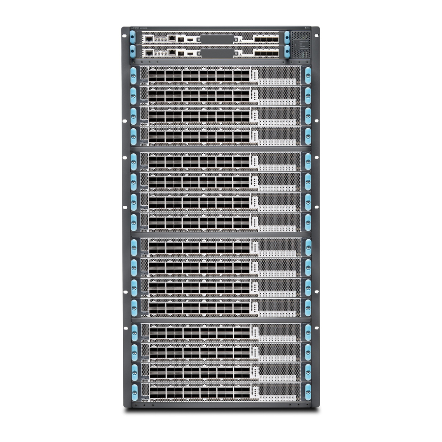
Chassis Description The MX10016 is 21 U tall. Two MX10016 chassis can fit in a standard 42 U rack when there is adequate cooling and power. All key MX10016 components are field-replaceable units (FRUs). Figure 1 on page 23 illustrates the components visible from the front of the chassis. - Page 23 Figure 2 on page 24 illustrates the components that are visible from the rear of the chassis. Figure 2: MX10016 Chassis Rear AC or DC power supplies ESD point — — Fan trays with redundant fans Protective earthing terminal —...
-
Page 24: Routing And Control Board
The Routing and Control Board (RCB) (see Figure 4 on page 26) contains a Routing Engine and is responsible for the system management and control in the MX10016. See “MX10016 Routing and Control Board” on page 75. RCBs are FRUs that are installed in the front of the chassis in the slots labeled CB0 and CB1. The base configuration has a single RCB while the fully redundant configuration has two RCBs. -
Page 25: Line Card (Mx10K-Lc2101)
Figure 4: MX10016 Routing and Control Board Line Card (MX10K-LC2101) The MX10016 has 16 horizontal line card slots and supports line rates for each line card. The line cards include a Packet Forwarding Engine and Ethernet interfaces enclosed in a single assembly. The MX10016 line card architecture is based on a number of identical, independent Packet Forwarding Engine slices, each with 400 Gbps full-duplex throughput. -
Page 26: Cooling System
When all the SFBs are installed, the MX10016 router has a net switching capacity of 2.4 terabytes per second (bidirectional). See “MX10016 Switch Fabric Board” on page... -
Page 27: Power Supplies
Power supplies for the MX10016 router are fully redundant, load-sharing, and hot-removable and hot-insertable FRUs. Each MX10016 router with a base configuration has five power supplies; redundant configurations hold a maximum of ten AC or DC power supplies. Each power supply has an internal fan for cooling. - Page 28 CAUTION: Do not mix AC and DC power supplies in the same chassis. Figure 9: JNP10K-PWR-AC Power Supply Figure 10: JNP10K-PWR-AC2 Power Supply...
- Page 29 Figure 11: JNP10K-PWR-DC Power Supply Figure 12: JNP10K-PWR-DC2 Power Supply Table 3 on page 30 provides an overview of the differences among the power supplies. Table 3: Power Supply Overview Power Supply Model Input Type Wattage Power Bus JNP10K-PWR AC AC only 2700 W Standard or enhanced...
-
Page 30: Software On Mx10016
The MX10016 router runs Junos OS, which provides Layer 3 routing services. The same Junos OS code base that runs on the MX10016 router also runs on all Juniper Networks M Series, MX Series, and T Series routers and SRX Series Services Gateways. - Page 31 Table 4: MX10016 Hardware Configurations (continued) Router Configuration Configuration Components Redundant AC configuration Chassis, including power bus Two Routing and Control Boards MX10016-PREMIUM Two fan tray controllers Two fan trays Ten 2700 W AC power supplies Six SFBs Sixteen line card cover panels...
-
Page 32: Mx10016 Component Redundancy
MX10016 Component Redundancy The MX10016 router is designed so that no single point of failure can cause the entire system to fail. The following major hardware components in the redundant configuration provide redundancy: Routing and Control Board (RCB)—The RCB consolidates the Routing Engine function with the control plane function in a single unit. - Page 33 Table 5: CLI Equivalents of Terms Used in Documentation for MX10016 Routers (continued) Hardware Item in Item (CLI) Description (CLI) Value (CLI) Documentation Additional Information Routing and CB (n) n is a value in the range “MX10016 Routing and Control of 0–1.
-
Page 34: Mx10016 Chassis
The MX10016 modular chassis is a rigid sheet-metal structure that houses the field-replaceable units (FRUs). You can mount up to two MX10016 chassis in a standard 19-in. four-post (42 U) rack, provided the rack can handle the combined weight and there is adequate power and cooling.Table 6 on page 36... - Page 35 Table 6: MX10016 Chassis Physical Specifications Description Weight Height Width Depth Chassis, spare 220 lb 36.6 in. 17.4 in. (44.2 cm) 35 in. (99.79 kg) (92.96 cm) (88.9 cm) NOTE: The outer edges of the mounting-bracket flange extend the width to 19 in. (48.3 cm).
- Page 36 Do not use the handles to lift the chassis, even when the chassis is empty. See “Installing an MX10016 into a Four-Post Rack” on page 139 for instructions for properly moving a loaded chassis.
-
Page 37: Mx10016 Field-Replaceable Units
Hot-pluggable—You can remove and replace these components without powering off the router, but the routing function is interrupted until you replace the component. Table 7 on page 38 lists the FRUs and their types for the MX10016 routers. Table 7: Field-Replaceable Units in an MX10016 Router Type Power supplies Hot-insertable and hot-removable. -
Page 38: Mx10016 Status Panel Leds
Starting in May 2019, new chassis ship with an enhanced power bus to support the power needs of higher wattage line cards. The status panel of the MX10016 shows the overall status of the chassis through a set of five bi-color LEDs (see Figure 14 on page 40 for a chassis with the original power bus). - Page 39 Figure 15 on page 40). Figure 15: Status Panel on Chassis with the Enhanced Power Bus Table 8 on page 40 describes the status panel LEDs. Table 8: Status Panel LEDs in an MX10016 Router Name Color State Description Power supplies...
- Page 40 Table 8: Status Panel LEDs in an MX10016 Router (continued) Name Color State Description Fans Green On steadily The fans and the fan tray controllers are online and operating normally. Yellow On steadily There is an error in a fan or in one of the fan tray controllers.
-
Page 41: Mx10016 Optional Equipment
MX10016 Optional Equipment The MX10016 router supports the cable management system as an optional piece of equipment. The cable management system (see Figure 16 on page 43) enables you to route optical cables away from the line card ports for better airflow through the chassis. - Page 42 Figure 16: MX10016 Cable Management System The cable management system is comprises a set of handle extensions and a tray that snaps to the extensions (see Figure 17 on page 43) for an individual line card. The handle extensions can be used with or without the cable tray.
-
Page 43: Mx10016 Cooling System
MX10016 Routing and Control Board | 75 MX10016 Switch Fabric Board | 80 MX10016 Power System | 57 MX10016 Cooling System IN THIS SECTION MX10016 Cooling System and Airflow | 45 MX10016 Fan Tray LEDs and Fan Tray Controller LEDs | 50... -
Page 44: Mx10016 Cooling System And Airflow
The cooling system in an MX10016 chassis consists of two fan trays and two fan tray controllers. An MX10016 has an air filter on the front panel. The fans in each fan tray are numbered 0 through 10. Two fan tray models and their associated fan tray controllers are available. All models are hot-insertable and hot-removable. -
Page 45: Mx10016 Fan Trays
The JNP10016-FAN2 and JNP10016-FAN2-CTRL are optimized to work best in the enhanced chassis, but are backwards compatible to work in the standard chassis. To determine which chassis you have, see “MX10016 Status Panel LEDs” on page MX10016 Fan Trays Each fan tray is a hot-insertable and hot-removable FRU. Each fan tray contains 21 fans (0-20), a non-removable Control Board, and LEDs. -
Page 46: Mx10016 Fan Tray Controllers
The internal fan control board in each fan tray contains LEDs for the associated fan tray controllers and LEDs for the three SFBs directly behind the fan tray. MX10016 Fan Tray Controllers Two fan tray controllers provide the control logic and power to hot-insert and hot-remove a fan tray. The fans in each fan tray are numbered 0 through 20. - Page 47 Fan Tray 0 Fan 11 7650 Spinning at normal speed Fan Tray 0 Fan 12 7800 Spinning at normal speed Fan Tray 0 Fan 13 7650 Spinning at normal speed Fan Tray 0 Fan 14 7650 Spinning at normal speed Fan Tray 0 Fan 15 7650 Spinning at normal speed...
-
Page 48: Airflow Direction In An Mx10016
Control Boards and line cards, through the Switch Fabric Boards (SFBs), and exits from the fan trays and the power supplies. This airflow is called port-to-FRU cooling or airflow out (AFO). See Figure 20 on page Figure 20: Airflow Through an MX10016... -
Page 49: Mx10016 Fan Tray Leds And Fan Tray Controller Leds
You can check the status of the fans by viewing the LEDs on each fan tray. See “MX10016 Fan Tray LEDs and Fan Tray Controller LEDs” on page You cannot replace a single fan. If one or more fans fail, you must replace the entire fan tray. - Page 50 Figure 21: Fan Tray LEDs on an MX10016 Fan status LED SFB status (SFB 0 through SFB 2 for the left fan tray — — and SFB 3 through 5 for the right fan tray) Fan tray controller status —...
- Page 51 Table 11: Fan Tray LEDs on an MX10016 (continued) Name Color State Description Fan tray controller status Green On steadily The fan tray controller is online and is operating normally. Green Blinking The beacon feature is enabled. This feature is enabled using the request chassis beacon command.
- Page 52 Table 11: Fan Tray LEDs on an MX10016 (continued) Name Color State Description SFB 1 status Green On steadily The center SFB behind the left fan tray is online. Green Blinking The beacon feature is enabled. This feature is enabled using the request chassis beacon command.
- Page 53 Table 11: Fan Tray LEDs on an MX10016 (continued) Name Color State Description SFB 3 status Green On steadily The left-most SFB behind the right fan tray is online. Green Blinking The beacon feature is enabled. This feature is enabled using the request chassis beacon command.
-
Page 54: Mx10016 Fan Tray Controller Leds
Table 11: Fan Tray LEDs on an MX10016 (continued) Name Color State Description SFB 5 status Green On steadily The right-most SFB behind the right fan tray is online. Green Blinking The beacon feature is enabled. This feature is enabled using the request chassis beacon command. - Page 55 Table 12: Fan Tray Controller LEDs on an MX10016 Name Color State Description Fan controller power Green On steadily The fan tray controller has power and is operating normally. Yellow Blinking A power error has been detected in the fan tray controller. Replace the fan tray controller as soon as possible.
-
Page 56: Mx10016 Power System
All of the power supplies are hot-insertable and hot-removable, field-replaceable units (FRUs). In the MX10016, you can install up to 10 power supplies in the slots labeled PEM 0 through PEM 9 (top to bottom) located in the rear of the chassis. You can install the power supplies in any slot. -
Page 57: Jnp10K-Pwr-Ac Power Supply
JNP10K-PWR-AC Power Supply The JNP10K-PWR-AC power supplies are hot-insertable, hot-removable, field-replaceable units (FRUs). In an MX10016, you can install up to 10 power supplies in the slots labeled PSU 0 through PSU 9. You can install the power supplies in any slot. - Page 58 NOTE: The base configuration of MX10016 routers are shipped with five power supplies. Cover are installed over the remaining power supply slots. You can add additional power supplies to base configuration routers as necessary.
- Page 59 AC appliance inlet on the faceplate. The adjustment nut holds the power cord in the correct position. For instructions for installing the power cord retainers, “Connecting AC Power to an MX10016” on page 148.
-
Page 60: Jnp10K-Pwr-Ac2 Power Supply
Each power supply has its own fan and is cooled by its own internal cooling system. Hot air exhausts from the rear of the chassis. JNP10K-PWR-AC2 Power Supply The JNP10K-PWR-AC2 power supply is a high-capacity, high-line model that is designed to support either AC or DC systems in either a low power or high power mode. -
Page 61: Jnp10K-Pwr-Dc Power Supply
WARNING: The router is pluggable type A equipment installed in a restricted-access location. It has a separate protective earthing terminal on the chassis that must be connected to earth ground permanently to ground the chassis adequately and protect the operator from electrical hazards. CAUTION: Before you begin installing the router, ensure that a licensed electrician has attached an appropriate grounding lug to the grounding cable that you supply. - Page 62 JNP10K-PWR-AC2—An AC, high-voltage alternating current (HVAC,) or high-voltage direct current (HVDC) power supply. In high power mode, this power supply provides 12.3 V, 5000 W with a single feed and 5500 W with dual feeds. For details on this power supply, see “JNP10K-PWR-AC2 Power Supply”...
- Page 63 DC power feed to provide redundancy. Only one power feed is operational at a time. DC power models employ an electronic A-B input selection. The MX10016 power system provides 2N source redundancy. If one power source fails, the electronic A-B input selection routes the power supply to the alternate source.
- Page 64 DC feed. The chosen breaker should be sized to deliver 60 A of input current. Each power supply connects to the combined power rail in an MX10016 router. The power rail distributes the output power produced by the power supplies to different router components. Each DC power supply provides power to all the components in the router.
-
Page 65: Jnp10K-Pwr-Dc2 Power Supply
NOTE: Route all the DC power supply cords away from the fan trays. Make sure that the power cords do not obstruct the fan trays. JNP10K-PWR-DC power supplies can use the standard bus or the enhanced bus. A JNP10K-PWR-DC power supply can operate with only one input DC feed connected. The Routing Control Board only enables the components for which sufficient power is available. - Page 66 Using a grounding cable with an incorrectly attached lug can damage the router. NOTE: DC power supplies are shipped only in the redundant configuration of MX10016 routers. For details about different chassis configurations, see “MX10016 Components and Configurations”...
-
Page 67: Jnp10K-Pwr-Ac Power Supply Leds
An AC power supply, JNP10K-PWR-AC, has four LEDs on its faceplate: INP1, INP2, PWR OK, and FAULT. These LEDs display information about the status of the power supply. See Figure 29 on page Figure 29: LEDs on an , JNP10K-PWR-AC, Power Supply in an MX10016 Router FAULT INP2–Source input 2 —... -
Page 68: Jnp10K-Pwr-Ac2 Power Supply Leds
Table 16: LEDs on an , JNP10K-PWR-AC, Power Supply in an MX10016 (continued) Color State Description PWR OK Green On steadily AC power output is within normal operating range. Yellow Blinking AC power output is out of the normal operating range. - Page 69 Figure 30: LEDs on a JNP10K-PWR-AC2 HVDC Power Supply ! FAULT 2 INP2–Source input 1 — — OK PWR OK 1 INP1–Source input 0 — — NOTE: Physical markings on the power supply are INP1 and INP2. These markings correspond to INP0 and INP1 in the show chassis power output (see Table 17 on page 70).
-
Page 70: Jnp10K-Pwr-Dc Power Supply Leds
Table 18: Interpreting JNP10K-PWR-AC2 LEDs Color State Description INP1 or INP0 in CLI output Yellow Blinking The input voltage is present, but is not within normal operating range. Green Solid The input voltage is present and within normal operating range. Unlit The power supply is switched off;... - Page 71 INP2–Source input 2 FAULT — — Table 19 on page 72 describes the LEDs in on the JNP10K-PWR-DC power supply in an MX10016 chassis. Table 19: LEDs on a DC Power Supply in an MX10016 Color State Description INP1 or INP2...
-
Page 72: Jnp10K-Pwr-Dc2 Power Supply Leds
Table 19: LEDs on a DC Power Supply in an MX10016 (continued) Color State Description FAULT On Steadily The power supply has failed and must be replaced. Unlit The power supply is functioning normally. Only one input is powered and the enable switch for the input that is not powered is set to ON. - Page 73 Power supply is functioning normally. Or, only one input is powered and the enable switch for the input that is not powered is set to ON. See “Connecting DC Power to an MX10016” on page 149 for more information on the enable switches.
-
Page 74: Mx10016 Routing And Control Board
Routing and Control Board Functions | 76 Routing and Control Board Components | 76 The Routing and Control Board (RCB) is responsible for system management in an MX10016 router (see Figure 33 on page 76). The chassis can run with one or two RCBs. The base configuration ships with one... -
Page 75: Routing And Control Board Functions
RCB while a redundnat configuration ships with two RCBs. When two RCBs are installed, one functions as the master and the second as a backup. If the master RCB is removed, the backup becomes the master if graceful Routing Engine switchover (GRES) is configured. MX10016 supports the following Routing Engines: JNP10K-RE1 JNP10K-RE1-LT... - Page 76 — BITS-0 clock port Online/Offline button — — GPS clock ports USB port — — XGE-0 and XGE-1 Juniper Control System (JCS) ports Management (MGMT) ports — — ToD—Time-of-day (TOD) port Console (CONSOLE) port — — BITS-1 clock port —...
-
Page 77: Mx10016 Routing And Control Board Leds
MX10016 Routing and Control Board LEDs Figure 35 on page 78 shows the LEDs on the Routing and Control Boards (JNP10K-RE1). Figure 35: Routing and Control Board LEDs RCB status panel LEDs—PWR, STS, and MASTER Clock LEDs—BITS-0, and BITS-1 —... - Page 78 Figure 36: Management Port LEDs on an RCB Status LED (RJ-45) LINK LED — — Activity LED (RJ-45) — Table 22 on page 79 describes the RJ-45 management port and SFP LEDs. Table 22: RJ-45 Management Port LEDs on the Routing and Control Board Color State Description...
-
Page 79: Mx10016 Switch Fabric Board
The drive is active. Dark Unlit A drive is not installed. RELATED DOCUMENTATION Removing and Installing Routing and Control Boards MX10016 Switch Fabric Board IN THIS SECTION MX10016 Switch Fabric Board Description | 81 Switch Fabric Board LEDs | 83... -
Page 80: Mx10016 Switch Fabric Board Description
RCBs in the front and the fan trays in the rear. When all six SFBs are installed, the MX10016 has a net switching capacity of 96 Tbps. MX10016 Switch Fabric Board Description The SFBs make up the switching plane. - Page 81 You must remove one of the fan trays in order to view the SFBs. The SFBs are numbered from left to right SFB0 to SFB5. See Figure 38 on page Figure 38: SFBs Installed in an MX10016 Fan tray controllers Switch Fabric Boards —...
-
Page 82: Switch Fabric Board Leds
Switch Fabric Board LEDs The Switch Fabric Board (SFB) has two status LEDs at the top of each board. See Figure 39 on page Figure 39: Switch Fabric Board LEDs Table 26 on page 83 describes the functions of these LEDs. Table 26: SFB LEDs Label Color... -
Page 83: Line Card (Mx10K-Lc2101)
RELATED DOCUMENTATION Handling and Storing MX10016 Line Cards, RCBs, and SFBs | 209 Removing and Installing MX10016 Switch Fabric Boards | 208 Line card (MX10K-LC2101) The MX10K-LC2101 line card is a fixed configuration MPC and it does not contain separate slots for Modular Interface Cards (MICs). - Page 84 Cables and TIP: You can use the Hardware Compatibility Tool to find information about the pluggable transceivers supported connectors on your Juniper Networks device. The list of supported transceivers for the MX Series is located at MX Series Supported Transceivers.
-
Page 85: Site Planning, Preparation, And Specifications
C HAPTER Site Planning, Preparation, and Specifications MX10016 Site Preparation Overview | 89 MX10016 Power Planning | 96 MX10016 Transceiver and Cable Specifications | 115 MX10016 Alarm and Management Cable Specifications and Pinouts | 120... -
Page 87: Mx10016 Site Preparation Overview
Environmental Requirements and Specifications | 90 General Site Guidelines | 91 Site Electrical Wiring Guidelines | 92 MX10016 Rack Requirements | 93 Clearance Requirements for Airflow and Hardware Maintenance for an MX10016 | 95 Site Preparation Checklist The checklist in Table 27 on page 89 summarizes the tasks you need to perform when preparing a site for an MX10016 installation. -
Page 88: Environmental Requirements And Specifications
Plan the cable routing and management. Environmental Requirements and Specifications The MX10016 router must be installed in a four-post rack. It must be housed in a dry, clean, well-ventilated, and temperature-controlled environment. Follow these environmental guidelines: The site must be as dust-free as possible, because dust can clog air intake vents and filters, reducing the efficiency of the router cooling system. -
Page 89: General Site Guidelines
Designed to comply with Zone 4 earthquake requirements per NEBS GR-63-CORE, Issue 3. NOTE: Install the MX10016 router only in restricted areas, such as dedicated equipment rooms and equipment closets, in accordance with Articles 110-16, 110-17, and 110-18 of the National Electrical Code, ANSI/NFPA 70. -
Page 90: Site Electrical Wiring Guidelines
Efficient operation of the device requires proper site planning and maintenance and proper layout of the equipment, rack, or cabinet (if used), and wiring closet. To plan and create an acceptable operating environment for your device and prevent environmentally caused equipment failures: Keep the area around the chassis free from dust and conductive material, such as metal flakes. -
Page 91: Mx10016 Rack Requirements
OSP cabling. The addition of primary protectors is not sufficient protection to connect these interfaces metallically to OSP wiring. MX10016 Rack Requirements The MX10016 chassis is designed to be installed in four-post racks. Table 30 on page 94 provides the rack... - Page 92 Ensure that the rack is strong enough to support the weight of the router and cabling. Ensure that the spacing of the rails and adjacent racks allows for proper clearance around the router and rack. See “Clearance Requirements for Airflow and Hardware Maintenance for an MX10016” on page...
-
Page 93: Clearance Requirements For Airflow And Hardware Maintenance For An Mx10016
Clearance Requirements for Airflow and Hardware Maintenance for an MX10016 When planning the site for an MX10016 router installation, you must allow sufficient clearance around the installed chassis for cooling and maintenance (see Figure 40 on page 95 for MX10016). -
Page 94: Mx10016 Power Planning
Leave at least 24 in. (61 cm) both in front of and behind the MX10016 for service personnel to remove and install hardware components. To be NEBS GR-63 compliant, allow at least 30 in. (76.2 cm) in front of the rack and 24 in. -
Page 95: Power Requirements For Mx10016 Components
1425 W at 104° F (40° C) Gigabit Ethernet mode) Calculating Power Requirements for an MX10016 Use the information in this topic to calculate the power requirements of your MX10016 configuration and the number of power supplies required for different MX10016 router configurations. -
Page 96: How To Calculate The Power Consumption Of Your Mx10016 Configuration
This topic describes these tasks: How to Calculate the Power Consumption of Your MX10016 Configuration | 98 How to Calculate the Number of Power Supplies Required for Your MX10016 Configuration | 100 How to Calculate the Power Consumption of Your MX10016 Configuration Use the following procedure to determine the maximum power you need to supply to the router. - Page 97 15275 W 18525 W 16450 W 19950 W 17625 W 21375 W 18800 W 22800 W For example, for an MX10016 with 16 MX10K-LC2101 line cards, the maximum power consumption at 400-Gigabit Ethernet mode is: 16 * 1425 W= 22800 W...
-
Page 98: How To Calculate The Number Of Power Supplies Required For Your Mx10016 Configuration
Use this procedure to calculate the number of power supplies required by your router configuration. The minimum power configuration for MX10016 routers is three power supplies.. However, using the calculated minimum power configuration does not prevent the system from raising a power alarm. To ensure you do not log power alarms, you must configure your router for n+1 power supplies. - Page 99 Table 34: Total Power Available With With With With With With Ten Power Three Four Five With Six Seven Eight Nine Supplies Power Supply Power Power Power Power Power Power Power (redundancy Module Models Supplies Supplies Supplies Supplies Supplies Supplies Supplies only) JNP10K-PWR-AC...
-
Page 100: Jnp10K-Pwr-Ac Power Specifications
In the previous examples, we calculated that an MX10016 AC power system requires 22800 W with 16 line cards. In this example, we calculate the total power available for this configuration: (25450 W) / (2700 W) = 9.42... -
Page 101: Jnp10K-Pwr-Ac2 Power Specifications
6.8 lb 3.08 kg) JNP10K-PWR-AC2 Power Specifications MX10008 and MX10016 redundant configuration routers can use either AC or DC power supplies; base configuration routers are AC only. The JNP10K-PWR-AC2 power supply supports AC, HVAC, and HVDC. Table 37 on page 103 lists the power specifications for the AC power supply (JNP10K-PWR-AC) used in a MX10000 chassis. -
Page 102: Mx10016 Power Cord Specifications
Value Depth 15.1 in. (38.35 cm) Weight 15.1 in. (38.35 cm) MX10016 Power Cord Specifications IN THIS SECTION JNP10K-PWR-AC Power Cable Specifications | 105 JNP10K-PWR-AC2 Power Cable Specifications | 107 JNP10K-PWR-AC2 Power Cable Specifications for 30-A Input | 110 Each AC power supply has two independent 16 A rated AC inlets on the faceplate. Most sites distribute power through a main conduit that leads to frame-mounted power distribution panels, one of which can be located at the top of the rack that houses the router. -
Page 103: Jnp10K-Pwr-Ac Power Cable Specifications
JNP10K-PWR-AC see “JNP10K-PWR-AC Power Cable Specifications” on page 105 JNP10K-PWR-AC2 with 20-A input, see “JNP10K-PWR-AC2 Power Cable Specifications” on page 107 JNP10K-PWR-AC2 with 30-A input, see “JNP10K-PWR-AC2 Power Cable Specifications for 30-A Input” on page 110 JNP10K-PWR-AC Power Cable Specifications Table 39 on page 106 lists the AC power cord specifications for JNP10K-PWR-AC for various countries and regions. - Page 104 Table 39: AC Power Cord Specifications for JNP10K-PWR-AC Power Supplies Electrical Juniper Model Country/Region Specifications Plug Standards Number Graphic Argentina 250 VAC, 16 A, IRAM Type RA/3/20 CBL-EX-PWR-C19-AR 50 Hz Australia 250 VAC, 15 A, AS/NZS 3112 Type CBL-EX-PWR-C19-AU 50 Hz...
-
Page 105: Jnp10K-Pwr-Ac2 Power Cable Specifications
Table 39: AC Power Cord Specifications for JNP10K-PWR-AC Power Supplies (continued) Electrical Juniper Model Country/Region Specifications Plug Standards Number Graphic Korea 250 VAC, 16 A, CEE (7) VII Type VIIG CBL-EX-PWR-C19-KR 50 Hz North America 250 VAC, 16 A, NEMA 6–20 Type... - Page 106 WARNING: Do not run JNP10K-PWR-AC2 power supplies using 20-A cables if connected to 30-A input. Table 40: JNP10K-PWR-AC2 Power Cable Specifications for 20-A Input Spare Juniper Locale Cord Set Rating Plug Standards Model Number Graphic Argentina 16 A, 250 VAC...
- Page 107 Table 40: JNP10K-PWR-AC2 Power Cable Specifications for 20-A Input (continued) Spare Juniper Locale Cord Set Rating Plug Standards Model Number Graphic India 16 A, 250 VAC SANS 164/1 CBL-JNP-SG4-SA Israel 16 A, RA, 250 VAC SI 32/1971 Type CBL-JNP-SG4-IL IL/3G...
-
Page 108: Jnp10K-Pwr-Ac2 Power Cable Specifications For 30-A Input
JNP10K-PWR-AC2 orders. An example of the right-angle cable and connector is shown in Figure 43 on page 111. For connection to AC systems, Juniper provides a cable with either a NEMA 30-A connector (Figure 41 on page 110) or an IEC 330P6W connector (Figure 42 on page 110). - Page 109 Table 41: 30-A Cabling Options Cord Set Plug Spare Juniper Model Locale Rating Standards Connector Number HVAC/HVDC 30- A, UL 950 and Anderson/straight to CBL-PWR2-BARE power cord 400 VAC IEC 60950 bare wire HVAC/HVDC 30-A, UL 950 and Anderson/right-angle CBL-PWR2-BARE-RA...
-
Page 110: Jnp10K-Pwr-Dc Power Specifications
The DC power supply (JNP10K-PWR-DC) is supported only in the MX10016 redundant configuration. Table 42 on page 112 lists the power specifications for the DC power supply used in an MX10016 chassis. Table 42: Power Specifications for the JNP10K-PWR-DC Power Supply... -
Page 111: Mx10016 Grounding Cable And Lug Specifications
Weight 8.1 lb (3.67 kg) MX10016 Grounding Cable and Lug Specifications For installations that require a separate grounding conductor to the chassis, the router must be adequately grounded before power is connected to ensure proper operation and to meet safety and electromagnetic... - Page 112 6 AWG (13.3 mm²) stranded wire. The grounding cable that you provide for an MX10016 must be the same size or heavier than the input wire of each power supply. Minimum recommendations are 6 AWG (13.3 mm²) stranded copper wire, Class B;...
-
Page 113: Mx10016 Transceiver And Cable Specifications
Optical Transceiver and Cable Support The MX10016 router has 16 slots for the line cards that can support a maximum of 2304 ports as 10-Gigabit Ethernet ports, 576 ports as 40-Gigabit Ethernet ports, or 480 ports as 100-Gigabit Ethernet ports. Each of the network ports on the port panel supports quad small form-factor pluggable plus (QSFP+) transceivers and QSFP28 transceivers. -
Page 114: Cable Specifications For Console And Management Connections
Cable Specifications for Console and Management Connections Table 46 on page 116 lists the specifications for the cables that connect the MX10016 router to a management device. NOTE: The MX10016 router can be configured with SFP management ports that support 1000BASE-SX transceivers. -
Page 115: Signal Loss In Multimode And Single-Mode Fiber-Optic Cables
To determine the power budget and power margin needed for fiber-optic connections, you need to understand how signal loss, attenuation, and dispersion affect transmission. The MX10016 router uses various types of network cables, including multimode and single-mode fiber-optic cables. Signal Loss in Multimode and Single-Mode Fiber-Optic Cables Multimode fiber is large enough in diameter to allow rays of light to reflect internally (bounce off the walls of the fiber). -
Page 116: Calculating The Fiber-Optic Cable Power Budget For An Mx10016
The optical power budget must allow for the sum of component attenuation, power penalties (including those from dispersion), and a safety margin for unexpected losses. Calculating the Fiber-Optic Cable Power Budget for an MX10016 Calculate the link's power budget when planning fiber-optic cable layout and distances to ensure that fiber-optic connections have sufficient power for correct operation. - Page 117 See the specification for your receiver to find the maximum receiver input power. Before calculate the power margin, see “Calculating the Fiber-Optic Cable Power Budget for an MX10016” on page 118. To calculate the worst-case estimate for the power margin (P ) for the link: 1.
-
Page 118: Mx10016 Alarm And Management Cable Specifications And Pinouts
MX10016 Alarm and Management Cable Specifications and Pinouts IN THIS SECTION Console Port Connector Pinouts for an MX10016 Router | 120 USB Port Specifications for an MX10016 | 121 Management Port Connector Pinouts for an MX10016 | 122 Console Port Connector Pinouts for an MX10016 Router The console port (labeled CON) on the RCB panel is an RS-232 serial interface that uses an RJ-45 connector to connect to a console management device. -
Page 119: Usb Port Specifications For An Mx10016
If your laptop or PC does not have a DB-9 male connector pin and you want to connect your laptop or PC directly to an MX10016 router, use a combination of the RJ-45 cable and RJ-45 to DB-9 adapter supplied with the device and a USB to DB-9 male adapter. You must provide the USB to DB-9 male adapter. -
Page 120: Management Port Connector Pinouts For An Mx10016
Management Port Connector Pinouts for an MX10016 The 1000BASE-T RJ-45 management ports use an RJ-45 connector to connect either to the control plane and management network in an MX10016 router, or to a management device for out-of-band management. Table 49 on page 122 provides the pinout information of the RJ-45 management port connector. - Page 121 Table 49: RJ-45 Management Port Connector Pinouts for an MX10016 (continued) Signal Description TRP2– Transmit/receive data pair 2 TRP4+ Transmit/receive data pair 4 TRP4– Transmit/receive data pair 4 RELATED DOCUMENTATION MX10016 Routing and Control Board LEDs | 78...
-
Page 122: Initial Installation And Configuration
MX10016 Installation Overview | 127 Unpacking an MX10016 Router and Components | 128 Installing the Mounting Hardware | 136 Installing an MX10016 into a Four-Post Rack | 139 Connecting an MX10016 to Power | 145 Connecting an MX10016 to External Devices | 150... -
Page 124: Mx10016 Installation Overview
The chassis is bolted to the pallet base. You can install an MX10016 router in a standard 19 in. (483 mm) equipment rack by using the supplied rack mount kit and the flanges attached to the chassis. -
Page 125: Unpacking An Mx10016 Router And Components
The chassis is maximally protected inside the shipping box. Do not unpack it until you are ready to begin the installation. Ensure that you have the following parts and tools available to unpack the MX10016: A 13/32 in. (10 mm) open-end wrench or socket wrench to remove the bracket bolts from the shipping... - Page 126 The shipper has the option to ship either the front panel separately or to ship the front panel along with the chassis. If the front panel arrives with the chassis, set aside the front panel box until you are ready to verify the contents of the order.
- Page 127 9. Unpack the accessory box, and lay out the contents so that they are ready for use. 10. Verify that your order includes all appropriate parts. See “MX10016 Components and Configurations” on page 31 “Comparing the MX10016 Order to the Packing List” on page 132. for information about base configurations and redundant configurations.
-
Page 128: Unpacking Line Cards, Routing And Control Boards, And Switch Fabric Boards
“Prevention of Electrostatic Discharge Damage” on page 303. Ensure that you know how to handle and store the component. See “Handling and Storing MX10016 Line Cards, RCBs, and SFBs” on page 209). To unpack an RCB, SFB, or line card, see... -
Page 129: Comparing The Mx10016 Order To The Packing List
Figure 46: Unpacking a Line Card Foam packing material Paper packaging and electrostatic bag — — Comparing the MX10016 Order to the Packing List Use the following procedure to compare the sales order and packing list against the contents of the chassis shipping crate. - Page 130 The packing list specifies the part number and description of each part in your order. If any part on the packing list is missing, contact your customer service representative, or contact Juniper Networks Customer Care from within the U.S. or Canada by telephone at 1-888-314-5822. For international-dial or direct-dial options in countries without toll-free numbers, see https://www.juniper.net/support/requesting-support.html.
- Page 131 Table 50: Parts Included in the Premium Redundant Configuration Order (continued) Component MX10016 Quantity Covers in the line card slots Accessory kit (see Table 52 on page 135) Rack mount kit (see Table 53 on page 136) Front panel kit (see...
- Page 132 Table 51: Parts Included in a Base Configuration Order (continued) Component MX10016 Quantity Documentation roadmap card 3. Compare the contents of the accessory kit with Table 52 on page 135 Table 52: MX10016 Accessory Kit Quantity Component AC Configurations DC Configurations Warranty card...
-
Page 133: Installing The Mounting Hardware
Documentation roadmap card SEE ALSO MX10016 Components and Configurations | 31 Installing the Mounting Hardware An MX10016 router can be installed in a four-post rack or in an open-frame rack. Install the mounting hardware on the rack before installing the router. - Page 134 EX-MOD-RMK-4POST, can be ordered as a spare. NOTE: An MX10016 cannot be installed in a two-post installation rack. The main pieces of the rack mount kit are: One left base bracket. The bracket is labeled LEFT FRONT on the side of the bracket that faces the interior of the rack, near the holes for attaching the bracket to the rack.
- Page 135 rear brackets should overlap. Use four mounting screws appropriate for your rack to attach the rear bracket to the rack. 5. Connect left base bracket and rear brackets (see Figure 47 on page 138): a. Insert six of the flat-head screws provided with the mounting brackets into the overlapping bracket holes.
-
Page 136: Installing An Mx10016 Into A Four-Post Rack
Installing the Front Panel on an MX10016 | 142 Mounting an MX10016 in a Four-Post Rack Using a Mechanical Lift Because of the router's size and weight, an MX10016 can be installed safely only by using a mechanical lift. CAUTION: Do not install line cards in the chassis until after you mount the chassis securely in a rack or cabinet. - Page 137 For details, see “Clearance Requirements for Airflow and Hardware Maintenance for an MX10016” on page 2. Load the router onto the mechanical lift, making sure that it rests securely on the lift platform.
- Page 138 Figure 48: Loading an MX10016 into a Rack Using a Mechanical Lift 3. Using the lift, align the router in front of the rack, centering it in front of the base brackets. 4. Lift the chassis approximately 0.75 in. (1.9 cm) above the surface of the base brackets. Align the chassis as close as possible to the base brackets.
-
Page 139: Installing The Front Panel On An Mx10016
Installing the Front Panel on an MX10016 The front panel is required on the MX10016 router to protect fiber-optic cabling and to provide additional protection from electromagnetic interference (EMI). The front panel can be installed with or without the... - Page 140 3. Use the Phillips screwdriver to attach two mounting screws to the right base bracket at the bottom right side of the chassis frame. 4. Use the Phillips screwdriver to attach two mounting screws to the latch bracket at the top-left of the chassis frame (see Figure 51 on page 144 for MX10016 installation).
- Page 141 Figure 51: Attaching Front Panel Brackets on an MX10016 5. Use the Phillips screwdriver to attach the final two mounting screws to attach the second latch bracket to the top right of the chassis frame so there are brackets on all four corners of the front of the chassis.
-
Page 142: Connecting An Mx10016 To Power
Figure 52: Front Panel Installation on an MX10016 Connecting an MX10016 to Power IN THIS SECTION Connecting an MX10016 to Earth Ground | 146 Connecting AC Power to an MX10016 | 148 Connecting DC Power to an MX10016 | 149... -
Page 143: Connecting An Mx10016 To Earth Ground
(see Figure 54 on page 148). Before you connect the protective earthing terminal of an MX10016 to earth ground, ensure that a licensed electrician has attached an appropriate grounding lug to the grounding cable. CAUTION: Using a grounding cable with an incorrectly attached lug can damage the router. - Page 144 3. Attach an ESD grounding strap to your bare wrist, and connect the strap to the ESD grounding point next to the earthing posts (see Figure 53 on page 147). Figure 53: ESD Point on the Rear of an MX10016 ESD point — 4. Remove the two screws on the chassis grounding point using a Phillips screwdriver.
-
Page 145: Connecting Ac Power To An Mx10016
Although this sequence can start incrementally with a single power supply, we recommend that you power on an MX10016 router with at least three power supplies. Before you begin connecting power to the router, be sure you understand how to prevent ESD damage (see “Prevention of Electrostatic Discharge Damage”... -
Page 146: Connecting Dc Power To An Mx10016
The overall process of powering on a DC-powered chassis involves the proper cabling of the individual power supplies, adding the power supplies to the chassis, and supplying power. Although this sequence can start incrementally with a single power supply, we recommend that you power on an MX10016 router with at least three power supplies. -
Page 147: Connecting An Mx10016 To External Devices
Connecting an MX10016 Router to a Management Console | 151 Connecting an MX10016 to a Network for Out-of-Band Management You can monitor and manage an MX10016 using a dedicated management channel. Each Routing and Control Board (RCB) of an MX10016 has two management ports: a 10/100/1000BASE-T RJ-45 port for copper connections and a 1-Gigabit SFP port for fiber connections. -
Page 148: Connecting An Mx10016 Router To A Management Console
Figure 55: Connecting an MX10016 to a Network for Out-of-Band Management Connecting an MX10016 Router to a Management Console An MX10016 router has a console port with an RJ-45 connector. Use the console port to connect the device to a management console or to a console server. -
Page 149: Configuring An Mx10016 Router
Figure 57: Connecting an MX10016 Router Directly to a Management Console Configuring an MX10016 Router You must perform the initial configuration of an MX10016 router through the console port by using the command-line interface (CLI). Before you begin connecting and configuring the router, set the following parameter values on the console server or PC: Baud Rate—9600... - Page 150 The management ports em0 (MGMT for RJ-45 connections), and em1 (also labeled MGMT for fiber connections) are located on the Routing and Control Boards of an MX10016. 9. (Optional) Configure the static routes to remote prefixes with access to the management port.
- Page 151 NOTE: When Telnet is enabled, you cannot log in to an MX10016 through Telnet using root credentials. Root login is allowed only for SSH access. 11. Commit the configuration to activate it on the router.
-
Page 152: Maintaining Components
Field-Replaceable Units in an MX10016 | 157 Removing and Installing Routing and Control Boards | 158 Removing and Installing MX10016 Cooling System Components | 162 Removing and Installing MX10016 Power System Components | 172 Removing and Installing MX10016 Switch Fabric Boards | 208... -
Page 154: Field-Replaceable Units In An Mx10016
Hot-pluggable—You can remove and replace these components without powering off the router, but the routing function is interrupted until you replace the component. Table 55 on page 157 lists the FRUs and their types for MX10016 routers. Table 55: FRUs in an MX10016 Router Type Power supplies Hot-insertable and hot-removable. -
Page 155: Removing And Installing Routing And Control Boards
OS release in which the transceivers were introduced. NOTE: If you have a Juniper Care service contract, register any addition, change, or upgrade of hardware components at https://www.juniper.net/customers/support/tools/updateinstallbase/. Failure to do so can result in significant delays if you need replacement parts. This note does not apply if you replace an existing component with the same type of component. -
Page 156: Removing A Routing And Control Board
Removing a Routing and Control Board An MX10016 can have one or two Routing and Control Boards (RCBs), depending on the configuration. You can install an RCB in either of the two top slots on the front of the chassis. -
Page 157: Installing A Routing And Control Board
7. If you are not replacing the RCB now, install a cover panel in the empty slot. Installing a Routing and Control Board An MX10016 can have one or two Routing and Control Boards (RCBs), depending on the configuration. RCBs can be installed in either of the two top slots on the front of the chassis. - Page 158 1. Wrap and fasten one end of an ESD strap around your bare wrist, and connect the other end of the strap to the ESD point on the front of an MX10016(see Figure 60 on page 161). Figure 60: ESD Point on the Front of an MX10016 MX 100 16 2.
-
Page 159: Removing And Installing Mx10016 Cooling System Components
Installing an MX10016 Fan Tray | 166 Removing an MX10016 Fan Tray Controller | 168 Installing an MX10016 Fan Tray Controller | 170 An MX10016 router has two independent, field-replaceable fan trays. Fan trays must be replaced within the duration mentioned in Table 56 on page... -
Page 160: Removing An Mx10016 Fan Tray
To install or remove the fan trays and fan tray controller, see the following sections: Removing an MX10016 Fan Tray An MX10016 has two independent, field-replaceable fan trays. Each fan tray is a hot-removable and hot-insertable field-replaceable unit (FRU); you can remove and replace the fan tray while the router is running without turning off power to the router or disrupting routing functions. - Page 161 ESD point on the rear left side of the chassis (see Figure 63 on page 164). Figure 63: ESD Point on the Rear of an MX10016 ESD point — 2. Loosen the four captive screws either by unscrewing with your thumb and forefinger or by using a Phillips screwdriver.
- Page 162 Figure 64: Removing a Fan Tray from an MX10016 4. Tilt the top of the fan tray forward. CAUTION: See the heat symbol on the fan tray. The fan tray handle and its surfaces, including the power supply handles may be hot. Wear proper protective, heat-resistant, gloves while removing the fan tray.
-
Page 163: Installing An Mx10016 Fan Tray
163. Installing an MX10016 Fan Tray An MX10016 chassis has two independent, field-replaceable fan trays. Each fan tray is a hot-removable and hot-insertable field-replaceable unit (FRU); you can remove and replace the fan tray while the router is running without turning off power to the router or disrupting routing functions. - Page 164 1. Wrap and fasten one end of an ESD strap around your bare wrist, and connect the other end of the strap to the ESD point on the rear left side of the chassis (see Figure 65 on page 167 Figure 65: ESD Point on the Rear of an MX10016 ESD point —...
-
Page 165: Removing An Mx10016 Fan Tray Controller
Figure 66: Installing a Fan Tray in an MX10016 Removing an MX10016 Fan Tray Controller For each of the two fan trays, there is a fan tray controller. Each controller is a hot-removable and hot-insertable field-replaceable unit (FRU); you can remove and replace one fan tray controller while the router is running without turning off power to the router or disrupting routing functions. - Page 166 An electrostatic bag or an antistatic mat A number 1 Phillips (+) screwdriver to loosen the captive screws 1. Remove the fan tray (see “Removing an MX10016 Fan Tray” on page 163). 2. Loosen the two captive screws on each side of the fan tray controller.
-
Page 167: Installing An Mx10016 Fan Tray Controller
4. Place the fan tray controller in an electrostatic bag or on an antistatic mat. Installing an MX10016 Fan Tray Controller Each fan tray of an MX10016 has a fan tray controller (see Figure 69 on page 170). Each controller is a hot-removable and hot-insertable field-replaceable unit (FRU). - Page 168 (see Figure 70 on page 171). Figure 70: Replacing an MX10016 Fan Tray Controller 3. Using a Phillips screwdriver, tighten the captive screws for the fan tray controller. 4. Replace the fan tray. See “Installing an MX10016 Fan Tray” on page...
-
Page 169: Removing And Installing Mx10016 Power System Components
How to Install a JNP10K-PWR-DC2 Power Supply | 200 How to Remove a JNP10K-PWR-AC Power Supply The JNP10K-PWR-AC power supply in an MX10016 router is a hot-removable and hot-insertable field-replaceable unit (FRU). You remove AC power supplies from the rear of the chassis. - Page 170 Do not leave the power supply slot empty for a long time while the router is operational. Either replace the power supply promptly or install a cover panel over the empty slot. To remove an AC power supply from an MX10016 router (see Figure 72 on page 174): 1.
- Page 171 9. If you are not replacing the power supply, install the cover panel over the slot. Figure 72: Removing a JNP10K-PWR-AC Power Supply from an MX10016 Keep latch in open position during removal.
-
Page 172: How To Install A Jnp10K-Pwr-Ac Power Supply
The JNP10K-PWR-AC power supply in an MX10016 chassis is a hot-insertable and hot-removable field-replaceable unit (FRU). You can install up to 10 power supplies in an MX10016 router chassis. All AC power supplies install in the rear of the chassis in the slots provided along the left side. - Page 173 1. Attach the electrostatic discharge (ESD) grounding strap to your bare wrist, and connect the strap to the ESD point on the chassis. There is an ESD point located next to the protective earthing terminal and below PSU 9 on the MX10016 (see Figure 73 on page 176).
- Page 174 7. Rotate the captive screw away from the faceplate of the power supply to release the latch. You can install a power supply in any slot labeled PSU 0 through PSU 9 on an MX10016. 8. Using both hands, place the power supply in the power supply slot on the rear of the chassis.
- Page 175 Figure 75: Installing an AC Power Supply in an MX10016 Keep latch in open position during installation. 12. Attach each power cord to a dedicated AC power source outlet. 13. Squeeze the two sides of the power cord retainer clip and insert the ends of the clip into the holes in the bracket on each side of the AC appliance inlets on the AC power supply faceplate.
-
Page 176: How To Remove A Jnp10K-Pwr-Ac2 Power Supply
20. Press the power switch to the on (|) position. How to Remove a JNP10K-PWR-AC2 Power Supply The JNP10K-PWR-AC2 power supply in an MX10016 chassis is a hot-removable and hot-insertable field-replaceable unit (FRU). You remove all power supplies from the rear of the chassis. -
Page 177: Caution: Before You Remove A Power Supply, Ensure That You Have Power Supplies Sufficient To Power The Router Left In The Chassis. See "Power Requirements For Mx10016 Components" On Page
Do not leave the power supply slot empty for a long time while the router is operational. Either replace the power supply promptly or install a cover panel over the empty slot. To remove a JNP10K-PWR-AC2 power supply from an MX10016 router:... - Page 178 PSU_9 on the MX10016 (see Figure 77 on page 181). Figure 77: ESD Point on an MX10016 Chassis Rear ESD point — 2. Flip the power | switch next to the appliance inlet on the power supply to the standby position.
- Page 179 Figure 78: Removing a JNP10K-PWR-AC2 from an MX10016 Chassis 6. Rotate the captive screw away from the faceplate of the power supply to release the latch. 7. Put on your heat protective gloves before removing the power supply from the chassis.
-
Page 180: How To Install A Jnp10K-Pwr-Ac2 Power Supply
The JNP10K-PWR-AC2 power supply in an MX10016 chassis is a hot-insertable and hot-removable field-replaceable unit (FRU). You can install up to 10 power supplies in a MX10016 router chassis. All power supplies install in the rear of the chassis in the slots provided along the left side. - Page 181 Save the cover for later use. See Figure 80 on page 184 for the MX10016. Figure 80: Removing the Power Supply Cover on an MX10016 3. Taking care not to touch power supply connections, remove the power supply from its bag.
- Page 182 10. Tighten the captive screw by turning it clockwise by using the Phillips (+) screwdriver, number 1. When the screw is completely tight, the latch locks into the router chassis. Figure 81: Installing a JNP10K-PWR-AC2 in an MX10016...
- Page 183 See Figure 82 on page 186 for an MX10016. Figure 82: Proper Load Balancing for JNP10K-PWR-AC2 Power Cables on an MX100016 12. For each power cable, insert the end of the cable with the Anderson connector into the JNP10K-PWR-AC2 power supply module.
-
Page 184: How To Remove A Jnp10K-Pwr-Dc Power Supply
16. Press the power switch to the on (|) position. How to Remove a JNP10K-PWR-DC Power Supply The JNP10K-PWR-DC power supply in an MX10016 chassis is a hot-removable and hot-insertable field-replaceable unit (FRU). You remove DC power supplies from the rear of the chassis. - Page 185 Do not leave a power supply slot empty for a long time while the router is operational. Either replace the power supply promptly or install a cover panel over the empty slot. To remove a JNP10K-PWR-DC power supply from an MX10016 router (see Figure 84 on page 190): 1.
- Page 186 3. Ensure that the power supply output switch, to the right of the captive screw, is set to the standby position. 4. Unscrew the captive screw of the latch counterclockwise by using the number 1 Phillips (+) screwdriver. 5. Rotate the captive screw away from the faceplate of the power supply to release the latch (see Figure 84 on page 190).
-
Page 187: How To Install A Jnp10K-Pwr-Dc Power Supply
The JNP10K-PWR-DC power supply in an MX10016 chassis is a hot-removable and hot-insertable field-replaceable unit (FRU). You can install up to 10 JNP10K-PWR-DC power supplies in an MX10016 router chassis. All DC power supplies install in the rear of the chassis in the slots along the left side of the chassis. - Page 188 . Wear heat-resistant gloves while accessing the fan tray and power supply. 13/32 in. (10 mm) nut driver or socket wrench Phillips (+) screwdrivers, numbers 1 and 2 Multimeter You can install a power supply in any slot labeled PSU 0 through PSU 9 on an MX10016.
- Page 189 PSU 9 on the MX10016 rear panel (see Figure 85 on page 192). Figure 85: ESD Point on the Rear of an MX10016 Chassis ESD point — 2. Taking care not to touch the power supply components, pins, leads, or solder connections, remove the power supply from its bag.
- Page 190 Figure 86: Removing the Plastic Cable Cover 6. Remove the nuts from each DC power supply input terminal, using the 13/32 in. (10 mm) nut driver or socket wrench to loosen the nuts. 7. Ensure that the power source circuit breaker is open so that the voltage across the DC power source cable leads is 0 V, and that the cable leads do not become active while you are connecting DC power supply.
- Page 191 Secure each negative (–) DC source power cable lug to the –48V (input) DC power input terminal. Figure 87: Connecting DC Power Supply Cables to an MX10016 Each power supply has two independent sets of DC power input terminals (INPUT 1: RTN –48V/–60V...
- Page 192 Figure 88 on page 195). Figure 88: Removing the Cover Panel of a Power Supply on an MX10016 12. Unscrew the captive screw by turning it counterclockwise by using the number 1 Phillips (+) screwdriver. 13. Pull the captive screw on the latch away from the faceplate of the power supply to release the latch.
- Page 193 17. Tighten the captive screw by turning it clockwise by using the number 1 Phillips (+) screwdriver. When the screw is completely tight, the latch locks into the router chassis. Figure 89: Installing a JNP10K-PWR-DC Power Supply in an MX10016 Close latch after power supply is fully installed.
-
Page 194: How To Remove A Jnp10K-Pwr-Dc2 Power Supply
Before you remove a power supply, ensure that you have power supplies sufficient to power the router left in the chassis. See“MX10016 Power Planning” on page 96 “Power Requirements for MX10016 Components” on page Before you remove a DC power supply from the router:... - Page 195 Either replace the power supply promptly or install a cover panel over the empty slot. To remove a JNP10K-PWR-DC2 power supply from an MX10016 router: 1. Attach the electrostatic discharge (ESD) grounding strap to your bare wrist, and connect the strap to the ESD point on the chassis.
- Page 196 Figure 92 on page 199.) Figure 92: Removing a JNP10K-PWR-DC2 Power Supply on an MX10016 6. Put on the heat resistant gloves to protect your hands from the hot power supply. 7. Taking care not to touch power supply components, pins, leads, or solder connections, place one gloved hand under the power supply to support it.
-
Page 197: How To Install A Jnp10K-Pwr-Dc2 Power Supply
The JNP10K-PWR-DC2 power supply in an MX10016 chassis is a hot-removable and hot-insertable field-replaceable unit (FRU). You can install up to 10 power supplies in an MX10016 router chassis. All HVDC power supplies install in the rear of the chassis in the slots along the left side of the chassis. - Page 198 CAUTION: To meet safety and electromagnetic interference (EMI) requirements and to ensure proper operation, you must connect MX10016 router to earth ground before you connect them to power. For installations that require a separate grounding conductor to the chassis, use the protective earthing terminal on the router chassis to connect to earth ground.
- Page 199 PSU_9 on the MX10016 (see Figure 93 on page 202). Figure 93: ESD Point on an MX10016 Chassis Rear ESD point — 2. Taking care not to touch power supply components, pins, leads, or solder connections, remove the power supply from its bag.
- Page 200 Figure 94: Removing the Plastic Cable Cover on a JNP10K-PWR-DC2 Power Supply 6. Remove the nuts from each DC power input terminal, using the 13/32 in. (10 mm) nut driver or socket wrench to loosen the nuts. 7. Ensure that the power source circuit breaker is open so that the voltage across the DC power source cable leads is 0 V and that the cable leads do not become active while you are connecting DC power.
- Page 201 CAUTION: You must ensure that power connections maintain the proper polarity. The power source cables might be labeled (+) and (–) to indicate their polarity. There is no standard color coding for DC power cables. 9. Install each power cable lug on the DC power input terminal, securing it with the nut (see Figure 95 on page 204).
- Page 202 Save the cover panel for later use (see Figure 96 on page 205). Figure 96: Removing the Power Supply Cover Panel on an MX10016 12. Unscrew the captive screw in the counterclockwise direction by using the Phillips (+) screwdriver, number 1.
- Page 203 Figure 97: Installing a JNP10K-PWR-DC2 in an MX10016 WARNING: Ensure that the power cords do not block access to router components or drape where people can trip on them. 17. Route INP1 cables to a power source and INP2 to another power source. The JNP10K-PWR-DC shares power, so if power dips on one input, the power supply is able to load balance internally.
- Page 204 Figure 98: Proper Load Balancing for JNP10K-PWR-DC2 Power Cables on an MX100016 WARNING: Ensure that the power cords do not block access to router components or drape where people can trip on them. 18. Set the three dip switches to set the inputs and whether the power supply is running at 3000 W or at 5500 W.
-
Page 205: Removing And Installing Mx10016 Switch Fabric Boards
20. Press the power switch to the on (|) position. Removing and Installing MX10016 Switch Fabric Boards IN THIS SECTION Handling and Storing MX10016 Line Cards, RCBs, and SFBs | 209 Removing an MX10016 Switch Fabric Board | 212 Installing an MX10016 Switch Fabric Board | 217... -
Page 206: Handling And Storing Mx10016 Line Cards, Rcbs, And Sfbs
Handling Switch Fabric Boards | 211 Storing Line Cards, RCBs, and SFBs | 212 The MX10016 chassis has several field-replaceable units (FRUs) that have fragile components. To avoid damaging the line cards, routing and control boards (RCBs), and Switch Fabric Boards (SFBs), you must follow safe handling practices. - Page 207 Figure 100: Connector Edge of a Line Card Connectors — 4. If you must rest a line card or an RCB on an edge, place a cushion between the connector edge and the surface. CAUTION: Do not stack line cards or RCBs on top of one another or on top of any other component.
-
Page 208: Handling Switch Fabric Boards
Handling Switch Fabric Boards While removing an SFB from the router chassis, you should hold the SFB vertically until it is clear of the router chassis. Then, you should rotate the SFB 90 degrees, and place it on an antistatic mat or in an electrostatic bag for storage (see Figure 101 on page 211). -
Page 209: Storing Line Cards, Rcbs, And Sfbs
Removing an MX10016 Switch Fabric Board An MX10016 has six Switch Fabric Boards (SFBs) that are located in the middle of the chassis behind the fan trays. SIB 0 through SIB 2 are located behind the left fan tray, and SIB 3 through SIB 5 are located behind the right fan tray. - Page 210 5. Wrap and fasten one end of an ESD strap around your bare wrist, and connect the other end of the strap to the ESD point on the chassis. There is an ESD point located next to the protective earthing terminal and below PSU 9 on an MX10016 (see Figure 102 on page...
- Page 211 Figure 102: ESD Point on the Rear of an MX10016 ESD point — 6. Loosen the captive screws at the top and bottom of the card. 7. Grasp both handles and and spread the handles apart, and then slide the SFB about a quarter of the...
- Page 212 Figure 103: Loosening Captive Screws and Spreading Ejector Handles of an SFB 8. Grasp the handle with one hand and place your other hand under the SFB for support as you slide the SFB fully out of the slot (see Figure 104 on page 216).
- Page 213 Figure 104: Removing an SFB from an MX10016 9. Support the SFB as you rotate the SFB 90 degrees, and place it on the antistatic mat with the printed circuit board facing upward. Be careful not to strike the unit against any object as you carry it or to hold the SFB by the connector edge.
-
Page 214: Installing An Mx10016 Switch Fabric Board
You must remove the appropriate fan tray to install a SFB. See Figure 64 on page 165. Fan trays must be replaced within the duration mentioned in Table 58 on page 217. Table 58: Replacement Duration for the Fan Tray of an MX10016 Chassis Ambient Temperature Duration 27°C 3 minutes 35°C 2 minutes 46 seconds 40°C... - Page 215 2. Wrap and fasten one end of an ESD strap around your bare wrist, and connect the other end of the strap to the ESD point on the chassis. There is an ESD point located next to the protective earthing terminal and below PSU 9 on the MX10016 rear panel (see Figure 106 on page 218).
- Page 216 Figure 107: Removing an SFB Cover Panel 4. Lift the SFB by the handle with one hand, and support the lower edge with the other hand. 5. Holding the SFB vertically, slide the SFB into the open slot until the ejector handles engage and start to close.
- Page 217 Figure 108: Installing an MX10016 SFB 7. Tighten the captive screws by using your thumb and forefinger. 8. Install the appropriate fan tray (see Figure 66 on page 168). 9. Set the fans to normal speed by using the test chassis fan tray speed 0 normal and test chassis fan tray speed 1 normal command.
- Page 218 Online 20 hours, 29 minutes, 55 seconds Online 20 hours, 29 minutes, 8 seconds Online 20 hours, 28 minutes, 14 seconds Online 20 hours, 27 minutes, 20 seconds root> show chassis fabric plane-location ------------Fabric Plane Locations------------- Plane 0 Switch Fabric Board 0 Plane 1 Switch Fabric Board 0 Plane 2...
-
Page 219: Replacing An Mpc
Replacing an MPC IN THIS SECTION Removing an MPC | 222 Installing an MPC | 225 Installing the Cable Management System | 227 Removing an MPC Before you remove a line card from the router chassis: Ensure that you have taken the necessary precautions to prevent electrostatic discharge (ESD) damage (see “Prevention of Electrostatic Discharge Damage”... - Page 220 When you remove an MPC, the router continues to function, although the interfaces that are installed on the MPC that is being removed no longer function. An MPC is installed horizontally in the front of the router. MPCs are hot-insertable and hot-removable. A fully configured MPC can weigh up to 31.57 lb.
- Page 221 CAUTION: Do not leave a fiber-optic transceiver uncovered except when inserting or removing a cable. The safety cap keeps the port clean and prevents accidental exposure to laser light. CAUTION: Avoid bending a fiber-optic cable beyond its minimum bend radius. An arc smaller than a few inches in diameter can damage the cable and cause problems that are difficult to diagnose.
-
Page 222: Installing An Mpc
CAUTION: After removing an MPC from the chassis, wait at least 30 seconds before replacing it with another MPC, or inserting an MPC into a different slot. Figure 109: Removing an MPC Installing an MPC An MPC is installed horizontally in the front of the router. MPCs are hot-insertable and hot-removable. An MPC can weigh up to 31.57 lb (14.32 kg). - Page 223 4. Orient the MPC so that the faceplate is toward you. 5. Lift the MPC into place, and carefully align the sides of the MPC with the guides inside the card cage. CAUTION: When the MPC is out of the chassis, do not hold it by the ejector handles, bus bars, or edge connectors.
-
Page 224: Installing The Cable Management System
Figure 110: Installing an MPC Installing the Cable Management System The cable management system is an optional kit that can be ordered to organize and protect optical cabling attached to the line cards. After a card is installed, you can still remove the line card without needing to remove the cable management system. - Page 225 To install the cable management system (see Figure 111 on page 228): 1. Open the shipping carton of the cable management system and check that you have: Two handle extensions One cable tray Figure 111: Cable Management System Components Handle extensions Cable tray —...
- Page 226 Figure 113: Adding Handle Extensions 4. Tighten the screws into the handle extensions. 5. Snap open the blue clips on the ends of the cable tray with your hands. 6. Place the cable tray across the front of the line card so that the two ends of the cable tray are under the handle extensions.
-
Page 227: Removing And Installing Transceivers And Fiber-Optic Cables
Drape some of the cables under the handle extension and some cables over the handle extension. Figure 115: Completed Cable Management System Removing and Installing Transceivers and Fiber-Optic Cables IN THIS SECTION Removing a Transceiver | 231 Installing a Transceiver | 233 Disconnecting a Fiber-Optic Cable from a Router | 235 Connecting a Fiber-Optic Cable to a Router | 236 Maintaining Fiber-Optic Cables in a Router | 237... -
Page 228: Removing A Transceiver
Removing a Transceiver The transceivers for the router are hot-removable and hot-insertable field-replaceable units (FRUs). You can remove and replace the transceivers without powering off the device or disrupting device functions. NOTE: After you remove a transceiver or when you change the media-type configuration, wait for 6 seconds for the interface to display the operational commands. - Page 229 WARNING: Do not leave a fiber-optic transceiver uncovered except when inserting or removing a cable. The rubber safety cap keeps the port clean and prevents accidental exposure to laser light. CAUTION: Do not bend fiber-optic cables beyond their minimum bend radius. Bending the cables beyond their minimum bend radius can damage the cables and cause problems that are difficult to diagnose.
-
Page 230: Installing A Transceiver
Juniper Networks with your Juniper Networks device. CAUTION: If you face a problem running a Juniper Networks device that uses a third-party optic or cable, the Juniper Networks Technical Assistance Center (JTAC) can help you diagnose the source of the problem. Your JTAC engineer might recommend that you check the third-party optic or cable and potentially replace it with an equivalent Juniper Networks optic or cable that is qualified for the device. - Page 231 3. Check whether the transceiver is covered with a rubber safety cap. If it is not, cover the transceiver with a rubber safety cap. WARNING: Do not leave a fiber-optic transceiver uncovered except when inserting or removing a cable. The rubber safety cap keeps the port clean and prevents accidental exposure to laser light.
-
Page 232: Disconnecting A Fiber-Optic Cable From A Router
Figure 117: Installing a Transceiver Ejector lever — Disconnecting a Fiber-Optic Cable from a Router The router has field-replaceable optical transceivers to which you can connect fiber-optic cables. Before you disconnect a fiber-optic cable from an optical transceiver installed in the router, ensure that you have taken the necessary precautions for safe handling of lasers (see “Laser and LED Safety Guidelines and Warnings”... -
Page 233: Connecting A Fiber-Optic Cable To A Router
3. Cover the transceiver with a rubber safety cap. WARNING: Do not leave a fiber-optic transceiver uncovered except when inserting or removing a cable. The rubber safety cap keeps the port clean and prevents accidental exposure to laser light. 4. Cover the fiber-optic cable connector with the rubber safety cap. Connecting a Fiber-Optic Cable to a Router The router has field-replaceable unit (FRU) optical transceivers to which you can connect fiber-optic cables. -
Page 234: Maintaining Fiber-Optic Cables In A Router
CAUTION: Do not bend fiber-optic cables beyond their minimum bend radius. Bending the cables beyond their minimum bend radius can damage the cables and cause problems that are difficult to diagnose. CAUTION: Do not let fiber-optic cables hang free from the connector. Do not allow fastened loops of cables to dangle, which stresses the cables at the fastening point. -
Page 235: Removing An Mx10016 Router
Powering Off an MX10016 Router | 238 Removing an MX10016 Router From a Four-Post Rack Using a Mechanical Lift | 240 Before you remove an MX10016, you must first poweroff the router, and then follow the procedure to remove the router from the rack. - Page 236 This command shuts down the router gracefully and preserves system state information. A message appears on the console, confirming that the operating system has halted. You see the following output (or something similar, depending on the hardware being shut down) after entering the command: Shutdown NOW! System going down IMMEDIATELY...
-
Page 237: Removing An Mx10016 Router From A Four-Post Rack Using A Mechanical Lift
Remove the power source cables from the power supply faceplate. 6. Uncable the router before removing it from the rack. Removing an MX10016 Router From a Four-Post Rack Using a Mechanical Lift Because of the size and weight of the router, we strongly recommend using a mechanical lift to remove the MX10016. - Page 238 Ensure that the rack is stable and secured to the building. Ensure there is enough space to place the uninstalled router in its new location and along the path to the new location (see “Clearance Requirements for Airflow and Hardware Maintenance for an MX10016” on page 95).
- Page 239 Figure 118: Moving the MX10016 Using a Mechanical Lift...
-
Page 240: Troubleshooting Hardware
C HAPTER Troubleshooting Hardware Restoring Junos OS | 245 Alarm Messages | 249... -
Page 242: Restoring Junos Os
NOTE: You can create the emergency boot device on another Juniper Networks router or router, or any PC or laptop that supports Linux. The steps you take to create the emergency boot device vary, depending on the device. - Page 243 NOTE: The password is the root password for the device. If you logged in to the device as root, you do not need to perform this step. 5. Enter the following command on the device: root@device% dd if=/var/tmp/filename of=/dev/da1 bs=16k The device writes the installation media image to the USB device: root@device% dd if=install-media-qfx-5e-15.1X53-D30.5-domestic.img of=/dev/da0 bs=1m...
-
Page 244: Performing A Recovery Installation Using An Emergency Boot Device
2. Copy the existing configuration in the file /config/juniper.conf.gz from the device to a remote system, such as a server, or to an emergency boot device. For extra safety, you can also copy the backup configurations (the files named /config/juniper.conf.n, where n is a number from 0 through 9) to a... - Page 245 Reboot Install Juniper Linux Platform Boot to host shell [debug] Select Install Juniper Linux Platform to install the Junos OS software from the emergency boot device. The device copies the software from the emergency boot device, occasionally displaying status messages.
-
Page 246: Alarm Messages
Alarm Messages IN THIS SECTION Understanding Alarms | 249 Interface Alarm Messages | 250 Understanding Alarms The MX10008 router supports different alarm types and severity levels. Table 59 on page 249 provides a list of alarm terms and definitions that can help you in monitoring the device. Table 59: Alarm Terms and Definitions Term Definition... -
Page 247: Interface Alarm Messages
Table 59: Alarm Terms and Definitions (continued) Term Definition Alarm types Alarms include the following types: Chassis alarm—Predefined alarm triggered by a physical condition on the device such as a power supply failure or excessive component temperature. Interface alarm—Alarm you configure to alert you when an interface link is down. Applies to ethernet, fibre-channel, and management-ethernet interfaces. -
Page 248: Contacting Customer Support And Returning The Chassis Or Components
C HAPTER Contacting Customer Support and Returning the Chassis or Components Contacting Customer Support | 253 Returning the MX10016 Chassis or Components | 253... -
Page 250: Contacting Customer Support
Contacting Customer Support You can contact Juniper Networks Technical Assistance Center (JTAC) 24 hours a day, 7 days a week in one of the following ways: On the Web, using the Service Request Manager link at: https://support.juniper.net/support/ By telephone: From the US and Canada: 1-888-314-JTAC... -
Page 251: Returning An Mx10016 Router Or Component For Repair Or Replacement
Packing an MX10016 Router or Component for Shipping | 264 Returning an MX10016 Router or Component for Repair or Replacement If you need to return an MX10016 router, or a component to Juniper Networks for repair or replacement, follow this procedure: 1. -
Page 252: Locating The Serial Number On An Mx10016 Router Or Component
Locating the Serial Number ID Labels on a Switch Fabric Board (SFB) | 262 If you are returning a router or component to Juniper Networks for repair or replacement, you must locate the serial number of the router or component. You must provide the serial number to the Juniper Networks Technical Assistance Center (JTAC) when you contact them to obtain a Return Materials Authorization (RMA). - Page 253 Hardware inventory: Item Version Part number Serial number Description Chassis DL590 JNP10016 [MX10016] Midplane REV 24 750-077138 ACPR5157 Midplane 16 Routing Engine 0 BUILTIN BUILTIN RE X10 128 Routing Engine 1 BUILTIN BUILTIN RE X10 128 CB 0 REV 05...
- Page 254 Xcvr 0 REV 01 740-058734 1ACQ132702T QSFP-100GBASE-SR4 Xcvr 1 REV 01 740-058734 1ECQ1319087 QSFP-100GBASE-SR4 Xcvr 2 REV 01 740-058734 1ACQ132803Z QSFP-100GBASE-SR4 Xcvr 3 REV 01 740-058734 1ACQ132803M QSFP-100GBASE-SR4 PIC 2 BUILTIN BUILTIN 4xQSFP28 SYNCE Xcvr 0 REV 01 740-058734 1ACQ132803Y QSFP-100GBASE-SR4 Xcvr 1 REV 01...
-
Page 255: Locating The Chassis Serial Number Id Label On An Mx10016
750-058270 ACPM2804 Switch Fabric (SIB) 16 Locating the Chassis Serial Number ID Label on an MX10016 The serial number ID label is located on a label on the right side of the chassis. See Figure 119 on page 259 for the location on an MX10016. -
Page 256: Locating The Serial Number Id Labels On The Power Supplies
Locating the Serial Number ID Labels on the Power Supplies The power supplies installed in an MX10016 are field-replaceable units (FRUs). For each FRU, you must remove the FRU from the router chassis to see the FRU serial number ID label. - Page 257 Figure 120: AC Power Supply Serial Number Location DC power supply—The serial number ID label is on the left side of the DC power supply. See Figure 121 on page 260. Figure 121: DC Power Supply Serial Number Location...
-
Page 258: Locating The Serial Number Id Labels On Fan Trays And Fan Tray Controllers
Locating the Serial Number ID Labels on Fan Trays and Fan Tray Controllers The two fan trays and their associated fan tray controllers installed in an MX10016 are field-replaceable units (FRUs). For each FRU, you must remove the FRU from the router chassis to see the FRU serial number ID label. -
Page 259: Locating The Serial Number Id Labels On A Line Card
Figure 124: RCB Serial Number Location Serial number ID label Locating the Serial Number ID Labels on a Line Card The serial number ID label for a line card is located on the connector end of the card. See Figure 125 on page 262. -
Page 260: Contacting Customer Support To Obtain A Return Materials Authorization For An Mx10016 Router Or Component
Contacting Customer Support to Obtain a Return Materials Authorization for an MX10016 Router or Component If you are returning an MX10016 router or component to Juniper Networks for repair or replacement, you must first obtain a Return Materials Authorization (RMA) from the Juniper Networks Technical Assistance Center (JTAC). -
Page 261: Packing An Mx10016 Router Or Component For Shipping
Packing an MX10016 Chassis for Shipping | 265 Packing MX10016 Components for Shipping | 268 Follow this procedure if you are returning an MX10016 chassis or component to Juniper Networks for repair or replacement. Before you pack an MX10016 or component: Ensure that you have taken the necessary precautions to prevent electrostatic discharge (ESD) damage. -
Page 262: Packing An Mx10016 Chassis For Shipping
Packing an MX10016 Chassis for Shipping The MX10016 is shipped in a cardboard box that has a two-layer wooden pallet base with foam cushioning between the layers. The router chassis is bolted to the pallet base with four pallet fasteners, two on each side of the chassis. - Page 263 “Powering Off an MX10016 Router” on page 238. 2. Remove the cables that connect the MX10016 to all external devices. 3. Remove all line cards and pack them in their original shipping containers. See “Packing MX10016 Components for Shipping” on page 268.
- Page 264 To remove the router form the rack, see “MX10016 Chassis Lifting Guidelines” on page 279 “Removing an MX10016 Router From a Four-Post Rack Using a Mechanical Lift”...
-
Page 265: Packing Mx10016 Components For Shipping
Figure 128: Attaching an MX10016 to the Pallet 17. Write the RMA number on the exterior of the box to ensure proper tracking. Packing MX10016 Components for Shipping Before you begin packing a router component, ensure that you have the following parts and tools available:... - Page 266 To pack and ship MX10016 components: 1. Place individual FRUs in antistatic bags. 2. Use the original packing materials if they are available. If the original packing materials are not available, ensure the component is adequately packed to prevent damage during transit. The packing material you use must be able to support the weight of the component.
-
Page 267: Safety And Compliance Information
Qualified Personnel Warning | 276 Warning Statement for Norway and Sweden | 277 Fire Safety Requirements | 277 Installation Instructions Warning | 279 MX10016 Chassis Lifting Guidelines | 279 Restricted Access Warning | 281 Ramp Warning | 283 Rack-Mounting and Cabinet-Mounting Warnings | 283... - Page 268 Prevention of Electrostatic Discharge Damage | 303 AC Power Electrical Safety Guidelines | 305 AC Power Disconnection Warning | 306 DC Power Electrical Safety Guidelines for MX10016 Router | 306 DC Power Disconnection Warning | 308 DC Power Grounding Requirements and Warning | 310...
-
Page 269: General Safety Guidelines And Warnings
General Safety Guidelines and Warnings The following guidelines help ensure your safety and protect the device from damage. The list of guidelines might not address all potentially hazardous situations in your working environment, so be alert and exercise good judgment at all times. Perform only the procedures explicitly described in the hardware documentation for this device. -
Page 270: Definitions Of Safety Warning Levels
Always ensure that all modules, power supplies, and cover panels are fully inserted and that the installation screws are fully tightened. Definitions of Safety Warning Levels The documentation uses the following levels of safety warnings (there are two Warning formats): NOTE: You might find this information helpful in a particular situation, or you might overlook this important information if it was not highlighted in a Note. - Page 271 WARNING: This symbol means danger. You are in a situation that could cause bodily injury. Before you work on any equipment, be aware of the hazards involved with electrical circuitry and be familiar with standard practices for preventing accidents. Waarschuwing Dit waarschuwingssymbool betekent gevaar. U verkeert in een situatie die lichamelijk letsel kan veroorzaken.
-
Page 272: Qualified Personnel Warning
Varning! Denna varningssymbol signalerar fara. Du befinner dig i en situation som kan leda till personskada. Innan du utför arbete på någon utrustning måste du vara medveten om farorna med elkretsar och känna till vanligt förfarande för att förebygga skador. Qualified Personnel Warning WARNING: Only trained and qualified personnel should install or replace the device. -
Page 273: Warning Statement For Norway And Sweden
In addition, you should establish procedures to protect your equipment in the event of a fire emergency. Juniper Networks products should be installed in an environment suitable for electronic equipment. We recommend that fire suppression equipment be available in the event of a fire in the vicinity of the equipment and that all local fire, safety, and electrical codes and ordinances be observed when you install and operate your equipment. - Page 274 To keep warranties effective, do not use a dry chemical fire extinguisher to control a fire at or near a Juniper Networks device. If a dry chemical fire extinguisher is used, the unit is no longer eligible for coverage under a service agreement.
-
Page 275: Installation Instructions Warning
MX10016 Chassis Lifting Guidelines The weight of a fully loaded MX10016 base AC configuration is approximately 522 lb (336.8 kg) and 596 lb (270.34 kg) for the redundant AC configuration. Similarly, the weight of a redundant DC configuration is 591 lb (268.1 kg). Observe the following guidelines for lifting and moving a MX10016:... - Page 276 Before moving the MX10016, disconnect all external cables. When raising the MX10016 into the rack using a mechanical life, have one person lift and align the router with the rack while another person secures the router to the rack.
-
Page 277: Restricted Access Warning
Restricted Access Warning... - Page 278 WARNING: This unit is intended for installation in restricted access areas. A restricted access area is an area to which access can be gained only by service personnel through the use of a special tool, lock and key, or other means of security, and which is controlled by the authority responsible for the location.
-
Page 279: Ramp Warning
de servicio mediante la utilización de una herramienta especial, cerradura con llave, o algún otro medio de seguridad, y que está bajo el control de la autoridad responsable del local. Varning! Denna enhet är avsedd för installation i områden med begränsat tillträde. Ett område med begränsat tillträde får endast tillträdas av servicepersonal med ett speciellt verktyg, lås och nyckel, eller annan säkerhetsanordning, och kontrolleras av den auktoritet som ansvarar för området. - Page 280 De onderstaande richtlijnen worden verstrekt om uw veiligheid te verzekeren: De Juniper Networks switch moet in een stellage worden geïnstalleerd die aan een bouwsel is verankerd. Dit toestel dient onderaan in het rek gemonteerd te worden als het toestel het enige in het rek is.
- Page 281 Les directives ci-dessous sont destinées à assurer la protection du personnel: Le rack sur lequel est monté le Juniper Networks switch doit être fixé à la structure du bâtiment. Si cette unité constitue la seule unité montée en casier, elle doit être placée dans le bas.
- Page 282 Para garantizar su seguridad, proceda según las siguientes instrucciones: El Juniper Networks switch debe instalarse en un bastidor fijado a la estructura del edificio. Colocar el equipo en la parte inferior del bastidor, cuando sea la única unidad en el mismo.
- Page 283 Följande riktlinjer ges för att trygga din säkerhet: Juniper Networks switch måste installeras i en ställning som är förankrad i byggnadens struktur.
-
Page 284: Grounded Equipment Warning
Grounded Equipment Warning WARNING: The device is intended to be grounded. During normal use, ensure that you have connected earth ground to the chassis. Waarschuwing Deze apparatuur hoort geaard te worden Zorg dat de host-computer tijdens normaal gebruik met aarde is verbonden. Varoitus Tämä... -
Page 285: Radiation From Open Port Apertures Warning
Radiation from Open Port Apertures Warning WARNING: Because invisible radiation might be emitted from the aperture of the port when no fiber cable is connected, avoid exposure to radiation and do not stare into open apertures. Waarschuwing Aangezien onzichtbare straling vanuit de opening van de poort kan komen als er geen fiberkabel aangesloten is, dient blootstelling aan straling en het kijken in open openingen vermeden te worden. -
Page 286: Laser And Led Safety Guidelines And Warnings
Class 1 LED Product Warning | 292 Laser Beam Warning | 293 Juniper Networks devices are equipped with laser transmitters, which are considered a Class 1 Laser Product by the U.S. Food and Drug Administration and are evaluated as a Class 1 Laser Product per EN 60825-1 requirements. -
Page 287: Class 1 Laser Product Warning
Class 1 Laser Product Warning WARNING: Class 1 laser product. Waarschuwing Klasse-1 laser produkt. Varoitus Luokan 1 lasertuote. Attention Produit laser de classe I. Warnung Laserprodukt der Klasse 1. Avvertenza Prodotto laser di Classe 1. Advarsel Laserprodukt av klasse 1. Aviso Produto laser de classe 1. -
Page 288: Class 1 Led Product Warning
Class 1 LED Product Warning WARNING: Class 1 LED product. Waarschuwing Klasse 1 LED-product. Varoitus Luokan 1 valodiodituote. Attention Alarme de produit LED Class I. Warnung Class 1 LED-Produktwarnung. Avvertenza Avvertenza prodotto LED di Classe 1. Advarsel LED-produkt i klasse 1. Aviso Produto de classe 1 com LED. -
Page 289: Laser Beam Warning
Laser Beam Warning WARNING: Do not stare into the laser beam or view it directly with optical instruments. Waarschuwing Niet in de straal staren of hem rechtstreeks bekijken met optische instrumenten. Varoitus Älä katso säteeseen äläkä tarkastele sitä suoraan optisen laitteen avulla. Attention Ne pas fixer le faisceau des yeux, ni l'observer directement à... - Page 290 Operating Temperature Warning | 299 Product Disposal Warning | 301 While performing the maintenance activities for devices, observe the following guidelines and warnings:...
-
Page 291: Battery Handling Warning
Battery Handling Warning WARNING: Replacing a battery incorrectly might result in an explosion. Replace a battery only with the same or equivalent type recommended by the manufacturer. Dispose of used batteries according to the manufacturer's instructions. Waarschuwing Er is ontploffingsgevaar als de batterij verkeerd vervangen wordt. Vervang de batterij slechts met hetzelfde of een equivalent type dat door de fabrikant aanbevolen is. -
Page 292: Jewelry Removal Warning
Jewelry Removal Warning... - Page 293 WARNING: Before working on equipment that is connected to power lines, remove jewelry, including rings, necklaces, and watches. Metal objects heat up when connected to power and ground and can cause serious burns or can be welded to the terminals. Waarschuwing Alvorens aan apparatuur te werken die met elektrische leidingen is verbonden, sieraden (inclusief ringen, kettingen en horloges) verwijderen.
-
Page 294: Lightning Activity Warning
Varning! Tag av alla smycken (inklusive ringar, halsband och armbandsur) innan du arbetar på utrustning som är kopplad till kraftledningar. Metallobjekt hettas upp när de kopplas ihop med ström och jord och kan förorsaka allvarliga brännskador; metallobjekt kan också sammansvetsas med kontakterna. Lightning Activity Warning WARNING: Do not work on the system or connect or disconnect cables during periods... -
Page 295: Operating Temperature Warning
Operating Temperature Warning... - Page 296 6 in. (15.2 cm) of clearance around the ventilation openings. Waarschuwing Om te voorkomen dat welke switch van de Juniper Networks router dan ook oververhit raakt, dient u deze niet te bedienen op een plaats waar de maximale aanbevolen omgevingstemperatuur van 40°...
-
Page 297: Product Disposal Warning
Varning! Förhindra att en Juniper Networks switch överhettas genom att inte använda den i ett område där den maximalt rekommenderade omgivningstemperaturen på 40° C överskrids. Förhindra att luftcirkulationen inskränks genom att se till att det finns fritt utrymme på minst 15,2 cm omkring ventilationsöppningarna. -
Page 298: General Electrical Safety Guidelines And Warnings
General Electrical Safety Guidelines and Warnings WARNING: Certain ports on the device are designed for use as intrabuilding (within-the-building) interfaces only (Type 2 or Type 4 ports as described in GR-1089-CORE) and require isolation from the exposed outside plant (OSP) cabling. To comply with NEBS requirements and protect against lightning surges and commercial power disturbances, the intrabuilding ports must not be metallically connected to interfaces that connect to the OSP or its wiring. -
Page 299: Action To Take After An Electrical Accident
Operate the device within marked electrical ratings and product usage instructions. To ensure that the device and peripheral equipment function safely and correctly, use the cables and connectors specified for the attached peripheral equipment, and make certain they are in good condition. You can remove and replace many device components without powering off or disconnecting power to the device, as detailed elsewhere in the hardware documentation for this device. - Page 300 Always use an ESD wrist strap when you are handling components that are subject to ESD damage, and make sure that it is in direct contact with your skin. If a grounding strap is not available, hold the component in its antistatic bag (see Figure 129 on page 304) in one hand and touch the exposed, bare metal of the device with the other hand immediately before...
-
Page 301: Ac Power Electrical Safety Guidelines
AC Power Electrical Safety Guidelines CAUTION: For devices with AC power supplies, an external surge protective device (SPD) must be used at the AC power source. The following electrical safety guidelines apply to AC-powered devices: Note the following warnings printed on the device: “CAUTION: THIS UNIT HAS MORE THAN ONE POWER SUPPLY CORD. -
Page 302: Ac Power Disconnection Warning
(CA). Varning! Innan du arbetar med ett chassi eller nära strömförsörjningsenheter skall du för växelströmsenheter dra ur nätsladden. DC Power Electrical Safety Guidelines for MX10016 Router This topic applies to hardware devices in the MX10016 router. - Page 303 To supply sufficient power, terminate the DC input wiring on a facility DC source that is capable of supplying: Minimum of 60 A at –48 VDC for MX10016 routers Incorporate an easily accessible disconnect device into the facility wiring. Be sure to connect the ground wire or conduit to a solid office earth ground.
-
Page 304: Dc Power Disconnection Warning
DC Power Disconnection Warning... - Page 305 WARNING: Before performing any of the DC power procedures, ensure that power is removed from the DC circuit. To ensure that all power is off, locate the circuit breaker on the panel board that services the DC circuit, switch the circuit breaker to the OFF position, and tape the device handle of the circuit breaker in the OFF position.
-
Page 306: Dc Power Grounding Requirements And Warning
corrente contínua e coloque-o na posição OFF (Desligado), segurando nessa posição a manivela do interruptor do disjuntor com fita isoladora. ¡Atención! Antes de proceder con los siguientes pasos, comprobar que la alimentación del circuito de corriente continua (CC) esté cortada (OFF). Para asegurarse de que toda la alimentación esté... - Page 307 WARNING: When you install the device, the ground connection must always be made first and disconnected last. Waarschuwing Bij de installatie van het toestel moet de aardverbinding altijd het eerste worden gemaakt en het laatste worden losgemaakt. Varoitus Laitetta asennettaessa on maahan yhdistäminen aina tehtävä ensiksi ja maadoituksen irti kytkeminen viimeiseksi.
-
Page 308: Dc Power Wiring Sequence Warning
DC Power Wiring Sequence Warning... - Page 309 WARNING: Wire the DC power supply using the appropriate lugs. When connecting power, the proper wiring sequence is ground to ground, +RTN to +RTN, then –48 V to –48 V. When disconnecting power, the proper wiring sequence is –48 V to –48 V, +RTN to +RTN, then ground to ground.
- Page 310 último. Observe que el alambre de tierra se debe conectar siempre primero y desconectar por último. ¡Atención! Wire a fonte de alimentação de DC Usando os talões apropriados na extremidade da fiação. Ao conectar a potência, a seqüência apropriada da fiação é moída para moer, +RTN a +RTN, então –48 V a –48 V.
-
Page 311: Dc Power Wiring Terminations Warning
DC Power Wiring Terminations Warning... - Page 312 WARNING: When stranded wiring is required, use approved wiring terminations, such as closed-loop or spade-type with upturned lugs. These terminations must be the appropriate size for the wires and must clamp both the insulation and conductor. Waarschuwing Wanneer geslagen bedrading vereist is, dient u bedrading te gebruiken die voorzien is van goedgekeurde aansluitingspunten, zoals het gesloten-lus type of het grijperschop type waarbij de aansluitpunten omhoog wijzen.
- Page 313 hacia arriba. Estos terminales deberán ser del tamaño apropiado para los cables que se utilicen, y tendrán que sujetar tanto el aislante como el conductor. Varning! När flertrådiga ledningar krävs måste godkända ledningskontakter användas, t.ex. kabelsko av sluten eller öppen typ med uppåtvänd tapp. Storleken på dessa kontakter måste vara avpassad till ledningarna och måste kunna hålla både isoleringen och ledaren fastklämda.
-
Page 314: Multiple Power Supplies Disconnection Warning
Multiple Power Supplies Disconnection Warning WARNING: The network device has more than one power supply connection. All connections must be removed completely to remove power from the unit completely. Waarschuwing Deze eenheid heeft meer dan één stroomtoevoerverbinding; alle verbindingen moeten volledig worden verwijderd om de stroom van deze eenheid volledig te verwijderen. -
Page 315: Tn Power Warning
TN Power Warning WARNING: The device is designed to work with a TN power system. Waarschuwing Het apparaat is ontworpen om te functioneren met TN energiesystemen. Varoitus Koje on suunniteltu toimimaan TN-sähkövoimajärjestelmien yhteydessä. Attention Ce dispositif a été conçu pour fonctionner avec des systèmes d'alimentation Warnung Das Gerät ist für die Verwendung mit TN-Stromsystemen ausgelegt. -
Page 316: Compliance Statements For Emc Requirements For The Router
Safety CAN/CSA-C22.2 No. 60950-1 Information Technology Equipment - Safety EN 60950-1 Information Technology Equipment - Safety IEC 60825-1 IEC 60950-1 Information Technology Equipment - Safety CB Scheme report UL 60950-1 Information Technology Equipment - Safety EN 55022, Class A CISPR 22, Class A Australian Communications and Media Authority (ACMA) AS/NZS CISPR 22: Class A FCC Part 15, Subpart B, for Class A digital devices Industry Canada ICES 003, Class A... -
Page 317: Canada
This topic describes the EMC requirements for the router: Canada This Class A digital apparatus complies with Canadian ICES-003. Cet appareil numérique de la classe A est conforme à la norme NMB-003 du Canada. The Industry Canada label identifies certified equipment. This certification means that the equipment meets certain telecommunications network protective, operational, and safety requirements. -
Page 318: Japan
Translation from Hebrew–Warning: This product is Class A. In residential environments, the product may cause radio interference, and in such a situation, the user may be required to take adequate measures. Japan The preceding translates as follows: This is a Class A product. In a domestic environment this product may cause radio interference in which case the user may be required to take adequate measures. -
Page 319: Compliance Statements For Environmental Requirements
Compliance Statements for Environmental Requirements IN THIS SECTION MX10008 Compliance Statements for Acoustic Noise | 323 MX10016 Compliance Statements for Acoustic Noise | 323 MX10008 Compliance Statements for Acoustic Noise Maschinenlärminformations-Verordnung - 3. GPSGV, der höchste Schalldruckpegel beträgt 96.1 dB(A) oder weniger gemäss GR63 CORE... - Page 320 Translation: The emitted sound pressure is below 92 dB(A) per GR63 CORE.
Need help?
Do you have a question about the MX10016 and is the answer not in the manual?
Questions and answers