Table of Contents
Advertisement
Advertisement
Table of Contents

Related Manuals for Juniper IDP 800


Summary of Contents for Juniper IDP 800
- Page 1 Juniper Networks Intrusion Detection and Prevention IDP 75, 250, 800, and 8200 Installation Guide Releases 4.1r2a and 4.2 April 2008 Juniper Networks, Inc. 1194 North Mathilda Avenue Sunnyvale, CA 94089 408-745-2000 www.juniper.net Part Number: 530-023834-01...
- Page 2 Networks or their respective owners. All specifications are subject to change without notice. Juniper Networks assumes no responsibility for any inaccuracies in this document or for any obligation to update information in this document. Juniper Networks reserves the right to change, modify, transfer, or otherwise revise this publication without notice.
-
Page 3: Table Of Contents
Chapter 2 Hardware Overview IDP Sensors... 7 IDP 75 Sensor... 8 IDP 250 Sensor... 8 IDP 800 Sensor... 8 IDP 8200 Sensor... 9 Traffic Ports (Forwarding Interfaces) ... 10 Configurable NIC States ... 10 Peer Port Modulation... 13 Management Ports ... 13 Hard Drives and USB Ports ... - Page 4 Replacing a Power Supply (IDP 800, and 8200 Only)... 39 Remove a Power Supply... 39 Install a Power Supply ... 40 Replacing a Hard Drive (IDP 800 and 8200 Only) ... 40 Remove a Hard Drive ... 40 Install a Hard Drive... 41 Advanced Configuration Advanced Deployment Modes ...
- Page 5 Table of Contents IDP 800 Technical Specifications ... 50 IDP 8200 Technical Specifications ...51 Safety Compliance ... 52 EMI Compliance... 52 Immunity ... 52 Index Table of Contents...
- Page 6 IDP 75, 250, 800, and 8200 Installation Guide Table of Contents...
- Page 7 Figure 2: Transparent Mode (Inline Active) ... 4 Figure 3: IDP 75 Front Panel ... 8 Figure 4: IDP 250 Front Panel ... 8 Figure 5: IDP 800 Front Panel ... 9 Figure 6: IDP 8200 Front Panel ... 10 Figure 7: Traffic Ports ... 10 Figure 8: LEDs for Management and HA Ports...
- Page 8 IDP 75, 250, 800, and 8200 Installation Guide viii List of Figures...
- Page 9 List of Tables Table 1: Notice Icons ... xi Table 2: Advantages and Disadvantages of Sniffer Mode (Passive) ... 4 Table 3: Advantages and Disadvantages of Transparent Mode (Inline Active) 5 Table 4: NIC State Options ... 11 Table 5: IDP Sensor Drives ... 13 Table 6: IDP Sensor Power Supplies ...
- Page 10 IDP 75, 250, 800, and 8200 Installation Guide List of Tables...
-
Page 11: About This Guide
About This Guide This guide describes the physical features of Juniper Networks Intrusion Detection and Prevention (IDP) solution: the IDP 75, IDP 250, IDP 800, and IDP 8200 sensors. It also explains how to install, configure, update/reimage, and service the IDP system. -
Page 12: Web Access For Documentation
This guide is shipped in the box with all new IDP sensors. It provides the basic procedures for getting your IDP system running. With each major software release, Juniper Networks provides the IDP Documentation CD. The CD contains the documentation set in PDF format. -
Page 13: Self-Help Online Tools And Resources
Self-Help Online Tools and Resources For quick and easy problem resolution, Juniper Networks has designed an online self-service portal called the Customer Support Center (CSC) that provides you with the following features: Find CSC offerings: http://www.juniper.net/customers/support/ Search for known bugs: http://www2.juniper.net/kb/ Find product documentation: http://www.juniper.net/techpubs/... - Page 14 IDP 75, 250, 800, and 8200 Installation Guide Requesting Technical Support...
-
Page 15: Chapter 1 Planning An Installation
Chapter 1 Planning an Installation This chapter provides an overview of IDP configuration options. This chapter has the following sections: Installation Roadmap on page 1 IDP Configuration Basics on page 2 Installation Roadmap This section provides a high-level roadmap of an IDP sensor installation. With each step is a reference to more information. -
Page 16: Idp Configuration Basics
This section provides an introduction to IDP configuration basics. An IDP configuration consists of the following components: IDP Sensor Placement Juniper Networks IDP sensor is an ideal solution to be implemented inline between gateway firewalls and DMZ or internal networks. IDP sensor placement is an important part of the installation. -
Page 17: Figure 1: Sniffer Mode (Passive)
To use an IDP sensor as a passive intrusion detection system without prevention capabilities, deploy the sensor in passive sniffer mode to monitor and log network traffic. If the sensor is attached to a network switch, you must configure the switch to mirror all traffic to that port. The IDP sensor defaults to sniffer mode. -
Page 18: Figure 2: Transparent Mode (Inline Active)
IDP 75, 250, 800, and 8200 Installation Guide Table 2: Advantages and Disadvantages of Sniffer Mode (Passive) Advantages Figure 2: Transparent Mode (Inline Active) Table 3 lists the advantages and the disadvantages of using the sensor in active transparent (inline) mode. IDP Configuration Basics Seamlessly replaces the current intrusion detection... -
Page 19: Netscreen-Security Manager
Table 3: Advantages and Disadvantages of Transparent Mode (Inline Active) Advantages Reliably responds to and prevents attacks Simple, transparent deployment Allows Layer 2 broadcasts No changes to routing tables or network equipment Forwards non-IP traffic NetScreen-Security Manager Use NetScreen-Security Manager to administer the sensor. See the NetScreen-Security Manager Administrator’s Guide to tailor your security policy to your network. - Page 20 IDP 75, 250, 800, and 8200 Installation Guide IDP Configuration Basics...
-
Page 21: Chapter 2 Hardware Overview
Chapter 2 Hardware Overview This chapter provides detailed descriptions of the Juniper Networks IDP sensors and their components. This chapter has the following sections: IDP Sensors on page 7 Traffic Ports (Forwarding Interfaces) on page 10 Management Ports on page 13... -
Page 22: Idp 75 Sensor
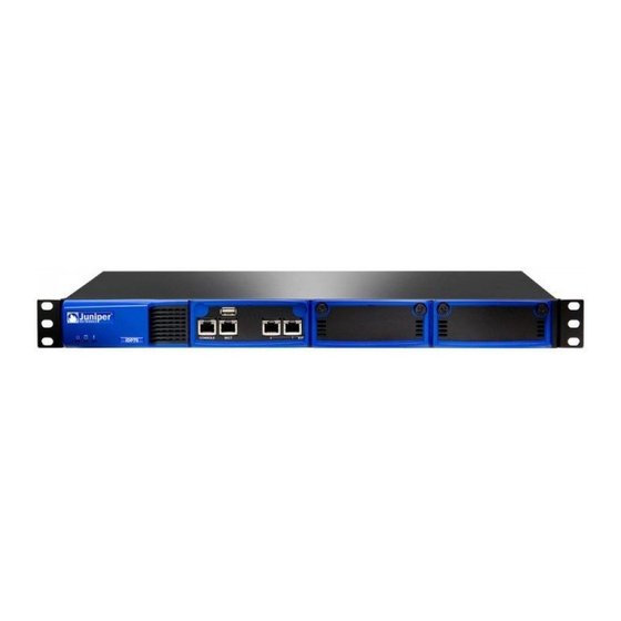
Figure 4 shows the following features: Figure 4: IDP 250 Front Panel IDP 800 Sensor The IDP 800 sensor is optimal for medium-to-large central sites or high-traffic areas. Figure 5 shows the following features: IDP Sensors One console serial port... -
Page 23: Idp 8200 Sensor
Two IOC slots (each IOC containing four gigabit ports) Two built-in copper Ethernet ports (10/100/1000 Mbps) Figure 5: IDP 800 Front Panel IDP 8200 Sensor The IDP 8200 sensor is optimal for large central sites or high-traffic areas. Figure 6... -
Page 24: Traffic Ports (Forwarding Interfaces)
IDP 75, 250, 800, and 8200 Installation Guide Figure 6: IDP 8200 Front Panel Traffic Ports (Forwarding Interfaces) The IDP 75, 250, 800, and 8200 sensors have traffic ports (forwarding interfaces), which are located on the front of each device. Sensors can have a combination of copper and fiber ports. -
Page 25: Normal State
Table 4: NIC State Options Settings Modes Availability NIC bypass Transparent Sensor failure mode only Graceful shutdown External Transparent Sensor failure only bypass unit mode only NICS off All inline Sensor failure modes Graceful shutdown Normal State When the IDP is active and NICs are in the normal state, NICs only pass Layer 2 traffic if in transparent mode and if Layer 2 bypass is enabled. -
Page 26: Nic Bypass And Cable Choices
IDP 75, 250, 800, and 8200 Installation Guide The fiber Ethernet ports are standard interfaces and do not incorporate the integrated bypass feature. Automatic bypass is available for fiber ports through third-party devices. NIC Bypass and Cable Choices When NIC bypass becomes active, it physically connects the pair of forwarding interfaces to each other with a crossover cable. -
Page 27: Peer Port Modulation
Peer Port Modulation After peer port modulation (PPM) is enabled, the sensor deactivates all the interfaces in that virtual router if the link goes down for any of the interfaces in a virtual router. All devices connected to the virtual router will detect a port failure and must be configured to take appropriate action. -
Page 28: Idp Sensor Leds
IDP 75, 250, 800, and 8200 Installation Guide Table 6: IDP Sensor Power Supplies IDP Sensor 800, 8200 IDP Sensor LEDs This section describes the LEDs for the following IDP sensor components: System Status LEDs The IDP 75, 250, 800, and 8200 sensors each have three system status lights on the front panel to indicate power, hard drive activity, and overheating. -
Page 29: Traffic Port Leds
Figure 8: LEDs for Management and HA Ports Table 8: IDP Sensor Management and High Availability Port LED Port LED LINK TX/RX Traffic Port LEDs The IDP 75, 250, 800, and 8200 sensors each have two traffic status LEDs on each traffic port. -
Page 30: Power Supply Leds On Back Panel
IDP 75, 250, 800, and 8200 Installation Guide Table 10: Hard Drive LED Definitions Front Panel LED Hard drive failure (800 and 8200 only) Hard drive activity (800 and 8200 only) Power Supply LEDs on Back Panel The back panel of the sensors provide access to power supplies on the 800 and 8200 sensors only. -
Page 31: Chapter 3 Installing The Sensor
Chapter 3 Installing the Sensor This chapter describes how to install the IDP sensor in an equipment rack. This chapter has the following sections: General Installation Guidelines on page 17 Rack Mounting the IDP Sensor on page 18 Connecting Power on page 20 General Installation Guidelines Observing the following precautions can prevent injuries, equipment failures, and shutdowns. -
Page 32: Rack Mounting The Idp Sensor
The IDP 75 sensor occupies one rack unit (RU) in an equipment rack. One RU is 1.75 inches (44.45 mm) high. The IDP 250, IDP 800 (copper ports), and IDP 8200 sensors occupy two rack units in an equipment rack. -
Page 33: Mounting Using Midmount Brackets
Figure 9: Rail with Hinged Rear Bracket 2. Rotate the hinges on both rails so that they allow the device to slide into the rack. 3. Slide the chassis into a set of rails. CAUTION: Be sure to leave at least two inches of clearance on the sides of each chassis for the cooling air inlet and exhaust ports. -
Page 34: Connecting Power
2. Connect the other end of the power cable to the electrical outlet. 3. (For IDP 800 and 8200 sensors only) Connect the second power cable to the 4. (For IDP 800 and 8200 sensors only) Connect the other end of the second... -
Page 35: Configuring The Idp Sensor
Chapter 4 Configuring the IDP Sensor This chapter describes how to connect to the IDP sensor and configure the device for your network. After you have configured the sensor, you need to connect the device in your network. This chapter has the following sections: Initial Configuration Options on page 21 Connecting to the Sensor on page 22 Connecting Forwarding Interfaces on page 28... -
Page 36: Simple Configuration Values
IDP 75, 250, 800, and 8200 Installation Guide Simple Configuration Values A simple configuration has the following settings and values: Advanced Configuration If you wish to use a sensor mode other than inline transparent or passive sniffer, or if you do not want to use the default options for the other settings, you will have to use the Appliance Configuration Manager. - Page 37 To configure your sensor using the console serial port, do the following: 1. Connect one end of the provided RJ-45 null modem serial cable to the CONSOLE port located on the front of the sensor chassis. 2. Connect the other end of the cable to the serial port of your workstation. 3.
-
Page 38: Using The Management Port To Configure The Sensor
IDP 75, 250, 800, and 8200 Installation Guide 9. Type Y, and then press Enter. 10. Type your default route (gateway address) and press Enter. 11. Type N if the time is correct. If the time is not correct, type Y and follow the Configuration of the management port is now complete. -
Page 39: Connecting Remotely Using The Management Port
2. On a connected computer, open a Web browser. Type https://192.168.1.1. Because the ACM uses an SSL connection, you must type https:// before the NOTE: IP address. 3. Type the default user name (root) and password (abc123). 4. Skip to “Simple or Advanced Configuration Using the Management Port” on page 25. -
Page 40: Quickstart Simple Configuration
IDP 75, 250, 800, and 8200 Installation Guide QuickStart Simple Configuration Table 12 provides the information you need for a simple configuration. Table 12: Information Needed for QuickStart Configuration Field Device Deployment mode Management Interface IP Address Management Interface Netmask Default Route Timezone/ Date/ Time... - Page 41 Table 13: Information Needed for ACM Configuration (continued) Section Configuration Information Networking Speed and duplex settings for IDP sensor interfaces. (Normally, these can be set to auto-detect. With some switches, the speed and duplex settings have to be set manually.) The VLAN interfaces you want to configure.
-
Page 42: Connecting Forwarding Interfaces
IDP 75, 250, 800, and 8200 Installation Guide In proxy-ARP or router mode, if you are using multiple subnets in your protected network, you must configure static routes on the IDP sensor to these subnets. Without static routes, incoming traffic to those subnets can be lost. Alternatively, you can create a static route from the IDP sensor to an internal gateway that contains inbound routes to the protected subnets. -
Page 43: Chapter 5 Adding The Sensor To Nsm
Chapter 5 Adding the Sensor to NSM This chapter describes how to add the IDP sensor to NetScreen-Security Manager (NSM) and push the Recommended policy. When you have completed the steps in this chapter, your IDP sensor will be protecting your network. You must have NSM installed to complete the steps in this chapter. -
Page 44: Figure 12: Begin Add Device Procedure
IDP 75, 250, 800, and 8200 Installation Guide Figure 12: Begin Add Device Procedure 4. On the Security Devices age, click the +button and select Device to open the Figure 13: Add Device Wizard - Device Name 5. Click Next to display the Specify Connection Settings dialog box (Figure 14). Adding Your Sensor to NSM Add Device wizard (Figure 13). -
Page 45: Figure 14: Add Device Wizard - Connection Settings
Figure 14: Add Device Wizard - Connection Settings 6. Enter the following connection information: NOTE: All passwords handled by NetScreen-Security Manager are case-sensitive. a. Enter the IP address of the sensor. b. Enter admin in the Admin User Name box. Enter the password for the admin user name. -
Page 46: Figure 16: Add Device Wizard - Retrieved Settings
IDP 75, 250, 800, and 8200 Installation Guide 7. Verify the SSH key fingerprint to prevent man-in-the-middle attacks: 8. After you have verified the key, click Next to display device information Figure 16: Add Device Wizard - Retrieved Settings 9. Verify that the device type, OS version, device serial number, and device mode 10. -
Page 47: Checking The Status Of Your Sensor
Figure 18: Add Device Wizard - Importing the Device 12. Click Finish to update the sensor with the Juniper Networks Recommended policy. The Job Information dialog shows box the status of the Update Device job. Checking the Status of Your Sensor When the update device job finishes, move the mouse pointer over the device in Device Manager to check the device status. - Page 48 IDP 75, 250, 800, and 8200 Installation Guide Checking the Status of Your Sensor...
-
Page 49: Updating Software On The Sensor
Loading a Sensor Image into NSM To make the sensor software available to NSM: 1. Download firmware image files from Juniper Networks onto the computer running the NSM GUI. 2. In NSM, select Device Manager > Security Devices from the left navigation pane. -
Page 50: Upgrading Sensor Software
To install the new software: 1. Verify that you have SSH enabled for the Management Port (eth0). 2. Download the sensor software from Juniper Networks and copy the file to the 3. Unplug the HA port cable, if one is attached. -
Page 51: Reimaging The Idp Sensor
7. Reboot the device when the script is finished. 8. Type reboot 9. Reconnect the HA cable after upgrading all of the sensors in the cluster. 10. In NSM, right-click the sensor in Device Manager, and then select Adjust OS Version. - Page 52 IDP 75, 250, 800, and 8200 Installation Guide Reimaging the IDP Sensor...
-
Page 53: Chapter 7 Servicing The Device
Replacing a Power Supply (IDP 800, and 8200 Only) The power supplies on the IDP 75 and 250 sensors are in a fixed configuration so you cannot replace them. The IDP 800 sensor has two hot swappable power supplies while the IDP 8200 sensor has three. -
Page 54: Install A Power Supply
6. Attach the other end of the power cord to the power source. Replacing a Hard Drive (IDP 800 and 8200 Only) The IDP 800 and 8200 sensors come with two mirrored hard drives. Both drives are hot-swappable on failure. If one fails, it may be replaced without interrupting the function of the sensor. -
Page 55: Install A Hard Drive
Leave both drives in place until the hard drive array is rebuilt. CAUTION: Removing either drive while the hard drive array is rebuilding can damage the system. Chapter 7: Servicing the Device Replacing a Hard Drive (IDP 800 and 8200 Only) - Page 56 IDP 75, 250, 800, and 8200 Installation Guide Replacing a Hard Drive (IDP 800 and 8200 Only)
-
Page 57: Chapter 8 Advanced Configuration
Chapter 8 Advanced Configuration This chapter describes advanced configuration options and has the following sections: Advanced Deployment Modes on page 43 IDP High Availability Deployment Modes on page 46 Advanced Deployment Modes Most IDP sensors are configured in passive sniffer or transparent mode. However, the IDP 75, 250, and 800 sensors can also be configured in bridge, router, or proxy-ARP mode. -
Page 58: Figure 21: Bridge Mode
IDP 75, 250, 800, and 8200 Installation Guide Figure 21: Bridge Mode Table 14: Advantages and Disadvantages of Bridge Mode Advantages Advanced Deployment Modes Internet Firewall IP 2.2.2.1 IP 1.1.1.1 eth2 No ip address Forwarding Interface IDP Sensor eth0 IP 2.2.2.7 MGT eth3 Interface No IP address... -
Page 59: Router Mode
Router Mode Figure 22 shows a sensor that is configured in bridge mode. Table 15 lists the advantages and disadvantages of bridge mode. Figure 22: Router Mode IDP Sensor eth0 IP 2.2.2.7 MGT Interface Server1 IP 1.1.1.2 GW 1.1.1.1 Table 15: Advantages and Disadvantages of Router Mode Advantages Reliably responds to and prevents attacks Connects IP networks with different... -
Page 60: Proxy-Arp Mode
IDP 75, 250, 800, and 8200 Installation Guide Proxy-ARP Mode Figure 23 shows a sensor that is configured in bridge mode. Table 16 lists the advantages and disadvantages of bridge mode. Figure 23: Proxy-ARP Mode Table 16: Advantages and Disadvantages of Proxy-ARP Mode Advantages IDP High Availability Deployment Modes You must deploy the IDP sensors in bridge, router, transparent, or proxy-ARP... -
Page 61: Appendix A Specifications
It has the following sections: IDP 75 Technical Specifications on page 48 IDP 250 Technical Specifications on page 49 IDP 800 Technical Specifications on page 50 IDP 8200 Technical Specifications on page 51 Safety Compliance on page 52 EMI Compliance on page 52... -
Page 62: Idp 75 Technical Specifications
IDP 75, 250, 800, and 8200 Installation Guide IDP 75 Technical Specifications Tables 17–20 list the physical, AC power, power cord, and environmental technical specifications for the IDP 75 sensor. Table 17: Physical Specifications Specification Height Width Depth Weight Table 18: AC Power Specifications Specification AC input voltage AC input line frequency... -
Page 63: Idp 250 Technical Specifications
IDP 250 Technical Specifications Tables 21–24 list the physical, AC power, power cord, and environmental technical specifications for the IDP 250 sensor. Table 21: Physical Specifications Specification Height Width Depth Weight Table 22: AC Power Specifications Specification AC input voltage AC input line frequency AC input current Table 23: Power Cord Specifications... -
Page 64: Idp 800 Technical Specifications
IDP 75, 250, 800, and 8200 Installation Guide IDP 800 Technical Specifications Tables 25–28 list the physical, AC power, power cord, and environmental technical specifications for the IDP 800 sensor. Table 25: Physical Specifications Specification Height Width Depth Weight Table 26: AC Power Specifications... -
Page 65: Idp 8200 Technical Specifications
IDP 8200 Technical Specifications Tables 29–32 list the physical, AC power, power cord, and environmental technical specifications for the IDP 8200 sensor. Table 29: Physical Specifications Specification Height Width Depth Weight Table 30: AC Power Specifications Specification AC input voltage AC input line frequency AC input current Table 31: Power Cord Specifications... -
Page 66: Safety Compliance
IDP 75, 250, 800, and 8200 Installation Guide Safety Compliance EMI Compliance Immunity Safety Compliance UL 60950, Third Edition — Safety of Information Technology Equipment CSA C2.22 No. 60950, Third Edition — Safety of Information Technology Equipment EN 60950, 2000 — Safety of Information Technology Equipment, including Electrical Business Equipment IEC 60950, Third Edition —... -
Page 67: Index
Index configuration information...26 audience for documentation ... xi bypass mode internal bypass ...11 cable choices ...12 Configurable NICs ...10 conventions defined icons... xi deployment modes advanced...43 high availability ...46 proxy-ARP ...46 drives CD-ROM drives...13 hard drives ...13 EMI compliance specifications...52 high availability deployment modes...46 icons defined notice ... - Page 68 IDP 75, 250, 800, and 8200 Installation Guide Index...
Need help?
Do you have a question about the IDP 800 and is the answer not in the manual?
Questions and answers