Table of Contents
Advertisement
Quick Links
Advertisement
Table of Contents

Subscribe to Our Youtube Channel
Related Manuals for Planmeca Compact i3


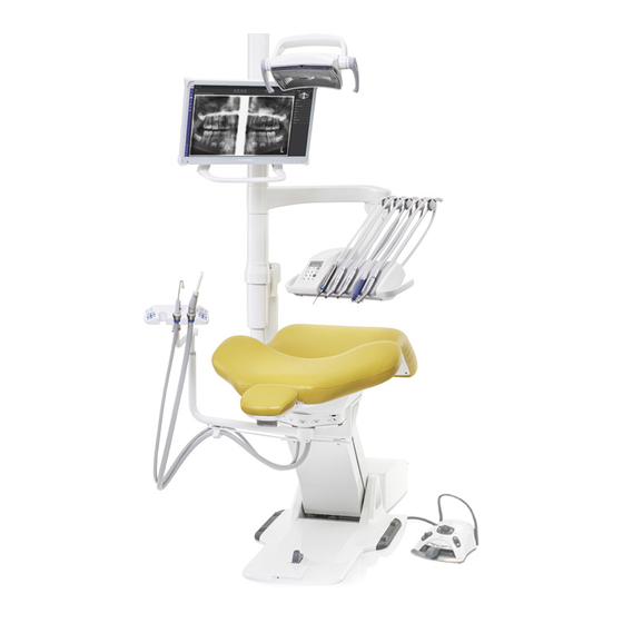
Summary of Contents for Planmeca Compact i3
- Page 1 Planmeca Compact ™ installation manual 30020733 30020733...
- Page 2 IEC 60364 - equipment is used according to the operating instructions. Planmeca pursues a policy of continual product development. Although every effort is made to produce up-to-date product documentation this publication should not be regarded as an infallible guide to current specifications. We reserve the right to make changes without prior notice.
-
Page 3: Table Of Contents
Attaching OP delivery arm to chair....................22 Installing delivery arm cables....................... 28 Installing safety switch........................32 Attaching covers........................... 32 Dental units without operating light and monitor................33 Connecting water and air tubes....................34 Installing Clean water system........................38 Installation manual Planmeca Compact i3... - Page 4 Bleeding spray water system......................90 Final adjustments............................91 17.1 Adjusting friction of OP delivery arm joints................... 91 Switching on dental unit..........................93 Adding service contact details........................94 Resetting yearly maintenance counter..................... 95 PlanID reader settings..........................96 Post-installation checklist..........................97 Planmeca Compact i3 Installation manual...
-
Page 5: Introduction
NOTE The information given in this manual should be taken as a general guide for proper installation of the Planmeca Compact i dental unit. However, in the cases that this information is contradictory to any local or national building regulations, the building regulations must always override this manual. In these cases of contradictory contact your local Planmeca dealer before proceeding with any changes. -
Page 6: Original Manufacturer
Material bank. Before using an instrument, read the instrument’s user’s manual. For a full list of accessories, refer to the Planmeca product price list. 1.3 Original manufacturer Planmeca Oy, Asentajankatu 6, FIN-00880, Helsinki, Finland Phone: +358 20 7795 500, Fax: +358 20 7795 555, http://www.planmeca.com... -
Page 7: Pre-Installation Requirements
If the unit has been stored at temperatures below +10 °C (50 °F) for more than few hours, time must be allowed for the unit to reach the room temperature in its own package, before connecting the dental unit to mains voltage. Installation manual Planmeca Compact i3... -
Page 8: Unit Operating Conditions
The requirements for inlet water are as follows: • Water pressure: 300 - 900 kPa (3 - 9 bar) (44 - 130 psi) Note the differing water pressure requirements for Planmeca WEK and Planmeca ActiveAqua below. • Water flow: At least 4 l/min •... -
Page 9: Suction
2 Pre-installation requirements Dental units with WEK water disinfection system In dental units with Planmeca WEK water disinfection system, the pressure range must be 300 - 600 kPa (3 - 6 bar) (44 - 87 psi). 2.3.3 Suction The static vacuum must be at least 150 mbar. The vacuum pump must be able to produce a flow of at least 550 l/min. -
Page 10: Mains Frequency
2.4.5 External mains switch Mains voltage supply for the dental unit shall be equipped with a separate fixed assembled mains switch according to standard IEC 61058-1:2000 + A1:2001 + A2:2007 complying with isolation distances for 4 kV requirements. Planmeca Compact i3 Installation manual... -
Page 11: Grounding
2.4.9 Cabling for options Some optional features (monitor, Planmeca ProX etc.) require cables between the dental unit and PC or other equipment. Make sure that the needed cables are routed through the service pipe inside the floor. -
Page 12: Network Connection
2 Pre-installation requirements Ethernet cable The Ethernet cable is needed for dental unit / Planmeca Romexis server connection. USB cable The USB cable is needed for USB intraoral camera connection. The repeater cable is routed from the dental unit to the PC. If the distance is over 5 m, another repeater cable must be added. - Page 13 • Romexis server IP address • Romexis communication port The hospital network firewall must be configured to allow connection between the dental unit and Planmeca Romexis. Technical specifications of network connection • Fast Ethernet (IEEE 802.310/100BASE-T) • Minimum requirements: CAT5 cable with RJ45 connector...
-
Page 14: Patient Area
Upgrade of equipment 2.6 Patient area The patient area is 1.5 m (59.1”) in each direction from the dental unit. CAUTION Use only Planmeca specified devices inside the patient area. CAUTION The floor of the patient area must be dry. NOTE Connect only Planmeca specified devices to the dental unit. -
Page 15: Fire Stopping Of Installation Site
1. Dental unit 7. External PC 2. Planmeca monitor 3. Planmeca operating light 4. Foot control. Use only IEC 60601-1 approved power source supplied by Planmeca 5. Tablet 6. Planmeca intraoral scanner 2.7 Fire stopping of installation site NOTE The pipe and cable penetrations must be sealed with fire stopping materials. - Page 16 Fill the floor opening with fire stop sealing compound (e.g. FIREPRO M799 GPG Fire Stop sealing compound). Add waterproof material (e.g. Loctite 5366) above the compound and into the cable pipe. The figure below is an example (installation to a ready-made concrete floor). Planmeca Compact i3 Installation manual...
-
Page 17: Unit Configuration
2. Suction arm with Flexy- 6. Control panel 10. Instrument console with holder hanging-tube instruments 3. Monitor 7. Clean-water bottle 11. Foot control 4. Operating light 8. Instrument console with 12. Foot switch for chair swivel balanced instrument arms Installation manual Planmeca Compact i3... -
Page 18: Attaching Chair To Floor
4. If the floor is made of wood, use the ø8x60 DIN 571 lag screws for the chair attachment. Drill four ø5mm (0.2 in.) holes, 50...55 mm (2.0...2.2 in.) in depth. Do not use expansion anchors with wooden floors. See figure below. Planmeca Compact i3 Installation manual... - Page 19 4 Attaching chair to floor 5. Attach the chair to the floor with four attachment screws. The junction box is attached to the floor later. 6. Attach the protective strips to the chair base. Installation manual Planmeca Compact i3...
-
Page 20: Installing Junction Box
Lift off the cover (4). 2. Unscrew two nuts and detach the clamp from the junction box. Attach the clamp to the chair base with two screws DIN912 M4x8 using a 3 mm Allen key. Planmeca Compact i3 Installation manual... - Page 21 5 Installing junction box 3. Move the junction box into position and attach it to the clamp with two nuts. 4. Loosen two magnetic valve/pressure regulator assembly attachment screws (1) and lift the assembly from its position (2). Installation manual Planmeca Compact i3...
- Page 22 5. Tilt the Main control PCB away upwards (1) and secure it to the clips located on the box frame (2). 6. Attach the junction box to the floor with two screws DIN 7981 4,2 x 25. Planmeca Compact i3 Installation manual...
-
Page 23: Connecting Mains Cable
About this task The chair cables must be connected before the chair can be driven out from the transportation position. Steps 1. Do not remove the jumper from the connector P5 on the Main control PCB yet. Installation manual Planmeca Compact i3... - Page 24 5. Connect the backrest motor potentiometer cable to the connector P17 on the Main control PCB. 6. In case the optional suction element is installed, connect the suction arm and safety extension cable to the connector P6 on the Main control PCB. Planmeca Compact i3 Installation manual...
-
Page 25: Installing Foot Control
The foot control must be connected to the dental unit so that the chair can be driven out from the transportation position. Steps 1. Connect the foot control cable to the connector at the junction box side (1). 2. Switch the power source and the dental unit on. Installation manual Planmeca Compact i3... -
Page 26: Installing Op Delivery Arm
1. Drive the seat to uppermost position. Switch off the dental unit. 2. Unscrew two attachment screws from the lifting mechanism cover plate using a 4 mm Allen key (1). Turn the cover plate downwards (2) and lift it away from the chair (3). Planmeca Compact i3 Installation manual... - Page 27 3. Place the adapter mounting plate to its position (1). Secure the mounting plate to its position with attachment screws ISO 7379 12.9 M10/12x25 (2) and M8x30 DIN 912 (3). 4. Place the adapter cover plate to its position. Installation manual Planmeca Compact i3...
- Page 28 5. Attach the adapter tube to its position with four M8x30 DIN 912 screws using a 5 mm Allen key. Do not tighten the attachment screws yet, the adapter tube position must be adjusted before tightening the screws. Planmeca Compact i3 Installation manual...
- Page 29 6. Attach the adapter tube plate adjustment screws to their positions: set screws M8x16 DIN 916 (1) and set screws M8x12 DIN 913 (2). 7. Adjust the adapter tube position with two screws located at the side of the adapter plate. Installation manual Planmeca Compact i3...
- Page 30 8. Adjust the adapter tube position with the set screws (1 and 2). Tighten the lower attachment screws (3). Tighten the upper attachment screws. 9. The recommended direction of the rotation limiter screw is shown in the figure below. Planmeca Compact i3 Installation manual...
- Page 31 11. Make sure that the joint cover is located so that the openings on the joint cover are towards the chair legrest. Lift the joint cover upwards (1). Secure the joint cover to its position with three set screws M4x6 DIN916 (2). Installation manual Planmeca Compact i3...
-
Page 32: Installing Delivery Arm Cables
12. Slide the pole cover down (1) and secure it to its position with a push rivet (2). 7.2 Installing delivery arm cables Steps 1. Route a cable guide through the vertical post of the delivery arm. Attach the arm cables and tubes to the cable guide. Planmeca Compact i3 Installation manual... - Page 33 3. Route the cables and tubes from the seat (1 and 2) along the lifting mechanism and to the junction box (3). In the lifting mechanism, the cables and tubes are placed on the lower cable duct. Installation manual Planmeca Compact i3...
- Page 34 7 Installing OP delivery arm 4. Secure the cables and tubes as shown in the figure below. Planmeca Compact i3 Installation manual...
- Page 35 OP delivery arm cable to that connector. Connect the other cables to the Main control PCB. All the cables are marked. 6. Attach the chair gounding lead to the grounding terminal located on the chair base. Installation manual Planmeca Compact i3...
-
Page 36: Installing Safety Switch
2. Route the microswitch cable into the seat casting as shown on the figure below. 3. Remove the jumper from the seat microswitch and connect the microswitch cable to that connector. 7.4 Attaching covers Steps 1. Attach the hex spacers to the adapter tube plate. Planmeca Compact i3 Installation manual... -
Page 37: Dental Units Without Operating Light And Monitor
Attach the cover plates with two screws DIN84 M4x8 (3). 7.5 Dental units without operating light and monitor About this task If you are not installing the operating light and / or monitor, a cover plug is inserted to the OP delivery arm opening. Installation manual Planmeca Compact i3... -
Page 38: Connecting Water And Air Tubes
7.6 Connecting water and air tubes About this task Before connecting the air and water tubes make sure that you have correctly identified the floor tubes. Even when they are already labelled it is good to double-check them. Planmeca Compact i3 Installation manual... - Page 39 7 Installing OP delivery arm Steps 1. Connect the water and air inlet tubes to the corresponding angle nipples on the floor (1). Installation manual Planmeca Compact i3...
- Page 40 2. Connect the delivery arm water tube to the nipple at the magnetic valve/ pressure regulator assembly (1). Secure the water tube with the tube clamp (2). Connect the air tube to the nipple in the front of the air pressure regulator (3). Secure the air tube (4). Planmeca Compact i3 Installation manual...
- Page 41 Fold the splash protector (1, 2). 3.b. Remove the lock ring from the water main valve (3). 3.c. Place the splash protector on the water main valve (4). 3.d. Place the lock ring back on the water main valve (5). Installation manual Planmeca Compact i3...
-
Page 42: Installing Clean Water System
8 Installing Clean water system 8 Installing Clean water system Steps 1. Unscrew four arm panel attachment screws and remove the arm panel. Planmeca Compact i3 Installation manual... - Page 43 8 Installing Clean water system 2. Route the cable guide (1) through the delivery arm. Attach the clean- water bottle mount (2) to the adapter tube with two screws DIN 912 M6x16 using a 5 mm Allen key. Installation manual Planmeca Compact i3...
- Page 44 3. Slide the clean-water bottle attachment assembly onto the clean-water bottle mount. 4. Attach the air and water tubes and cables to the cable guide (1) and pull them through the delivery arm to the underside of the vertical arm. Planmeca Compact i3 Installation manual...
- Page 45 / pressure regulator assembly, black air tube going to the instrument console, grey air tube coming from the clean-water bottle. 6. If you are not going to install the vertical arm, attach the arm panel with four arm panel attachment screws. Installation manual Planmeca Compact i3...
- Page 46 8 Installing Clean water system 7. Attach the clean-water bottle (1) to the clean-water bottle attachment assembly. Place the clean-water bottle cover (2) on the attachment assembly. Planmeca Compact i3 Installation manual...
-
Page 47: Installing Vertical Arm
9 Installing vertical arm 9 Installing vertical arm About this task NOTE The monitor and the Planmeca Solanna operating light are optional features. Steps 1. Attach the adapter tube on the OP delivery arm (1). 1.a. Screw the adapter tube into place (2). - Page 48 (2, 3). Tighten the screws using a 3 mm Allen key. The arm shaft divides the inside of the vertical post into two. Route the monitor and operating light cables through the side that is farther away from the horisontal delivery arm. Planmeca Compact i3 Installation manual...
- Page 49 9 Installing vertical arm 4. Attach the arm panel with four arm panel attachment screws. 5. Monitor: Remove the post opening cover from the monitor attachment point on the vertical arm. Installation manual Planmeca Compact i3...
- Page 50 Do not detach the cables. NOTE The monitor arm is installed in the same way with or without the operating light. Only the length of the vertical arm varies in different installation options. Planmeca Compact i3 Installation manual...
- Page 51 The inside of the vertical post is divided into two. Route the cable guide through the side that is farther away from the horisontal delivery arm. 10. Monitor: Route the cable guide and the cables through the vertical post of the delivery arm to the seat. Installation manual Planmeca Compact i3...
- Page 52 12. Attach the vertical arm to the adapter tube of the delivery arm. The monitor arm direction can be altered by rotating the vertical arm. The arm position can be adjusted at intervals of 60°. Lift the arm up and rotate it to the desired position. Planmeca Compact i3 Installation manual...
- Page 53 You can change the limiter pin position by first loosening the adapter ring attachment screws (1) and then rotating the ring (2) until the limiter pin (3) is in the correct position. Finally tighten the attachment screws. Installation manual Planmeca Compact i3...
- Page 54 14. Operating light: Route the cable guide and the ground cable through the vertical arm and the vertical post of the delivery arm to the seat. Planmeca Compact i3 Installation manual...
- Page 55 17. Operating light: The sliding rings (1) and the bearing frame (2) must be located as shown below. Planmeca Solanna Vision: Connect the ethernet cables from the operating light and from the PC to the RJ45 coupler (3).
- Page 56 19. Monitor: Connect the monitor power (1) and the Planmeca Emerald power (2). 20. Monitor: Route the monitor power cable from the junction box to the lifting mechanism and connect it to the power cable coming from the monitor.
-
Page 57: Installing Monitor
The monitor is an optional feature. NOTE The PC connected to the monitor must be: • IEC 60950 approved (CE marked) • Located outside the patient area • Protectively earthed NOTE Be careful not to scratch the screen. Installation manual Planmeca Compact i3... - Page 58 The monitor (1) is attached to the adapter with four attachment screws. Attach the monitor attachment screws (2) tentatively to the monitor using a 3 mm Allen key. Lift the monitor to its position and tighten the attachment screws (3). Planmeca Compact i3 Installation manual...
- Page 59 Attach the grounding lead (2) to the monitor grounding point through the handle opening with a screw (1) and serrated washer (3) using a 3 mm Allen key. Connect the power cable to the monitor connector (4) Connect the HDMI cable to the monitor connector (5). Installation manual Planmeca Compact i3...
- Page 60 10 Installing monitor Push the cover plate (1) to its position and attach it with two attachment screws using a 3 mm Allen key (2). Planmeca Compact i3 Installation manual...
-
Page 61: Adjusting Friction Of Monitor Arm Joint
If needed, you can adjust the rotational friction of the monitor arm joint as shown in the figure below. Adjust the friction of the joint with a 3 mm Allen key. Adjust the two screws equally (1). Loosening the screw increases the friction (2). Installation manual Planmeca Compact i3... - Page 62 Remove the upper cover of the monitor arm joint. Adjust the friction with a 2.5 mm Allen key. Adjust the two screws equally (1). Tightening the screw increases the friction (2). Planmeca Compact i3 Installation manual...
-
Page 63: Chair Swivel
4. To move the seat back to normal movement range lift the rotation limiter pin upwards and move the seat to 30° limit. Then release the locking mechanism by pressing the foot switch and move the seat to desired position. Installation manual Planmeca Compact i3... -
Page 64: Installing Suction Element
The Planmeca Emerald intraoral scanner is an optional feature. 2.a. Route a cable guide through the lifting mechanism. 2.b. Attach the Planmeca Emerald active repeater and power cables (1 and 2) to the cable guide on the junction box side and route the Planmeca Compact i3 Installation manual... - Page 65 With the help of the draw cord, route the suction tube (1) through the lifting mechanism from the opening for the suction element to the junction box. In the lifting mechanism, the suction tube is placed on the upper cable duct (2). Installation manual Planmeca Compact i3...
- Page 66 Connect the assistant syringe cable to the Main control PCB (6). 4.c. Connect the assistant syringe air tube (2) to the air filter/regulator. 4.d. Connect the assistant syringe water tube (2) to the assistant syringe valve. Planmeca Compact i3 Installation manual...
- Page 67 Connect the water tube that goes to the manifold, instrument console and clean-water bottle (DCI) (7) to the water filter/ regulator. 4.h. Connect the air tube that goes to the manifold, instrument console and clean-water bottle (DCI) (7) to the air filter/regulator. Installation manual Planmeca Compact i3...
- Page 68 12 Installing suction element Planmeca Compact i3 Installation manual...
- Page 69 12 Installing suction element NOTE Dental units without city water: Connect the tubes according to the figure below. Installation manual Planmeca Compact i3...
- Page 70 M3x6 DIN 912 screws using a 2.5 mm Allen key (5). 6.f. Secure the Planmeca Emerald active repeater to the repeater holder with a cable tie. Attach it to the USB opening with two attachment screws (6).
- Page 71 Secure the cables coming from the suction arm with a cable tie (9). Make sure that the safety plate can move freely. 7.i. Attach the suction element cover (10) with four M4x10 DIN7991 screws using a 3 mm Allen key (11). Installation manual Planmeca Compact i3...
- Page 72 12 Installing suction element 8. Attach the tube holder to the suction arm with a DIN912 M4x8 screw. Planmeca Compact i3 Installation manual...
-
Page 73: Attaching Suction Tubes And Assistant's Syringe
3. Attach the assistant's syringe (4) to the quick-connector on the underside of the suction element (3). 4. Attach the suction tubes and the tube for the assistant's syringe to the holder on the suction arm. Installation manual Planmeca Compact i3... -
Page 74: Attaching Chair Upholsteries
14 Attaching chair upholsteries 14 Attaching chair upholsteries NOTE The pictures in this section are taken from other Planmeca Compact i dental unit model, but the instructions apply also to Planmeca Compact i3. 14.1 Attaching upholstery support plate Steps 1. Attach the upholstery support plate to the legrest with four sets of sliding part (1), screw ISO7380-1 M6x12 (2) and protective cap (3). -
Page 75: Attaching Seat Upholstery
If the attachment screw does not go into the groove, the screw can be slightly opened by turning it clockwise. Make sure that you have slid the upholstery as far as it goes. Installation manual Planmeca Compact i3... - Page 76 14 Attaching chair upholsteries 3. Tighten the attachment screw by turning it counterclockwise. Planmeca Compact i3 Installation manual...
- Page 77 4. Place the installation plate (white arrow) and the upholstery screw hole cover plate (black arrow) to the seat hole as shown in the figure below. 5. Attach the cover plate to its position with an attachment screw using a 2 mm Allen key. Installation manual Planmeca Compact i3...
- Page 78 14 Attaching chair upholsteries 6. Secure the seat upholstery attachment plates in position with two screws. Planmeca Compact i3 Installation manual...
-
Page 79: Attaching Backrest Upholstery
8. Attach the upholstery to the legrest with two sliding parts and screws. 14.3 Attaching backrest upholstery Steps 1. Bend the upper part of the backrest upholstery firmly from its sides (1) and slide the backrest upholstery upwards so the attachment hook goes Installation manual Planmeca Compact i3... -
Page 80: Attaching Armrests
1. Unscrew the armrest plate attachment screw (1) and remove the plate (2). Attach the armrest plate with an opening (3) to the seat. Place the armrest attachment pin to the opening on the seat in a position shown in Planmeca Compact i3 Installation manual... - Page 81 2. Attach the armrest upholstery (7) to the armrest casting (8) with two 2x50 torx screws (9) using TX 25 key. Grease the armrest inner surfaces with non-toxic vaseline before attaching it to the adapter. Push the armrest to Installation manual Planmeca Compact i3...
-
Page 82: Attaching Headrest
14 Attaching chair upholsteries the adapter at a 45° angle (12, 13) to the seat and then rotate it to the correct direction. 14.5 Attaching headrest Steps 1. Remove the transportation plate from the backrest opening. Planmeca Compact i3 Installation manual... - Page 83 1. Loosen the two holding nuts using the 10 mm fork spanner. 2. Adjust the sliding friction by turning the attachment screws using a screwdriver. Turning the screw counter-clockwise increases the friction. 3. Lock the screw into position with the holding nut. Installation manual Planmeca Compact i3...
-
Page 84: Attaching Tray Table Assembly To Op Delivery Arm Balanced Arm Instrument Console
(2). Hold the plate in position with pliers (3) and tighten the attachment screw (4). The angle of the tray table can be adjusted as follows. Loosen the securing screws (5) and adjust the angle (7) with four adjustment screws (6). Tighten the securing screws. Planmeca Compact i3 Installation manual... -
Page 85: Installing Instruments
Please note that you don’t have to attach instrument hoses (or instrument arms/holders) to all positions. 16.1 Attaching balanced instrument arms Attach the instrument arms (1) to the back side of the instrument console by pushing them firmly into position. Installation manual Planmeca Compact i3... -
Page 86: Attaching Hanging Tube Instrument Holders
Attach the instrument holders to the underside of the instrument console by pushing them firmly into position. The friction of the holders can be adjusted as follows. Remove the console cover and turn the screws on both sides of the console evenly. Planmeca Compact i3 Installation manual... -
Page 87: Attaching Instrument Hoses
16.3 Attaching instrument hoses NOTE Please note that the quick connectors are polarised (not symmetrical) and should be attached with the flat side upwards. 1 Instrument console with balanced instrument arms 2 Instrument console with hanging-tube instruments Installation manual Planmeca Compact i3... -
Page 88: Installing Apex Locator Assembly
Adjust the holders to the desired angles. 16.4 Installing apex locator assembly NOTE The apex locator is not available for Planmeca Compact i Classic. 16.4.1 Instrument console with balanced instrument arms Steps 1. Check that the two DIN912 M3x4 screws on the apex locator housing assembly are loosened before installing. - Page 89 4. Connect the Morita micromotor hose to the apex locator housing assembly and the instrument console, and then connect the micromotor. 5. Test the apex locator function as described in section "Testing apex locator function" on page 87. Installation manual Planmeca Compact i3...
-
Page 90: Instrument Console With Hanging-Tube Instruments
(2) with three screws DIN912 M3x4 (3). 2. Loosely attach two washers (2) and screws DIN7984 M6x12 (3) to the instrument console. Hang the apex locator housing assembly (1) on these screws before tightening the screws. Planmeca Compact i3 Installation manual... -
Page 91: Testing Apex Locator Function
(a1 - a3). NOTE If the Apex locator button is not visible in your control panel's swipe menu, you must add it. For instructions, see your Planmeca dental unit's Organising items on control panel . user's manual, section... - Page 92 The meter may jump when the tester is inserted. If it does, wait for about one second until the meter stabilises and then check the reading. If the reading is 4 or more bars away from 1, the unit will not make an accurate measurement. Contact Planmeca After Sales. Planmeca Compact i3 Installation manual...
- Page 93 If the indicator bars do not appear normally, stop using the device and contact Planmeca After Sales. 6. If you are using the Morita TORX micromotor and the CA-10RC-ENDO 10:1 handpiece with the apex locator, touch the file with the contrary Apex locator electrode.
-
Page 94: Bleeding Spray Water System
6. Tighten the screw so that the water flow stops. 7. Release the foot control pedal and return the instrument to its place in the instrument console. 8. Remove the label attached to the console and attach the console cover. Planmeca Compact i3 Installation manual... -
Page 95: Final Adjustments
2. Rotational friction of console arm 3. Rotational friction of instrument console 4. Lifting friction of console arm Adjust the rotational friction of the console arm column with the adjustment screw (1) located on the column. Installation manual Planmeca Compact i3... - Page 96 Adjust the two screws equally to avoid wearing. Tightening the screws increases the friction. Adjust the lifting friction of the console arm with the 4 mm Allen key. Tightening the screw increases the friction. Planmeca Compact i3 Installation manual...
-
Page 97: Switching On Dental Unit
First, press the on/off switch located at the rear of the unit base to turn the unit on. Then, sign in to the dental unit either with a PlanID card or by selecting a user from the control panel. For instructions, see the Planmeca dental unit's user's manual. Installation manual Planmeca Compact i3... -
Page 98: Adding Service Contact Details
To display special characters, press Alt. Press Alt again to return to the normal view. To save the edited contact detail, press OK. To exit the window without changing the name, press Close. Service contact details window. 6. Press OK to close the Planmeca Compact i3 Installation manual... -
Page 99: Resetting Yearly Maintenance Counter
Confirm yearly maintenance , is for confirming that you have The last item, successfully completed the yearly maintenance. Press > to display the Confirm yearly maintenance window and enter the PIN-code 1701 when prompted. Press OK to reset the yearly maintenance counter. Installation manual Planmeca Compact i3... -
Page 100: Planid Reader Settings
Kr = Korea • AU = Australia • nZ = New Zealand NOTE Do not use PlanID reader outside supported regions. Enter the service mode 602. In this service mode you can enable the PlanID reader. Planmeca Compact i3 Installation manual... -
Page 101: Post-Installation Checklist
Check the additional electrical connections Suction motor control, assistant call etc. Check the connections for optional features Ethernet, USB cable, etc. Perform the needed settings. Refer to dental unit and Planmeca Romexis technical manuals. IP address: ______ Subnet mask: ________ Adjust the internal air and water pressures In the service mode 38 (air 5.0...5.5 bar, water 2.5…2.8 bar). - Page 102 Recalibrate, if necessary. Check the programming function and general operation Check the operation of the emergency switches Backrest, seat and lifting arm. Check the operation of the headrest locking mechanism Solanna operating light Check the mechanical installation Planmeca Compact i3 Installation manual...
- Page 103 Floor attachment screws Electrical safety Check the mains voltage cable and grounding connections Perform the electrical safety measurement according to the local requirements Planmeca Compact i3 Electrical safety measurements Refer to instructions according to IEC 62353 . Technician's Date signature...
- Page 106 Planmeca Oy | Asentajankatu 6 | 00880 Helsinki | Finland tel. +358 20 7795 500 | fax +358 20 7795 555 | sales@planmeca.com | www.planmeca.com...
Need help?
Do you have a question about the Compact i3 and is the answer not in the manual?
Questions and answers