Advertisement
Quick Links
Advertisement

Related Manuals for Planmeca Compact i3


Summary of Contents for Planmeca Compact i3
- Page 1 Planmeca Compact ™ user's manual 30020747...
- Page 2 IEC 60364 - equipment is used according to the operating instructions. Planmeca pursues a policy of continual product development. Although every effort is made to produce up-to-date product documentation this publication should not be regarded as an infallible guide to current specifications. We reserve the right to make changes without prior notice.
- Page 3 USB connectivity.......................... 20 8.6.1 Instrument console.......................20 8.6.2 Suction element......................21 Planmeca Romexis connection....................21 Planmeca intraoral scanner......................22 Planmeca Solanna and Planmeca Solanna Vision operating lights............24 Instrument system............................ 25 10.1 Over-the-Patient (OP) delivery arm....................25 10.2 Instrument console........................26 10.2.1 Instrument console with balanced instrument arms.............
- Page 4 Checking dental unit details........................76 19.1 About this unit..........................76 19.2 Unit type............................77 19.3 Unit serial number........................77 19.4 Unit software version........................77 19.5 Service............................77 19.5.1 Service contact details....................77 19.5.2 Yearly maintenance..................... 77 19.5.3 Storage information......................77 Planmeca Compact i3 User's manual...
- Page 5 Operating dental unit..........................87 21.1 Language............................87 21.2 Timer............................88 21.3 Door open / assistant call......................88 21.4 Planmeca Solanna and Planmeca Solanna Vision operating light..........89 21.4.1 Indicator lights......................90 21.4.2 Switching operating light on/off..................91 21.4.3 Switching composite mode on/off................92 21.4.4 Adjusting intensity of operating light................94...
- Page 6 EMS No Pain scaler....................136 22.8.7 Instrument light......................137 22.9 Planmeca Lumion Plus polymerisation light................137 22.10 Intraoral camera and Planmeca Romexis.................. 138 22.10.1 Intraoral camera placed in instrument console............139 22.10.2 Intraoral camera placed in suction holder..............141 22.11 Planmeca intraoral scanner......................143 22.11.1...
- Page 7 Table of contents 24.4.9 Planmeca Lumion Plus polymerisation light...............162 24.5 Timer settings..........................162 24.6 Planmeca Solanna and Planmeca Solanna Vision operating lights........... 163 24.6.1 Intensity........................163 24.6.2 Colour temperature and brightness................164 24.6.3 Gesture sensor......................166 24.7 Duration of door open / assistant call..................167 24.8...
- Page 8 Positioning of patient, dentist and assistant............... 235 32.3.2 Patient area........................236 32.3.3 Over-the-patient delivery with balanced instrument arms.......... 238 32.4 Planmeca Compact i dental unit water consumption..............239 Certifications............................240 33.1 CE...............................240 33.2 EU Declaration of Conformity for PlanID RFID-reader............... 240 33.3 FCC Class B Notice for PlanID RFID-reader................240...
- Page 9 The Planmeca dental unit is an electrically controlled dental device that consists of a patient chair, delivery arm, dental instruments, operating light and a foot control. The Planmeca dental unit is meant to be used for dental treatment by dental care professionals.
- Page 10 2 Associated documentation 2 Associated documentation This Planmeca dental unit is delivered with the following manuals and diagrams: • User’s manual For dental care professionals. Describes the dental unit and its different parts as well as instructs how to operate and clean the dental unit.
- Page 11 (30007097). The document can be found in the Planmeca Material bank. Before using an instrument, read the instrument’s user’s manual. For a full list of accessories, refer to the Planmeca product price list. User's manual Planmeca Compact i3...
- Page 12 3 Training 3 Training A hands-on user’s training is given in connection with the installation of this device. Planmeca Compact i3 User's manual...
- Page 13 4 Registering your product 4 Registering your product About this task Before you start using your Planmeca product, you must register it to activate the warranty. NOTE As an alternative to navigating to the registration website as described below, you can enter www.planmeca.com/register/...
- Page 14 5 Annual maintenance To guarantee the dental unit’s proper operation, the unit must be checked and serviced by a qualified Planmeca service technician according to the maintenance schedule that has been set for your dental unit. In the annual maintenance, the service technician replaces all parts specified by the maintenance kit.
- Page 15 Warning, hot surface (Standard ISO 7010). Warning: Electricity (Standard ISO 7010). To avoid risk of electric shock, this equipment must only be connected to a supply mains with protective earth. Health hazard (acc. to EC regulation no. 1272/2008). User's manual Planmeca Compact i3...
- Page 16 Radio certification label (Japanese Radio Law). Note that the mains voltage is always present at the mains terminal under the cover, when the unit is switched on. Do NOT open the cover. (Standard IEC 60601-1.) Planmeca Compact i3 User's manual...
- Page 17 7 For your safety 7.1 Safety precautions WARNING No modification of this dental unit is allowed. WARNING Only instruments or equipment approved by Planmeca may be connected to this dental unit. WARNING Do not simultaneously touch the patient and the PC. WARNING Do not simultaneously touch the patient and the USB ports, or any electrical connectors of external instrument modules.
- Page 18 (oxygen content >25%). CAUTION Before using the dental unit, ensure that the instruments have been properly flushed and that the suction tubes as well as the dental unit’s waterlines have been cleaned as instructed in this manual. Planmeca Compact i3 User's manual...
- Page 19 NOTE National regulations concerning the quality of dental water and dental air must be followed when using the Planmeca dental unit. NOTE The water used by the dental unit instruments are to be used for rinsing only.
- Page 20 The safety switches and their functions are described below. 1. Lifting mechanism lower cover An obstruction between the lifting mechanism lower cover and the floor stops downwards chair and backrest movements. Remove the obstruction to resume normal operation. Planmeca Compact i3 User's manual...
- Page 21 • pressing any chair button on the Flexy-holder, • kicking any safety switch, • pushing the foot control pedal or the centre knob in any direction, or by User's manual Planmeca Compact i3...
- Page 22 7 For your safety • pressing the handle of the foot control. Planmeca Compact i3 User's manual...
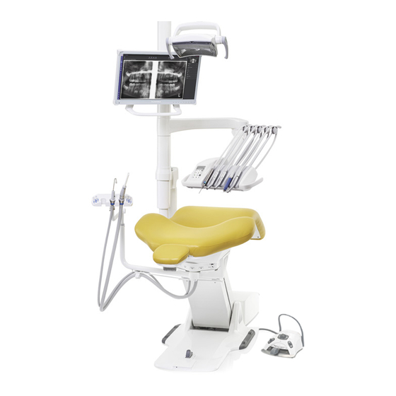
- Page 23 8 Planmeca Compact i3 dental unit 8 Planmeca Compact i3 dental unit 8.1 Unit configuration 1. Patient chair 5. OP delivery arm 9. Tray 2. Suction arm with Flexy- 6. Control panel 10. Instrument console with holder hanging-tube instruments 3. Monitor 7.
- Page 24 8 Planmeca Compact i3 dental unit 8.2 Detachable parts The following detachable components are marked with a manufacturer trademark. Do not perform dental treatment when either or both of these are detached. Balanced instrument arms Headrest The following detachable components are not critical to operation. The user can perform dental treatment even if a wrong, similar part is fitted.
- Page 25 8 Planmeca Compact i3 dental unit Top tray (size 1 and 2) Quick connect tray (size 1 and 2) Armrests Instrument flushing holder (optional) Coarse filter Dentist’s instruments and hoses User's manual Planmeca Compact i3...
- Page 26 8 Planmeca Compact i3 dental unit Suction tubes Assistant’s instruments and hoses Adapter for Luzzani Minibright syringe Adapter for DCI syringe Planmeca Compact i3 User's manual...
- Page 27 8 Planmeca Compact i3 dental unit Foot cover 8.3 Applied parts Applied parts are parts of the dental unit that in normal treatment situations come into contact with the patient. The applied parts of this dental unit include the instruments, the patient chair with upholstery, and the armrests.
- Page 28 8 Planmeca Compact i3 dental unit NOTE Planmeca is not liable for damages caused to the tablet caused by negligence, including but not limited to dropping the tablet on the floor. 8.6 USB connectivity 8.6.1 Instrument console The USB port on the underside of the instrument console offers a USB connection for the dentist’s intraoral camera.
- Page 29 Connect only instruments supplied by Planmeca to the USB port. 8.7 Planmeca Romexis connection The dental unit must be connected to Planmeca Romexis software when you want to use Planmeca Romexis Clinic Management, the intraoral camera, the touchpad functionality, or sign in with a PlanID card.
- Page 30 Romexis connection enabled No symbol Romexis connection disabled The settings for the Planmeca Romexis connection can only be changed by a qualified Planmeca service technician. If, for example, your dental unit configuration includes the Planmeca Romexis Clinic Management module, but the connection is disabled (no symbol displayed on control panel), contact your Planmeca dealer.
- Page 31 8 Planmeca Compact i3 dental unit Planmeca FIT user’s For more information about the intraoral scanner, see manual. User's manual Planmeca Compact i3...
- Page 32 Do not allow the patient to grab the operating light or its arm when getting seated or getting up from the patient chair. You can operate the Planmeca Solanna operating light either from the light itself, or from the dental unit’s control panel or foot control. It also features a “no touch”...
- Page 33 The instrument console can be positioned using the handles on the console. The rotation area of the delivery arm is presented in the illustrations below. The items do not need to be locked into position. The following presents the OP delivery arm with balanced instrument arms. User's manual Planmeca Compact i3...
- Page 34 The console can be equipped with up to five instruments. The leftmost position is reserved for the syringe only. The other instruments can be positioned in any order in the four remaining positions. 1. Syringe Planmeca Compact i3 User's manual...
- Page 35 Note that by positioning the roller higher up, the arm is lighter to bend. 3. Push the roller back in to lock its position NOTE When balancing/adjusting the instrument arms, bear in mind that the instruments shall under no circumstances fall over the patient. User's manual Planmeca Compact i3...
- Page 36 The hose is connected into place by turning the connector locker clockwise, and removed by turning the connector counter-clockwise. Make sure that the flat side of the connector is upward when connecting the quick-connector hose to the dental unit. Planmeca Compact i3 User's manual...
- Page 37 The instrument selection on the instrument console can also be interchanged. The settings of the eight last used instruments are stored in the memory, and are recalled when the instrument is reconnected. User's manual Planmeca Compact i3...
- Page 38 The type or magnitude of the following functions can be programmed: • instrument spray • automatic chip blow • instrument light • instrument speed/power reduction • torque limit • drive mode Bien-Air MX2 micromotors • apical action for Morita TORX micromotors. Planmeca Compact i3 User's manual...
- Page 39 The torque limit for the Bien-Air MCX, Bien-Air MX2 and Morita TORX micromotors can be set to be on or off when the instrument is active (i.e. picked up from the instrument console), see sections "Torque limit" on page User's manual Planmeca Compact i3...
- Page 40 The tray mounting arm is attached to the instrument console with a quick- connector. To remove the tray assembly from the instrument console, pull the ring of the locking mechanism outwards (1) and then pull the tray arm away from its position (2). Planmeca Compact i3 User's manual...
- Page 41 10.5.3 Top tray table The top tray table is placed on top of the instrument console and is available for OP-deliveries with hanging-tube instruments. The maximum load on the top tray table is 2 kilograms (4.4 lbs). User's manual Planmeca Compact i3...
- Page 42 To ensure sterile conditions, extra precaution should be taken to make sure that correct procedures are followed and all the components and tools used (e.g. scissors) are sterile. CAUTION The sterile water bag, nozzle and tubes are disposable and intended for single use only. Planmeca Compact i3 User's manual...
- Page 43 Before using sterile water, you need to set up the sterile water system as described below and edit the instrument spray settings so that sterile water is used (see section "Enabling/disabling sterile water mode" on page 153). 1. Hang the sterile water bag on the holder. User's manual Planmeca Compact i3...
- Page 44 4. Connect the sterile water tube to the sterile water bag by pushing the nozzle firmly into the opening at the bottom of the sterile water bag. 5. Route the other end of the tube to the instrument hose. Planmeca Compact i3 User's manual...
- Page 45 2. Attach the two extension tubes to each other with a tube joint (provided with extension tube pack) (2). This creates the joint extension tube. 3. Attach one end of the joint extension tube to the sterile water tube with nozzle (3). User's manual Planmeca Compact i3...
- Page 46 5. This part (5) goes into the sterile water bag. 6. This part (6) goes into the pump. 10.6.4 Adjusting sterile water flow rate Turn the black knob on the instrument console to adjust the sterile water flow rate. Planmeca Compact i3 User's manual...
- Page 47 The sterile water bag holder that is mounted on the column can be removed from its mount as follows: 1. Loosen the screw on the mount with a 4 mm Allen key. 2. Remove the sterile water bag holder. 3. Tighten the screw. User's manual Planmeca Compact i3...
- Page 48 NOTE Make sure that there is nothing under the suction arm when driving the chair down. Remove the obstruction to resume normal operation. 11.2 Flexy-holder The suction handpieces are placed in the Flexy-holder. Planmeca Compact i3 User's manual...
- Page 49 When the suction tubes are placed in all three Flexy-holder openings, the assistant's syringe and one other instrument (intraoral scanner, USB intraoral camera or polymerisation light) can be placed in the supplementary holders. User's manual Planmeca Compact i3...
- Page 50 The suction tube, instrument and supplementary holders can be removed from the Flexy-holder, for example for cleaning. Remove the suction tube holder by pulling it downward from the Flexy- holder. To replace it, push it firmly into its place. Planmeca Compact i3 User's manual...
- Page 51 To replace it, push it firmly into its place. Remove the instrument holder by squeezing it from the bottom and at the same time lifting it upward. To replace it, squeeze the holder and insert it into its place. User's manual Planmeca Compact i3...
- Page 52 For instructions, see section "Manual suction cleaning" on page 181. 2. Detach the securing ring (1) from the suction tube. NOTE You can grease the securing ring with non-toxic vaseline to make it easier to remove. Planmeca Compact i3 User's manual...
- Page 53 11 Suction system 3. Remove the suction tube (2) from the suction tube connector. 4. Replace the suction tubes in the reverse order. User's manual Planmeca Compact i3...
- Page 54 12.1 Patient recognition A sensor in the patient chair recognises if there is a patient in the chair and forwards information about this to Planmeca Romexis Clinic Management software. When a patient is in the chair, a Patient icon is displayed on the control panel.
- Page 55 1 and 3 presented below. The armrest can be removed when it is in position 2. Surgical armrest As an option, a surgical armrest is available. The patient’s arm can be strapped to the armrest when, for example, infusing saline solution. User's manual Planmeca Compact i3...
- Page 56 (2). The surgical armrest is removed in the same way as the standard armrest. 12.4 Manual headrest 12.4.1 Adjusting height of headrest The height of the headrest can be adjusted by sliding it manually. Planmeca Compact i3 User's manual...
- Page 57 When adjusting, the headrest should be supported by hand. 12.4.3 Adjusting headrest for children or short patients The headrest can be turned around and repositioned for better head support for children or short patients. User's manual Planmeca Compact i3...
- Page 58 12 Patient chair Pull the headrest out. Turn it around so that the cushion faces backward and push the headrest back into the chair. Turn the cushion around (180° counter-clockwise). Planmeca Compact i3 User's manual...
- Page 59 The headrest is now repositioned. To adjust the angle of the headrest, press the locking bar. Manually set the headrest into the required position and release the bar. When adjusting, support the headrest with your other hand. User's manual Planmeca Compact i3...
- Page 60 You can operate the control panel by touching it with your finger or with a soft stylus. The display is generally medical glove touch capable, but some glove types have limited functionality. The control panel shows information related to the current operation and changes accordingly. Planmeca Compact i3 User's manual...
- Page 61 The touchpad function requires that the dental unit is connected to Planmeca Romexis software. The software version must be 4.1 or later. If there is no Planmeca Romexis connection, the function is disabled and the Touchpad button is grey. Using control panel as computer mouse In the the touchpad-view, press Touchpad to open the mouse-view on the control panel.
- Page 62 ^ are displayed. You will automatically return to the normal view when you enter one of the letters. To return to the normal view without entering a letter, press the symbol again. Planmeca Compact i3 User's manual...
- Page 63 Planmeca Solanna Vision video streaming on/off • start/stop Planmeca Solanna Vision video recording • capture an image with the Planmeca Solanna Vision camera • open/close the Planmeca Solanna Vision window. For more information, contact your Planmeca dealer. User's manual...
- Page 64 The foot control is a precision instrument. Do not stand on or apply unnecessary force to the foot control and its knobs. CAUTION Do not use the foot control in areas where liquids are likely to be present on the floor. Planmeca Compact i3 User's manual...
- Page 65 NOTE If you want to change from a standard pedal to the wide pedal, or vice versa, contact your Planmeca dealer. The two foot control pedals function differently. For example, to increase the instrument speed, you must push the standard pedal horizontally, either to the left or to the right.
- Page 66 14.3.2 Left-side and right-side knob functions Action Function Left-side knob up Can be configured by a Planmeca service technician. Default function: Operating light on/off Left-side knob down Can be configured for a selection of instruments by a Planmeca service technician.
- Page 67 Pedal left Move upward in the list of scan type selection tools Pedal right Move downward in the list of scan type selection tools Pedal down, short activation Start scanning Pedal down, long activation Take image User's manual Planmeca Compact i3...
- Page 68 The on/off switch (1) is located on the unit base. Press the switch to turn the unit on. Press the switch again to turn the unit off. When the unit is switched on, the on/off switch light is on. Planmeca Compact i3 User's manual...
- Page 69 16.1 Signing in NOTE The sign in method depends on the dental unit’s configuration. For more information on the configuration, or for changing it, contact your Planmeca dealer. NOTE Before you can sign in with a PlanID card, you must assign a PlanID card to your user profile.
- Page 70 It is also possible to sign in to the dental unit as a guest user by pressing the Sign in window. Guest user button in the Once you have signed in, the treatment window opens and you can start using the dental unit with your own personal settings. Planmeca Compact i3 User's manual...
- Page 71 16 Signing in and out Factory settings are loaded for guest users every time they sign in. 16.2 Signing out Steps 1. In the top left corner of the treatment window, press Sign out. User's manual Planmeca Compact i3...
- Page 72 When you sign in to the dental unit, you can start using the unit with your own personal settings. Depending on the dental unit configuration, the settings are either stored in the dental unit or in Planmeca Romexis software. For more information, contact your Planmeca dealer.
- Page 73 For information on how to edit the user settings, see section "Editing user settings" on page 66. 17.3 Deleting user Steps Sign in window, press Edit next to the user that you want to delete. 1. In the User's manual Planmeca Compact i3...
- Page 74 Sign in window. Your user name is deleted from the user list in the NOTE The user profile optionally saved in Planmeca Romexis is not deleted. For more information, contact your Planmeca dealer. 17.4 Editing user settings User settings window. There are two...
- Page 75 "Language" on page 87. 17.4.1 Editing user name Steps User settings window, press Edit next to First name . 1. In the Set first name window opens. User's manual Planmeca Compact i3...
- Page 76 6. When you have entered your last name, press OK to save the last name User settings window. and return to the Set last name window without saving the user Pressing Close exits the name. Planmeca Compact i3 User's manual...
- Page 77 You can scroll the list of languages either from the list itself or from the scroll bar to the right. When you press a language to select it, you will automatically return to User settings window. User's manual Planmeca Compact i3...
- Page 78 User settings window. OK in the 17.4.3 Editing colour theme Steps User settings window, press Edit next to Color theme . 1. In the Program - Theme window opens. Planmeca Compact i3 User's manual...
- Page 79 Sign in window. affect your user name or your position on the user list in the NOTE This reset only applies to settings stored in the dental unit. For more information, contact your Planmeca dealer. User's manual Planmeca Compact i3...
- Page 80 In the want to reset. Sign in to the dental unit and press Program > User settings. User settings window opens. 2. Press Reset. A confirmation message is displayed. 3. Confirm the reset by pressing OK. Planmeca Compact i3 User's manual...
- Page 81 These will be shown in the dental unit as your first and last name. NOTE If you have stored a picture of yourself in Planmeca Romexis software, the User settings window and in the picture will show in the dental unit’s Welcome-message that is displayed when you sign in to the dental unit.
- Page 82 4. Enter your Romexis username and save the changes by pressing OK. Add User The username must be the same that you entered in the window in Planmeca Romexis. Only letters A-Z and a-z, period (.), hyphen (-), underscore (_) and the “at” sign (@) are allowed.
- Page 83 Assign PlanID tag window by pressing OK. 6. Close the User settings window by pressing OK. 7. Close the Results Your PlanID card has now been assigned to you and you have been signed in to the dental unit. User's manual Planmeca Compact i3...
- Page 84 2. Press About this unit. About this unit window opens. NOTE The following is an example only and does not necessarily portray the actual situation. > means that more information can be opened to a new window. Planmeca Compact i3 User's manual...
- Page 85 • how many days are left until the next yearly maintenance. The last item, Confirm yearly maintenance , is for qualified Planmeca service technicians only. 19.5.3 Storage information Storage information contains details on the control panel SD card.
- Page 86 GUI Diagnostics shows the current hardware revision of the control panel and also contains tools for finding possible errors in the touch display. CAUTION GUI diagnostics is only meant to be used by a qualified Planmeca service technician. 19.5.5 PlanID...
- Page 87 Network mask • Gateway CAUTION The network settings may only be edited by a qualified Planmeca service technician. 19.7 Message history Message history displays help and error messages when you press >. For information on how to use the message log, see section "Viewing help and error message history"...
- Page 88 When driving the chair near the upper limit, make sure that the console arm does not press or hit the patient. CAUTION When driving the backrest up, make sure that the patient’s hand or arm does not get squeezed between the armrest and the backrest. Planmeca Compact i3 User's manual...
- Page 89 To drive the backrest up, press the Backrest up button until the chair reaches the required position. To drive the chair up, press the Chair up button until the chair reaches the required position. User's manual Planmeca Compact i3...
- Page 90 When the chair reaches the desired position, release the centre knob. You can steer the chair only in one direction at a time. 20.3 Automatic operation 20.3.1 Overview Automatic chair positions can be stored into memory. Planmeca Compact i3 User's manual...
- Page 91 If the chair does not move downward and H 3 is displayed, remove the obstruction. 20.3.2 Extended vs. traditional view User settings window, select whether you want to view the automatic In the positions in a traditional or an extended view. • Extended view User's manual Planmeca Compact i3...
- Page 92 For information on how to adjust the preprogrammed automatic positions, see section "Extended view" on page 149. When the chair is in an automatic position, the current position is displayed on the Chair positions button in the main window. Planmeca Compact i3 User's manual...
- Page 93 When the chair stops in the entry/exit position, the indicator light remains on. When you press Entry/exit position again, the chair will return to the previous working position. The indicator light flashes throughout the movement. User's manual Planmeca Compact i3...
- Page 94 The chair movement stops also when any of the safety switches are activated. The chair can be driven normally after the possible obstruction has been removed. For information on the safety switches, see section "Safety switches" on page 12. Planmeca Compact i3 User's manual...
- Page 95 Italian • Swedish • Hungarian • Czech • Danish • Norwegian • Russian • Japanese • Polish • Traditional Chinese • Simplified Chinese • Romanian • Arabic • Dutch • Portuguese • Turkish • Greek User's manual Planmeca Compact i3...
- Page 96 If you have installed a door opening device or assistant call, you may activate these from the control panel or the foot control. NOTE Only one of these functions can be enabled at a time. To change the enabled function, contact your Planmeca dealer. Planmeca Compact i3 User's manual...
- Page 97 The duration of the signal can be programmed, see section "Duration of door open / assistant call" on page 167. 21.4 Planmeca Solanna and Planmeca Solanna Vision operating light CAUTION Do not allow the patient to grab the operating light or its arm when getting seated or getting up from the patient chair.
- Page 98 The operating light is on and the colour temperature is neutral. Light blue The operating light is on and the colour temperature is cool. Peach The operating light is on and the colour temperature is warm. Planmeca Compact i3 User's manual...
- Page 99 Briefly press the handle button on either handle to switch the light on. Press the handle button a second time to switch the light off. You will hear a clicking sound when you press the button. User's manual Planmeca Compact i3...
- Page 100 NOTE The foot control can also be configured so that the operating light is switched on/off when you push the right-side knob up. Contact your Planmeca dealer. 21.4.3 Switching composite mode on/off The composite mode allows you to work with composite materials with minimal risk of pre-polymerisation caused by the operating light.
- Page 101 From dental unit When you switch the composite mode on, the indicator light on the Composite mode button is lit. Control panel: Press Composite mode to switch the operating light’s composite mode on or off. User's manual Planmeca Compact i3...
- Page 102 The operating light intensity can also be programmed, see section "Planmeca Solanna and Planmeca Solanna Vision operating lights" on page 163. NOTE The operating light intensity will decrease to 30% of the maximum intensity when the chair is moving.
- Page 103 NOTE The foot control can also be configured so that the intensity is adjusted when you push and hold the right-side knob up. Contact your Planmeca dealer. After one second, the intensity will increase until you release the button/ knob. When you press and hold the button/knob again, the intensity will start to decrease.
- Page 104 21 Operating dental unit The operating light intensity can also be programmed, see section "Planmeca Solanna and Planmeca Solanna Vision operating lights" on page 163. From operating light From one handle Press and hold the handle button on either handle to adjust the intensity of the operating light.
- Page 105 Contact your Planmeca dealer. NOTE The foot control can be configured so that the intensity is adjusted when you push and hold the left-side or the right-side knob up. Contact your Planmeca dealer. 21.4.6 Changing light tone of operating light The white light tone of the operating light can be warm, neutral or cool.
- Page 106 Planmeca Romexis software version 6.0 or later must be installed. When Planmeca Romexis is running, the camera is continuously connected to the software. • Planmeca Romexis and the dental unit have been paired by a Planmeca service technician. • The connection between Planmeca Romexis and the dental unit has been enabled by a Planmeca service technician.
- Page 107 Solanna Vision window in the dental unit. This does not open the To switch full screen mode on/off, press the f key on the Planmeca Romexis keyboard. To switch low latency mode on/off, press the l key on the Planmeca Romexis keyboard 21.5.1.2 Activating camera from dental unit...
- Page 108 Solanna Vision window can be configured Planmeca dental unit: Planmeca Compact i: The Control panel on Flexy- to be opened by pressing the Flexy button, contact your Planmeca holder dealer. Solanna Vision window can be configured Planmeca dental unit: Foot...
- Page 109 21.5.2.2 Adjusting video settings Steps Solanna Vision window in the dental unit. 1. Open the For instructions, see section "Activating camera from dental unit" on page 99. Solanna Vision window, press Settings. 2. In the User's manual Planmeca Compact i3...
- Page 110 21.5.3 Switching video streaming on/off Solanna When video streaming is on, the live video stream is played in the Vision window in Planmeca Romexis. Solanna Vision window in Planmeca When you turn streaming off, the Romexis closes. The window opens again when you turn streaming on.
- Page 111 When the Planmeca Romexis keyboard to pause streaming. Press Space again to resume streaming. Planmeca dental unit: When video streaming is on, the camera indicator light on the Solanna Vision button in the main window indicates that streaming is going on.
- Page 112 Solanna Vision button in the main window blinks to indicate that recording is going on. Planmeca Romexis: When recording is going on, a red recording icon in the Solanna Vision window indicates that recording is going top left corner of the...
- Page 113 21 Operating dental unit How to capture image Interface Action Planmeca dental unit: Planmeca Compact i: The dental unit can be configured so that an Control panel on Flexy- image is captured when you press the Flexy button, contact your holder Planmeca dealer.
- Page 114 Therefore, an alternative instrument logic can be taken into use for four-handed dentistry. Please contact your Planmeca dealer. In intelligent four-handed dentistry one instrument can be left waiting in a queue so that it is ready for use when the dentist returns the active instrument to the instrument console.
- Page 115 To stop the instrument, allow the pedal to return to the rest position. CAUTION Ensure that the pedal is in rest position when you activate the instrument. NOTE The speed/power level depends on the instrument. User's manual Planmeca Compact i3...
- Page 116 NOTE The foot control can be configured so that the micromotor’s speed or power is limited when you push the left-side knob down. Contact your Planmeca dealer. NOTE Check the indicator light on the control panel to verify that pushing the left- side knob down activates the correct function.
- Page 117 Push the pedal again to switch on the air spray. You will hear one short signal tone. Push the pedal a third time to switch off the instrument spray. You will hear one long signal tone. User's manual Planmeca Compact i3...
- Page 118 NOTE The foot control can also be configured so that you push the left-side knob down to select a different spray setting. Contact your Planmeca dealer. NOTE Check the indicator light on the control panel to verify that pushing the left- side knob down activates the correct function.
- Page 119 NOTE The foot control can be configured so that you push the left-side knob down to switch the instrument light on/off. Contact your Planmeca dealer. NOTE Check the indicator light on the control panel to verify that pushing the left- side knob down activates the correct function.
- Page 120 Only the drive mode Auto stop is available for the Bien-Air MCX micromotor. NOTE The foot control can be configured so that you push the left-side knob down to enable/disable the torque function. Contact your Planmeca dealer. NOTE Check the indicator light on the control panel to verify that pushing the left- side knob down activates the correct function.
- Page 121 The green indicator light means that the RPM limit is on. Press RPM limit again to switch the rpm limit off. 22.4 Bien-Air MX2 micromotor Besides the basic micromotor functions, the Bien-Air MX2 micromotor has some additional features. These are described below. User's manual Planmeca Compact i3...
- Page 122 The foot control can be configured so that you push the left-side knob down either to enable/disable the torque function or to select the drive mode. Contact your Planmeca dealer. NOTE Check the indicator light and the drive mode symbol on the control panel to verify that pushing the left-side knob down activates the correct function.
- Page 123 The following table presents the default preset settings for the Bien-Air MX2 micromotor. These presets can be modified, see section "Modifying preset values" on page 156. The tolerance for RPM and torque values is +/- 5%. User's manual Planmeca Compact i3...
- Page 124 NOTE The foot control can be configured so that you push the left-side knob down to enable/disable the torque function. Contact your Planmeca dealer. NOTE Check the indicator light on the control panel to verify that pushing the left- side knob down activates the correct function.
- Page 125 When the apical action autoforward is selected and the flash bar is reached, the micromotor will rotate counter-clockwise (reverse) until it has reversed three segments on the apex meter and then return to clockwise rotation. User's manual Planmeca Compact i3...
- Page 126 - t3 are torque presets where the torque limit can be enabled. Presets a1 - a3 can only be used with the Morita CA-10RC-ENDO 10:1 endo-contra handpiece. This handpiece must not be used with other presets than a1 - a3. Planmeca Compact i3 User's manual...
- Page 127 Default: On Default: On Rotation Forward/ Forward/ Forward/ Forward/ Forward/ Reverse Reverse Reverse Reverse Reverse Default: Default: Default: Default: Default: Forward Forward Forward Forward Forward rotation rotation rotation rotation rotation User's manual Planmeca Compact i3...
- Page 128 CA-10RC-ENDO 10:1 handpiece and for hand files. The apex locator can be operated from the dental unit's control panel. More detailed information on how to measure the root canal can be found in the operation instructions provided by Morita. Planmeca Compact i3 User's manual...
- Page 129 CAUTION Before using the Morita Root ZX mini U apex locator, read the documentation provided by Morita. 1. Probe cord The probe cord is plugged into the jack on the back of the instrument console. User's manual Planmeca Compact i3...
- Page 130 Before treating a patient: • Make sure that the probe cord is securely plugged into the jack on the back of the instrument console. Planmeca Compact i dental unit with hanging-tube instruments Planmeca Compact i3 User's manual...
- Page 131 22 Operating instruments Planmeca Compact i dental unit with balanced instrument arms • Check that the file holder and contrary electrode are properly connected to the probe cord. • If you are using a hand file with the apex locator, touch the metal part of the file holder with the contrary electrode.
- Page 132 22 Operating instruments If the indicator bars do not appear normally, stop using the device and contact your Planmeca dealer. 22.6.2 Using apex locator The Morita Root ZX mini U apex locator can be used both with hand files and with the Morita TORX micromotor and the CA-10RC-ENDO 10:1 handpiece.
- Page 133 2 on the meter scale. For the 5 first bars, the beep signal is slow, after which the beep signal becomes fast, and finally becomes continuous when it reaches the flash bar. 1 Slow beep signal 2 Fast beep signal 3 Continuous signal User's manual Planmeca Compact i3...
- Page 134 1. Continuous signal 22.6.3 Testing apex locator function About this task The apex locator function must be tested weekly. NOTE While the test is going on, the control panel is locked. Planmeca Compact i3 User's manual...
- Page 135 The meter may jump when the tester is inserted. If it does, wait for about one second until the meter stabilises and then check the reading. If the reading is 4 or more bars away from 1, the unit will not make an accurate measurement. Contact your Planmeca dealer. User's manual Planmeca Compact i3...
- Page 136 1 3 bars above 1 2 3 bars below 1 22.7 Turbine The turbines supplied by Planmeca have a built-in backflow prevention system, which protects the water used in the instrument from contamination. CAUTION A power cut will shut down the software-controlled backflow prevention system.
- Page 137 Quickstart to enable/disable the quickstart. NOTE The foot control can be configured so that you push the left-side knob down to enable/disable the quickstart. Contact your Planmeca dealer. NOTE Check the indicator light on the control panel to verify that pushing the left- side knob down activates the correct function.
- Page 138 NOTE The foot control can also be configured so that you push the left-side knob down to select a different spray setting. Contact your Planmeca dealer. NOTE Check the indicator light on the control panel to verify that pushing the left- side knob down activates the correct function.
- Page 139 The instrument spray operated with the foot control can be disabled in the service mode, in which case you can switch the spray on and off only from the control panel. Contact your Planmeca dealer. 22.7.4 Speed/power limit When the turbine’s speed/power limit is on and the preset value is, for example, 50%, the foot control pedal movement controls the speed/power between 5 - 50% instead of the normal range of 5 - 100%.
- Page 140 NOTE The foot control can be configured so that you push the left-side knob down to switch the automatic chip blow on/off. Contact your Planmeca dealer. NOTE Check the indicator light on the control panel to verify that pushing the left- side knob down activates the correct function.
- Page 141 NOTE The foot control can be configured so that you push the left-side knob down to switch the instrument light on/off. Contact your Planmeca dealer. NOTE Check the indicator light on the control panel to verify that pushing the left- side knob down activates the correct function.
- Page 142 Push the pedal again to switch on water 2. You will hear one short signal tone. Push the pedal a third time to switch off the instrument spray. You will hear one long signal tone. Planmeca Compact i3 User's manual...
- Page 143 NOTE The foot control can also be configured so that you push the left-side knob down to select a different spray setting. Contact your Planmeca dealer. NOTE Check the indicator light on the control panel to verify that pushing the left- side knob down activates the correct function.
- Page 144 22 Operating instruments NOTE The foot control can be configured so that you push the left-side knob down to change the scaler mode. Contact your Planmeca dealer. NOTE Check the scaler mode symbol on the control panel to verify that pushing the left-side knob down activates the correct function.
- Page 145 NOTE The foot control can be configured so that you push the left-side knob down to switch the instrument light on/off. Contact your Planmeca dealer. NOTE Check the indicator light on the control panel to verify that pushing the left- side knob down activates the correct function.
- Page 146 5 seconds. The progress of the polymerisation cycle is displayed on the control panel. Independent mode The Planmeca Lumion Plus polymerisation light can also be operated in the independent mode. The independent mode is typically used when the Planmeca Lumion Plus polymerisation light is attached to the assistant...
- Page 147 After you have saved the images Once you have saved the images, you can browse through them in the Planmeca Romexis Image browser. Press the Done button at the bottom of the intraoral camera window in Planmeca Romexis to move to the Image Planmeca browser.
- Page 148 • you will hear a short sound signal, • the Planmeca Romexis intraoral camera view is displayed on the monitor, • the text “Intraoral camera active” is displayed on the dental unit's control panel.
- Page 149 Starting intraoral camera Before you turn on the intraoral camera, first select the patient and the 2D module in Planmeca Romexis. Then, start the camera from the dental unit. 1. Pick up the camera from the suction holder (Flexy-holder). 2. Activate the intraoral camera with the foot control by pushing the right- side knob up (factory default setting).
- Page 150 Saving image A frozen image can be saved from the dental unit, the handpiece and Planmeca Romexis. From the handpiece you can save an image also without freezing the image first. A long sound signal indicates that an image is saved. When the image is being saved, the indicator light on the handpiece blinks orange.
- Page 151 Activating instrument view The foot control can be configured so that the Planmeca intraoral scanner is activated when you first pick up the scanner from the Flexy-holder and then push the left-side or the right-side knob up. Contact your Planmeca dealer.
- Page 152 Push the left-side knob down to generate a model of the scanned area. Selecting scanning mode To move upward in the list of scan type selection tools in the Planmeca Romexis menu on the monitor, push the foot control pedal to the left.
- Page 153 In addition to the instructions below, the suction can also be configured so that it is started/stopped by pushing the foot control’s left-side or right-side knob up, or by pressing the Flexy button. Contact your Planmeca dealer. NOTE If you have stopped the suction from the foot control or the Flexy button while the suction handpiece was in your hand, the suction will start for a while when you return the handpiece to the suction holder.
- Page 154 You can stop the suction temporarily by “straightening” the suction handpiece with your thumb and forefinger. If you temporarily put the suction handpiece down during dental treatment, the suction will automatically stop as the force of the suction will straighten the handpiece. Planmeca Compact i3 User's manual...
- Page 155 (right or left) the parameter changes quickly. 5. Press OK to store the new setting into memory. The pop-up window closes. When you press Program, you will also see the following symbols on the control panel: service mode User's manual Planmeca Compact i3...
- Page 156 4. Press OK to confirm the new order. If you do not wish to save the new order, press Close. Planmeca Compact i3 User's manual...
- Page 157 The chair height cannot be programmed near the upper limit. The help code H 8 is displayed if the chair position is not allowed. When needed, the upper limit can be altered. Contact your Planmeca dealer. 24.3.1 Extended view About this task...
- Page 158 Close. 8. Press OK to confirm that you want to save the current position as an automatic position. If you do not wish to save the position as an automatic position, press Close. Planmeca Compact i3 User's manual...
- Page 159 24.4.1 Instrument speed/power limit About this task NOTE The instrument speed/power limit does not affect the air driven instruments for which quickstart has been selected. Steps 1. Activate the instrument. 2. Press Program. User's manual Planmeca Compact i3...
- Page 160 The adjustment step is 1 in the value range 0 - 35% and 5 in the value range 35 - 100%. 5. Press OK. The pop-up window closes and the new values are displayed on the control panel. Planmeca Compact i3 User's manual...
- Page 161 24 Programming 24.4.3 Enabling/disabling sterile water mode About this task If the dental unit is equipped with the Planmeca Sterile water system or Steripump, enable/disable the sterile water mode as described below. NOTE The flow rates for sterile water can not be adjusted by the user.
- Page 162 The pop-up window closes and the new values are displayed on the control panel. 24.4.6 Bien-Air MCX micromotor About this task Changing the instrument spray, chip blow and LED values for the Bien-Air MCX micromotor follows the normal programming pattern. For more Planmeca Compact i3 User's manual...
- Page 163 1 000 (e.g. 11 000, 12 000 etc..) 20 000 - 38 000 2 000 (e.g. 22 000, 24 000 etc..) 6. Press OK. The pop-up window closes and the new value is displayed on the control panel. User's manual Planmeca Compact i3...
- Page 164 Toggle between the drive modes by pressing the current drive mode - button. The modes are: Auto stop The micromotor stops when the torque limit is reached. Auto reverse When the torque limit is reached the micromotor will operate counter-clockwise. Planmeca Compact i3 User's manual...
- Page 165 The pop-up window closes and the new value is displayed on the control panel. 8. Press Program. 9. Press Torque to adjust the torque limit rate. A pop-up window opens. 10. Adjust the torque limit rate. The adjustment range is 10% - 95%. User's manual Planmeca Compact i3...
- Page 166 When you have modified the settings of a preset, but have not saved them, a dash (–) replaces the preset number on the control panel. The procedure for saving the modified preset settings is explained in section "Saving modified preset values" on page 159. Planmeca Compact i3 User's manual...
- Page 167 2. All presets: Adjust the RPM limit. 2.a. Press Program. 2.b. Press RPM limit. A pop-up window opens. 2.c. Set the RPM limit. 2.d. Press OK. The pop-up window closes and the new value is displayed on the control panel. User's manual Planmeca Compact i3...
- Page 168 The amount of water and air can also be programmed. 9. Presets 1 - 3 and t1 - t3 only: Press Instrument light to switch the instrument light on or off. Planmeca Compact i3 User's manual...
- Page 169 3. Press OK to confirm that you want to save the new settings. If you do not want to save the new settings, press Cancel. The preset window is closed. The settings are stored in the dental unit when you return the instrument to its holder. User's manual Planmeca Compact i3...
- Page 170 24 Programming 24.4.9 Planmeca Lumion Plus polymerisation light About this task NOTE The duration of the polymerisation cycle can be programmed only for the Planmeca Lumion Plus polymerisation light. Steps 1. Activate the instrument. 2. Press Program. 3. Press Polymerisation cycle.
- Page 171 24 Programming 5. Press OK. The pop-up window closes. 24.6 Planmeca Solanna and Planmeca Solanna Vision operating lights 24.6.1 Intensity About this task NOTE The light intensity can also be adjusted from the operating light, see sections "Adjusting intensity of operating light" on page 94 and "Adjusting intensity of operating light in composite mode"...
- Page 172 The pop-up window closes and the new values are displayed on the control panel. 24.6.2 Colour temperature and brightness About this task NOTE The colour temperature can also be adjusted from the operating light, see section "Changing light tone of operating light" on page 97. Planmeca Compact i3 User's manual...
- Page 173 4. Select the white light tone by pressing it. The selected tone is highlighted in blue. 5. Select the maximum brightness by pressing it. The selected brightness is highlighted in blue. 6. Press OK. The pop-up window closes. User's manual Planmeca Compact i3...
- Page 174 A grey button means that the function is disabled, and a blue button that the function is enabled. 5. Adjust the distance at which the gesture sensor on the operating light reads your hand movements by dragging the handles to a suitable position. 6. Press OK. Planmeca Compact i3 User's manual...
- Page 175 About this task NOTE If Planmeca Romexis Clinic Management software is used together with this dental unit, you do not need to adjust the clock settings. The dental unit clock is synchronised with the Planmeca Romexis clock every time the dental unit is booted up.
- Page 176 4. Select the date format. Press the arrow to scroll through the different format options: • dd.mm.yyyy (day, month, year) • mm.dd.yyyy (month, day, year) • yyyy.mm.dd (year, month, day) 5. Adjust the day, month and year. Planmeca Compact i3 User's manual...
- Page 177 30 s / hose 10 - 30 s / hose Duration of long flushing 2 min total 2 - 9 min total Duration of manual 2 min total 1 - 7 min total suction cleaning User's manual Planmeca Compact i3...
- Page 178 24 Programming 5. Press OK. The pop-up window closes. Planmeca Compact i3 User's manual...
- Page 179 If you at this point want to reset the calibration (the clock resumes the time it had before you started the calibration process), press the Reset button. You will be asked to confirm the reset in a new window. User's manual Planmeca Compact i3...
- Page 180 NTP server. 15. Press OK to close the window. The calibration can also be reset at this point, if you, for example, notice that an error has been made during the calibration process. Planmeca Compact i3 User's manual...
- Page 181 If the cleaning procedure for some reason is interrupted or not successful (for example, there is no water flow), the item is displayed in yellow. User's manual Planmeca Compact i3...
- Page 182 To view the message history log, see section "Viewing help and error message history" on page 223. Some control panel buttons are common for all cleaning programs, see the following table. Planmeca Compact i3 User's manual...
- Page 183 A progress bar is displayed while you press. NOTE Alternatively, the dental unit can be configured so that the touch display is locked/unlocked when you press the Flexy button. Contact your Planmeca dealer. 26.3 Short instrument flushing About this task...
- Page 184 The picture below shows an example of how the syringes can be placed, but note that the picture does not represent the actual holder. Planmeca Compact i3 User's manual...
- Page 185 (including syringe) that are to be flushed to an angle of at least 90° and simultaneously selecting Short flushing on the control panel. Hanging-tube instruments: Start the flushing cycle by selecting Short flushing on the control panel. User's manual Planmeca Compact i3...
- Page 186 "Adjusting maintenance functions" on page 169. NOTE You can interrupt the flushing cycle by pressing Close. After the interruption, the dental unit can be used normally. Steps 1. Press Maintenance to go into maintenance mode. Planmeca Compact i3 User's manual...
- Page 187 The picture below shows an example of how the syringes can be placed, but note that the picture does not represent the actual holder. User's manual Planmeca Compact i3...
- Page 188 (including syringe) that are to be flushed to an angle of at least 90° and simultaneously selecting Long flushing on the control panel. Hanging-tube instruments: Start the flushing cycle by selecting Long flushing on the control panel. Planmeca Compact i3 User's manual...
- Page 189 When H 99 has been enabled, it can be displayed as a reminder only, or it can be set to disappear only after you have performed long flushing. To take help message H 99 into use, contact your Planmeca dealer. 26.5 Manual suction cleaning...
- Page 190 26 Flushing and cleaning programs Steps 1. Mix the cleaning solution: Pour 20 ml Planmeca approved suction disinfectant into the rinsing bottle. Add 1 l water and shake well. NOTE Do not use dish washing detergents. 2. Place the rinsing bottle (for example OroCup) on a flat surface (table or floor).
- Page 191 27 Cleaning and disinfection 27 Cleaning and disinfection 27.1 Introduction Planmeca approved surface disinfectants, upholstery disinfectants, dental unit water and waterline disinfectants, and suction disinfectants are listed in Planmeca approved disinfectants (30007097). The document the document can be found in the Planmeca Material bank.
- Page 192 Control panel Planmeca approved surface disinfectant Tray tables Planmeca approved surface disinfectant Flexy-holder, Planmeca tablet holder and approved surface suction arm disinfectant Suction Planmeca handpieces approved surface disinfectant Suction tubes Planmeca approved surface disinfectant Planmeca Compact i3 User's manual...
- Page 193 1 second to unlock the touch display. A progress bar is displayed while you press the button. Alternatively, the dental unit can be configured so that you can lock/unlock the touch display by pressing the Flexy button. Contact your Planmeca dealer. NOTE When the dental unit is equipped with hanging-tube instruments, dry the instrument holders properly after cleaning.
- Page 194 Remove the oil collector by turning it counter-clockwise as shown in the picture below. Instrument console with hanging-tube instruments The oil collector underneath the instrument console has to be checked monthly and emptied when full. Planmeca Compact i3 User's manual...
- Page 195 Clean the instrument flushing holder once a month using a soft brush and a mild soap and water solution. 27.6 Coarse filter Empty the coarse filter daily or when it is full. Replace it monthly. NOTE The coarse filter should be emptied into a separate amalgam container. User's manual Planmeca Compact i3...
- Page 196 To remove the clean-water bottle from the dental unit, first turn the Water bottle switch toward 'OFF'. Then, take a hold of the bottom of the bottle, turn the bottle slightly so that the pin moves along the groove and pull the bottle downwards. Planmeca Compact i3 User's manual...
- Page 197 27.8.1 In the morning Steps 1. Rinse each suction tube with 0.5 litres of water by slowly aspirating water and air through the suction handpieces. 2. Wipe the suction handpieces with Planmeca approved surface disinfectant. 27.8.2 After each patient Steps 1.
- Page 198 134°C. 3. Flexy-holder: Disinfect the supplementary holders, suction tube holders (including rollers) and instrument holder in a washer-disinfector at 93°C. 4. Flexy-holder: Wipe the holder for the intraoral scanner with Planmeca approved surface disinfectant. 27.8.4 Cleaning suction handpieces The following explains how the suction handpieces can be disassembled for cleaning.
- Page 199 The handpiece parts can be disinfected in a washer-disinfector at 93°C, then optionally autoclaved at 134°C. 27.9 Planmeca intraoral scanner For information on how to clean the Planmeca intraoral scanner, see Planmeca FIT user’s manual . 27.10 External PC The external PC together with its mouse and keyboard can be wiped with a dry cloth, or according to the manufacturer’s instructions.
- Page 200 27 Cleaning and disinfection CAUTION When cleaning the external PC, always disconnect the PC from the mains electricity supply. Planmeca Compact i3 User's manual...
- Page 201 1. Clean-water bottle 2. Pressure monitor The switches on the clean-water bottle assembly let you control the water supply. User's manual Planmeca Compact i3...
- Page 202 The disinfectant should not be left in the waterlines for longer than one night. CAUTION Only Planmeca Planosil, Planmeca PlanPure or Alpro Bilpron disinfectant must be used. Planmeca does not guarantee the suitability of and is not liable for damages caused by other disinfectants. Planmeca Compact i3 User's manual...
- Page 203 2. Empty the possible water from the clean-water bottle. 3. Fill the clean-water bottle with approx. 2 dl of Planmeca approved waterline disinfectant. The amount depends on the unit configuration. The assistant's syringe uses about 1 dl of disinfectant. Thus, if the syringe is in use, add this amount to your calculations on the required disinfectant amount.
- Page 204 The picture below shows an example of how the syringes can be placed, but note that the picture does not represent the actual holder. Planmeca Compact i3 User's manual...
- Page 205 (including syringe) that are to be flushed to an angle of at least 90° and simultaneously selecting Short flushing on the control panel. Hanging-tube instruments: Start the flushing cycle by selecting Short flushing on the control panel. User's manual Planmeca Compact i3...
- Page 206 2. Rinse the clean-water bottle and fill it with clean water. 3. Place the clean-water bottle back in its place in the dental unit. Planmeca Compact i3 User's manual...
- Page 207 The system will first identify the instruments and then each instrument hose is flushed with air and water for 30 seconds in its turn. 5. Release the instrument arms (if your dental unit is equipped with balanced instrument arms). 6. Empty the instrument flushing holder. User's manual Planmeca Compact i3...
- Page 208 8. Balanced instrument arms: Place the instrument hoses back in the instrument arms, and the instruments back in the instrument console. Hanging-tube instruments: Place the instruments back in the instrument holders. Results The dental unit is now ready for use. Planmeca Compact i3 User's manual...
- Page 209 NOTE The level of detail displayed in the error messages is configurable. Contact your Planmeca dealer. When a help or error message is issued, it is displayed at the top of the control panel. User's manual Planmeca Compact i3...
- Page 210 The Minimise button allows you to minimise the help or error message to a help or error bar. 29.2 Help messages in short form NOTE The WCS related help messages can be disabled. Contact your Planmeca dealer. Help messages HELP...
- Page 211 Instruments: Pick up a dental instrument before attempting to alter its settings; or if the instrument is selected, this function is not allowed with this instrument. Other buttons: the unit does not have this function. User's manual Planmeca Compact i3...
- Page 212 H 24 Programming of selected setting is disabled. The programming of the selected setting is disabled. H 25 Planmeca Compact e help message: Patient chair cannot be driven into automatic chair position. H 26 Drive chair upwards, then lower backrest. If...
- Page 213 “AUTO” position (switch up). H 28 Planmeca Compact WE's help message. Connect the lifter cable. H 29 Drive chair downwards, then lower backrest.
- Page 214 If the unit has a bowl, move the bowl to the chair up. rest position. If the unit has an OP delivery arm safety switch, check that the OP delivery arm is not blocking the chair movement. Planmeca Compact i3 User's manual...
- Page 215 Disinfectant container attached. To start waterline cleaning, select instruments and press Waterline cleaning button. H 57 Vision action failed. Select patient in Select patient in Planmeca Romexis before Romexis. performing Solanna Vision action. H 60 WMS: Container almost empty in Domestic Reduce water use for a moment.
- Page 216 Wireless foot control configuration failed. Wireless foot control channel and power settings could not be changed. Make sure the foot control is active (connect to a charger, if possible), is in the vicinity of the unit, and try again. Planmeca Compact i3 User's manual...
- Page 217 PlanID tag assigned to another user. H 96.1 Different user already logged in. The unit has rejected a login request because a different user is already logged H 97 Failed to assign PlanID tag to user. Check Romexis connection. User's manual Planmeca Compact i3...
- Page 218 FC.CU Keep foot control pedal in rest position Keep the foot control pedal in the rest (centre). Push centre knob briefly in 'chair position (centre). Push the centre knob up' direction. briefly in the ‘chair up’ direction. Planmeca Compact i3 User's manual...
- Page 219 Extra out 1 short circuit. Disconnect output and check if error disappears. E1.09 Extra out 2 short circuit. Disconnect output and check if error disappears. E1.10 Extra out 3 short circuit. Disconnect output and check if error disappears. User's manual Planmeca Compact i3...
- Page 220 Check dental unit's incoming water pressure. Ensure that dental unit inlet water tap is open. E3.4 Internal air pressure (after regulator) is too low. Ensure that air pressure main switch is on. If problem persists, contact service. Planmeca Compact i3 User's manual...
- Page 221 E6.09 Emergency stop -safety circuit error. 29.3.2 Power supply related error messages WARNING If a fuse has blown, contact your Planmeca dealer. Fuses must be changed only by a qualified Planmeca service technician. Power supply related error messages ERROR EXPLANATION CODE Power supply related error messages.
- Page 222 Power Supply related error messages. Power Supply related error messages. 29.3.3 Control panel related error messages Control panel related error messages ERROR EXPLANATION CODE E19.1 Control panel in branch 1 is of new type. Update MCB software. Planmeca Compact i3 User's manual...
- Page 223 CODE E28.1 Reference resistor signal out of bounds when unit is switched E28.2 Active instrument signal out of bounds. Error in hose identifcation system in IMUX. Ensure that the instrument's quick connector is properly attached. User's manual Planmeca Compact i3...
- Page 224 Instrument 3 select valve open circuit. E34.5 Instrument 4 select valve open circuit. E34.6 Instrument multiplexer related error messages. E34.7 Drive/Cooling air valve open circuit. E34.8 Air coolant valve circuit. E34.9 Water coolant valve circuit. Planmeca Compact i3 User's manual...
- Page 225 Either the holder is missing or faulty, or the cable to the holder is loose or faulty. E48.2 Suction holder related error messages. E48.3 Suction holder related error messages. E48.4 Suction holder related error messages. User's manual Planmeca Compact i3...
- Page 226 Foot control is of new type, update MCB software. MCB software must be updated. E52.1 Incompatible wireless foot control receiver software. E52.2 Incompatible wireless foot control software. E52.3 Incompatible foot control software. Foot control data error (cable short circuit). E54.0 Foot control error. Planmeca Compact i3 User's manual...
- Page 227 MCB. E63.1 Water management system (WMS) seems to be installed, although it should not be (according to service mode). E63.2 No Water management system (WMS) is installed, although it should be according to service mode. User's manual Planmeca Compact i3...
- Page 228 CPU configuration register contents are wrong, replace CPU. E73.3 CPU EEPROM checksum error. E73.4 CPU EEPROM checksum programmed. Replace CPU if error occurs often. E75.1 CPU error, WD reset. E75.2 Illegal OP-code. E75.3 Illegal vector. Planmeca Compact i3 User's manual...
- Page 229 Motorised headrest communication error. Headrest software is incompatible with MCB software. Headrest or MCB software should be upgraded. E82.1 Headrest software is incompatible with MCB software. Headrest or MCB software should be upgraded. E82.2 Incompatible headrest software. User's manual Planmeca Compact i3...
- Page 230 E99.6 Foot control software upgrade failure. Retry upgrade. E99.7 Wireless foot control software upgrade failure. Retry upgrade. E99.8 Wireless foot control receiver software upgrade failure. Retry upgrade. E99.9 PlanID reader software upgrade failure. Retry upgrade. Planmeca Compact i3 User's manual...
- Page 231 29.4 Viewing help and error message history About this task The dental unit keeps a log of all help and error messages. It can be viewed About this unit window. in the Steps 1. Press Program. User's manual Planmeca Compact i3...
- Page 232 29 Help and error messages 2. Press About this unit. NOTE The following is an example only and does not necessarily portray the actual situation. Planmeca Compact i3 User's manual...
- Page 233 Messages related to cleaning cycles Help messages Error messages 4. Optional: Filter messages by toggling the Message type buttons. A grey button means that the message type is not listed, and a blue button that it is listed. User's manual Planmeca Compact i3...
- Page 234 A confirmation message is displayed. Confirm the deletion by pressing NOTE Carefully consider when the deletion of message history is appropriate as it contains information that is valuable to the Planmeca service technician. 6. Press OK to close the window.
- Page 235 POM, stainless steel Billund high-volume suction 10039176 PP, POM, handpiece assembly stainless steel Dürr high-volume suction 10039172 PSU, PP, handpiece assembly POM, stainless steel Tilting high-volume suction 10022870 PSU, PP, handpiece assembly POM, stainless steel User's manual Planmeca Compact i3...
- Page 236 00221013 1 piece 10005741 Dürr coarse filter 0725-041-00, 12 pcs Filters retain solid particles with a diameter of ≥ 2 mm Handle of Planmeca Solanna 30005173 Silicone rubber operating light, 1 piece NOTE! 2 handles needed Hygiene membrane 30016100 Silicone rubber...
- Page 237 Silicone rubber Dürr OroCup 00004883 Foot cover for Comfy upholstery 02500000 Foot cover for Ultra Relax 10009142 upholstery Disinfectants Part Order number Contents Planmeca Planosil, 2 x 5 kg 10011547 Water, hydrogen peroxide solution and silver User's manual Planmeca Compact i3...
- Page 238 30 Consumables Disinfectants Part Order number Contents Planmeca PlanPure, 1 litre, 6- 10038303 Mixture of pack propylene glycol, parabens, biguanides and complexing agents in aqueous solution Planmeca Compact i3 User's manual...
- Page 239 31 Disposal 31 Disposal In order to reduce the environmental load over the product’s entire lifecycle, Planmeca products are designed to be as safe as possible to dispose of. Planmeca products fulfil the requirements of Directives 2011/65/EU (RoHS) and 2012/19/EU (WEEE).
- Page 240 32 Technical information 32 Technical information 32.1 Technical specifications Original manufacturer PLANMECA Oy, Asentajankatu 6, 00880 Helsinki, FINLAND Phone: +358 20 7795 500, fax: +358 20 7795 555, www.planmeca.com Colours Painted parts: RAL-9016 Upholstery colours: Please consult your dealer for availability...
- Page 241 −20 °C at atmospheric pressure Quality: medical grade, dry and oil-free Oil contamination: max. 0.5 mg/m Particulate ≤ 100 particles per cubic meter for 1 μm to 5 μm contamination: particle size User's manual Planmeca Compact i3...
- Page 242 B or BF. If there is no marking, no electricity flows through the instrument. Type B Type BF The following lists the instruments that are available for the Planmeca dental unit and their electrical classification type. Instrument classifications Instrument...
- Page 243 Type LM-ProPower Ultra scaler LM-ProPower UltraLED scaler Satelec Newtron scaler Satelec Newtron LED scaler Planmeca Lumion Plus LED polymerisation light Planmeca Somia USB intraoral camera Planmeca Emerald intraoral scanner 32.3 Dimensions 32.3.1 Positioning of patient, dentist and assistant The following picture shows an example of how to position the dentist and assistant during treatment.
- Page 244 2. Assistant’s area 32.3.2 Patient area The patient area is 1.5 m (59.1”) in each direction from the dental unit. CAUTION Use only Planmeca specified devices inside the patient area. CAUTION The floor of the patient area must be dry. NOTE Connect only Planmeca specified devices to the dental unit.
- Page 245 Outside patient area: 1. Dental unit 7. External PC 2. Planmeca monitor 3. Planmeca operating light 4. Foot control. Use only IEC 60601-1 approved power source supplied by Planmeca 5. Tablet 6. Planmeca intraoral scanner User's manual Planmeca Compact i3...
- Page 246 32 Technical information 32.3.3 Over-the-patient delivery with balanced instrument arms Planmeca Compact i3 User's manual...
- Page 247 32 Technical information 32.4 Planmeca Compact i dental unit water consumption Part Water consumption Syringe The flow rate is approx. 0.1 litres (0.03 gallons) per minute. Handpieces The flow rate is approx. 0.05 litres (0.01 gallons) per minute. User's manual...
- Page 248 Consult the dealer or an experienced radio/television technician for help. Modifications: Any modifications made to this device that are not approved by Planmeca may void the authority granted to the user by the FCC to operate this equipment. 33.4 Industry Canada (IC) Compliance Statement This device complies with Industry Canada licence-exempt RSS standard(s).
- Page 249 PlanID device and the user's body must be maintained at all times. This device must not be used with any other antenna or transmitter that has not been approved to operate in conjunction with this device. User's manual Planmeca Compact i3...
- Page 252 Planmeca Oy | Asentajankatu 6 | 00880 Helsinki | Finland tel. +358 20 7795 500 | fax +358 20 7795 555 | sales@planmeca.com | www.planmeca.com...
Need help?
Do you have a question about the Compact i3 and is the answer not in the manual?
Questions and answers