Table of Contents
Advertisement
Quick Links
Advertisement
Table of Contents

Related Manuals for Planmeca Proline XC Panoramic


Summary of Contents for Planmeca Proline XC Panoramic
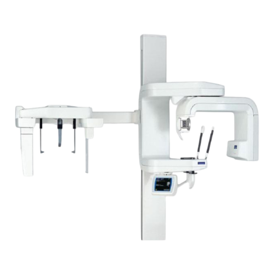
- Page 1 PLANMECA Proline XC Pan/Ceph Calibration Manual...
- Page 2 IEC364. Equipment is used according to the operating instructions Planmeca pursues a policy of continual product development. Although every effort is made to produce up-to-date product documentation this publication should not be regarded as an infallible guide to current specifications. We reserve the right to make changes without prior notice.
-
Page 3: Table Of Contents
Table of Contents Chapter A: General Information Disclaimer Required Tools 2.1. Calibration Tools 2.1.a. Digital Panoramic 2.1.b. Digital Cephalometric 2.2. Hand Tools Chapter B: Panoramic Beam Alignment 1.1. Collimator 0 1.1.a. High / Low 1.1.b. Left / Right 1.1.c. Angled 1.2. - Page 4 Chapter C: Cephalometric Beam Alignment Collimator C 1.1.a Too Left 1.1.b Too Right 1.1.c High / Low Collimator D 1.2.a Left 1.2.b Right Ceph Head Leveling Computer Setup Left / Right 2.2.a Left 2.2.b Right Up / Down 2.3.a 2.3.b Down Beaver Tail Left / Right High / Low...
-
Page 5: Chapter A: General Information
Chapter General Information DISCLAIMER This manual contains the information required to setup and calibrate the Planmeca Proline XC Panoramic with Cephalometric X-ray unit for Digital. WARNING Protect yourself from radiation when you are checking the beam alignment and calibrating. Since radiation safety requirements vary from state to state, country to country, it is the responsibility of the installer to ensure that the correct precautions are observed. - Page 6 - 6 -...
-
Page 7: Required Tools
REQUIRED TOOLS Calibration Tools 2.1. 2.1.a. Digital Panoramic Ball phantom (part number 50971) used for checking the position of the Patient Positioning Mechanism and the Positioning lights. (Figure 1) Figure 1 Frankfort plane alignment tool (part number 50977) used with the ball phantom for checking the position of the Frankfort plane light. -
Page 8: Digital Cephalometric
Sensor alignment tool (part number 10002699) used for checking the beam alignment. (Figure 4) Figure 4 Panoramic mode calibration block, red calibration block, (part number 665413) used for calibrating the panoramic sensor head. (Figure 5) Figure 5 2.1.b. Digital Cephalometric Cephalostat calibration tool (part number 10002935) used for calibrating the cephalostat. -
Page 9: Hand Tools
Left and Right ear posts (part number 651003, 651005) used for aligning the ball and ring on the cephalostat. (Figure 7) Figure 7 2.2 Hand Tools 2 mm allen wrench 2.5 mm allen wrench 3 mm allen wrench 4 mm allen wrench Short •... - Page 10 - 10 -...
-
Page 11: Chapter B: Panoramic
Chapter Panoramic Beam Alignment Removing the covers Unscrew the Tube head cover with a 3mm allen (Figure 8) and remove the front cover. Figure 8 Unhook the two corners of the C-Arm cover and remove the cover. (Figure 9a & 9b) Figure 9a Figure 9b - 11 -... - Page 12 Primary Collimator Press the i button in the lower left-hand corner. (Figure 10) Figure 10 Press the down arrow and press Service Settings (Figure 11) Figure 11 The password is 1701. (Figure 12) Press the down arrow four times and press Primary Collimator Figure 12 - 12 -...
-
Page 13: Collimator
NOTE: Make sure beam alignment tool is attached to the sensor alignment tool. (Figure 13) Figure 13 1.1 Collimator 0 (adult) Now press the exposure button to see where the radiation beam is hitting the screen. The beam image should appear within the borders of the rectangle markings on the alignment tool. -
Page 14: High / Low
1.1.a High / Low If the beam is too high or too low then loosen the two screws on the face of the collimator with a 2.5 mm allen. (Figure 15) Figure 15 Tighten the bottom screw and take another exposure to check the alignment. -
Page 15: Angled
1.1.c Angled If the beam is angled, loosen up the three screws at left, top, and bottom with a 1.5 mm allen. (Figure 17a-c) Figure 17a Figure 17b Figure 17c Tighten the screws and take another exposure at the beam. Repeat if still angled. -
Page 16: Collimator
1.2 Collimator 1 (child) Now press the exposure button to see where the radiation beam is hitting screen. The beam image should appear within the borders of the rectangle markings on the fluorescent screen. The beam should fill, from the bottom up, three quarters of the alignment tool. -
Page 17: Beam Check
Beam Check NOTE: Make sure that the x-ray machine is connected to the computer 2.1 Connecting to a computer Plug a CAT-5 into the isolated port on the keyboard processor. (Figure 20 & 20a) Figure 20a Figure 20 Plug a planet cable into the base of the XC. (Figure 21) Figure 21 Plug that planet cable into a y-connector, dongle. -
Page 18: Network Interface Box Connections
2. Y-connector, dongle 3. CAT-5 cable (port 1) 4. Power cable 2.1.b Didapi Configuration Click Start, Click All Programs and select Planmeca, then select Didapi Configuration. Click on Ethernet Interface. The default ip address is 192.168.0.135 Click on Proline which will open Windows Notepad. Put the... - Page 19 Press Beam Check. (Figure 25) Figure 25 NOTE: If the sensor was calibrated first, remember to remove the red calibration block from the collimator. Press Panoramic which will bring you to the Beam Check Panoramic screen. (Figure 26) Figure 26 - 19 -...
-
Page 20: Beam Check On The Computer
2.3 Beam Check on the computer NOTE: Make sure the sensor is in the sensor holder. Click on Start, Click All Programs then Planmeca then Beam Check then click Proline Pan Press Ready on the touch screen then press the exposure button. (Figure 27) Figure 27 Image should be the same top and bottom, left and right. -
Page 21: Calibrating
3.1 Setting up the computer Close Beam Check and open Dimax3 Tool 3.1.a Dimax3 Tool Click on Start, Click All Programs then Planmeca then Dimax3 Tool Click on Settings and select Type and click on Proline. (Figure 29) Figure 29 Click on Calibrate and select Pan. -
Page 22: Turning Radiation Off/On
3.1.b Turning Radiation Off/On 3.1.b.i OFF Press the smile in the middle right of the touch screen. (Figure 31) Figure 31 Press all the arrows at the bottom of the touch screen, turning each from white to red. (Figure 32) Figure 32 3.1.b.ii ON Press the smile in the middle right of the right of the touch... -
Page 23: C Kv/Ma Settings For Panoramic
NOTE: Make sure the red calibration block is placed onto the collimator before calibrating. (Figure Figure 33 3.1.c kV/mA settings for Panoramic BINNING 3.1.d Changing Binnings Click Settings and select Binning then the appropriate binning. (Figure 34) Figure 34 Press the Ready icon after turning the radiation off or on. Take an exposure. -
Page 24: Ball Phantom
Ball Phantom 4.1 Setting up Touch Screen Place the ball phantom in the Patient Positioning Mechanism. (Figure 36) Figure 36 Alignment lasers Hold the layer right button for 1 second. (Figure 37) Figure 37 Adjust the layer so that it is at zero with the layer arrow fields. (Figure 38) Figure 38 - 24 -... - Page 25 Look at where the lasers are lining up on the ball phantom. This is the starting reference point. (Figure 39) Figure 39 Setting the kV/mA Press the kV/mA at the top left of the screen on the touch screen. (Figure 40) Figure 40 Select the 60kV / 4mA then click “OK.”...
- Page 26 Enabling Auto Return Press the i in the lower right corner on the touch screen. (Figure 42) Figure 42 Press Behavioral Preferences. (Figure 43) Figure 43 Press Auto Return This will turn the cassette holder to auto return to entry position after each exposure shot.
-
Page 27: Dimaxis Pro
4.2 Dimaxis 4.x.x Click on Start, Click All Programs and select Planmeca, then select Dimaxis Pro 4.1.4. Click OK then click OK again. Select New from the bottom of the Select Image screen Press Ready on the touch screen and take an exposure. -
Page 28: Checking Image
4.3 Checking image There will be an image of 23 balls on the films; one Center Ball and 11 balls to the left and right. NOTE: Make sure Center Ball is round before moving onto the 10 ball distances. 4.3.a Center Ball NOTE: Center ball will be above the midsagittal bar of the ball phantom. -
Page 29: Too Thin
The ball should be 7mm top to bottom and left to right. (Figure 49) Figure 49 4.3.a.i Too thin If the ball is too thin then move the layer to the right. (Figure Figure 50 Take another exposure and check ball size again. If the right size, check 10 ball. -
Page 30: Th Ball
4.3.b 10 Ball Measure from the left end of the Center Ball to the 10 Ball on the right then measure from the right end of the Center Ball to the 10 Ball. (Figure 52) Figure 52 4.3.b.i Too Left If the distance from the Center Ball to the left is more than the right, then move the table away from the column. -
Page 31: B.ii Too Right
4.3.b.ii Too Right If the distance from the Center Ball to the right is more than the left, then move the table toward the column. (Figure 54) Figure 54 4.3.b.iii Moving the Table Unscrew the four screws on the table with a 4mm allen. (Figure 55) Figure 55 Take another exposure and check Ball Phantom... -
Page 32: Shadow Ball
4.3.c Shadow Ball NOTE: The oval above the Center Ball. (Figure 56) Figure 56 4.3.c.i Too Left/ Too Right If the shadow ball is too left or right, press the left or right button on the touch screen. (Figure 57) Figure 57 NOTE: Pressing the left button will move the beam to the right and right will move the beam to the left. -
Page 33: Patient Positioning Light Alignment
4.4 Patient Positioning Lights Alignment After aligning the Ball Phantom, turn the Patient Positioning Lights on again by holding the layer right button for 1 second. (Figure 58) Figure 58 NOTE: Make sure layer is at zero when aligning positional lights. If layer is not at zero need to zero- out layer before aligning beams. - Page 34 Press Service Settings. (Figure 60) Figure 60 Press Patient positioning adjustment (Figure 61) Figure 61 - 34 -...
- Page 35 The screen will say Please Wait then show the number 0. Press Back until at start up screen. (Figure 62) Figure 62 Place the Ball Phantom into the Patient positioning mechanism with the Frankfort plane alignment tool on top of the Ball Phantom. (Figure 63) Figure 63 - 35 -...
-
Page 36: Midsaggital Light Beam
4.4.a Midsagittal Light Beam If the midsagittal light is not lined up with the center line on the Ball phantom, then finger adjust the mirror until it lines up. (Figure 64) Figure 64 4.4.b Frankfort Light Beam If the Frankfort light is not straight on the Frankfort plane tool, then adjust the barrel of the laser. -
Page 37: Focal Layer Light Beam
4.4.c Focal Layer Light Beam If the focal layer light is not straight on the Ball Phantom, then finger adjust the mirror until it lines up. (Figure 66) Figure 66 - 37 -... - Page 38 - 38 -...
-
Page 39: Chapter C: Cephalometric
Chapter Cephalometric Entering Cephalometric Mode Press Pan on the touch screen and select Ceph. (Figure 67) Figure 67 Beam Alignment Primary Collimator Press the i button in the lower left-hand corner. (Figure 68) Figure 68 - 39 -... - Page 40 Press the down arrow and press Service Settings (Figure 69) Figure 69 Press the down arrow four times and press Primary Collimator Press Next until C appears on the touch screen. (Figure 70) Figure 70 NOTE: Collimator C is a manually adjusted alignment with 4mm and 6mm allens. - 40 -...
-
Page 41: Collimator C
Attach the sensor alignment tool to the sensor holder with the fluorescent screen attached to it. One Up to Down and the other Up to the right and Down to the left. (Figure 71) Figure 71 1.1 Collimator C There are two screws on the back left hand side of the Cephalometric arm. (Figure 72) Figure 72 The beam should look like:... -
Page 42: Too Left
1.1.a Too Left If the beam is too left then unscrew right of screw with a 6mm and tighten the left screw with a 4mm. (See Figure 72) Take another exposure. If aligned then move onto Collimator d. 1.1.b Too Right If the beam is too right then unscrew the left screw with a 4mm and tighten the right screw with a 6mm. -
Page 43: Left
1.2.a Left If the beam is too left, then press the right button on the touch screen. (Figure 74) Figure 74 Take another exposure and check the beam. If aligned, press next until you get back to d and re-check to make sure unit held adjustments. 1.2.b Right If the beam is too right, then press the left button on the touch screen. -
Page 44: Ceph Head Leveling
Ceph Head Leveling Put the left and right ear posts into their respective holders. (Figure 76) Figure 76 2.1 Computer Setup Click on Start then Run. (Figure 77) Figure 77 Type in pmsample then click OK. (Figure 78) Figure 78 - 44 -... - Page 45 Uncheck Use calibration. (Figure 79) Figure 79 Click on Cephalo. (Figure 80) Figure 80 Set the kV / mA to 62 kV and 6 mA Press Ready on the touch screen. (Figure 81) Figure 81 - 45 -...
- Page 46 Ball should be within ring. (Figure 82) Figure 82 If the ball is outside the ring then remove the cover with a 2.5mm allen. (Figure 83) Figure 83 NOTE: Will need a wrench and pliers to adjust left or right. (Figure 84) Figure 84 - 46 -...
-
Page 47: Left / Right
2.2 Left / Right 2.2.a Left To move the ball left, tighten the rod towards the column. (Figure 85) Figure 85 After adjusting, do a new beam check and calibration. 2.2.b Right To move the ball right, loosen the rod away from the column. (See Figure 85) After adjusting, do a new beam check and calibration. -
Page 48: Beaver Tail
Beaver Tail (Secondary Collimator) Attach the beaver tall to the unit by first removing the cover by unscrewing the 4mm screw with an allen. (Figure 86) Figure 86 Unscrew the two screws attached to the top of the beaver tall with a 4mm allen and attach that to the closest side to the tube head, or across from the sensor holder. - Page 49 Move the fluorescent screen so that it is going from left and right to up and down, respectively. NOTE: The touch screen should still be in Primary Collimator showing the d collimator and the sensor alignment tool should still be on the sensor holder. Press the exposure switch to see where the beaver tall is collimating the beam.
-
Page 50: Left / Right
3.1 Left / Right If the beam is too left or right, loosen the two screws closest to the tubehead with a 4mm and slide left or right depending on what is needed. (Figure 89) Figure 89 Take another exposure and check alignment, if still off adjust again. If aligned then re-tighten the screws and take a final exposure to make sure nothing has shifted. -
Page 51: Angled
NOTE: If unable to move beaver tall up or down after loosen these screws, take a 2.5mm allen and loosen slightly the two screws on the beaver tall that are towards the front of the machine. (Figure 91) Figure 91 Re-tighten the middle screw to hold the adjusted position and take another exposure, if still off adjust again. -
Page 52: Right
3.3.b Right Un-tighten the top side screw with a 2.5mm allen and tighten the bottom screw in. (See Figure 92) Take an exposure, adjust as needed. Beam Check NOTE: Remember to put the sensor into the sensor holder before continuing. NOTE: Make sure that the x-ray machine is connected to computer 4.1 Setting up beam check Press the i icon on the lower hand corner of the touch screen. - Page 53 Press Cephalometric which will bring you to the Beam Check Cephalometric screen. (Figure 95) Figure 95 Select Proline Ceph on the computer in Beam Check. Image should be the same top and bottom, left and right. (Figure 96) Figure 96 Follow Section 1.1.a.i-iii on pgs.
-
Page 54: Calibrating
Calibrating Press Beam Check Cephalometric then choose Ceph. (Figure 97) Figure 97 Press Collimator until it shows the number 6. (Figure 98) Figure 98 5.1 kV / mA Binnings - 54 -... -
Page 55: Computer
(Figure 99) Figure 99 NOTE: Change binnings by clicking Settings and select Binnings then the appropriate binning in Dimax3tool. (Figure 100) Figure 100 5.2 Computer Click on Start, Click on All Programs then Planmeca then Dimax3 Tool. - 55 -... -
Page 56: Dimax3 Tool
5.3 Dimax3 Tool Click on Start then click on type then select Proline. (Figure 101) Figure 101 Click on Calibrate then select Ceph (Figure 102) Figure 102 Click Ready on the touch screen and take an exposure NOTE: image will come out as being a grey hatchet with black around it. (Figure 103) Figure 103 Press the L key on the keyboard of the computer to give calibration lines. -
Page 57: Not Together
5.3.a Not together If the image comes out separated check to make sure that the hatchet is placed in the holder correctly. 5.3.a.i Raising up If hatchet is place correctly, then raise the beaver tail up. If the beam is too high or low, loosen the three screws on the back of the beaver tall that are at the top closest the sensor holder. - Page 58 www.planmecausa.com - 58 -...
Need help?
Do you have a question about the Proline XC Panoramic and is the answer not in the manual?
Questions and answers