Table of Contents
Advertisement
Advertisement
Table of Contents

Related Manuals for Icom ID-RP2010V


Summary of Contents for Icom ID-RP2010V
- Page 1 SERVICE MANUAL VHF REPEATER ID-RP2010V S-15801XZ-C1 August 2021...
- Page 2 7. READ the instructions of the test equipment thoroughly before connecting it to the repeater. Icom, Icom Inc. and the Icom logo are registered trademarks of Icom Incorporated (Japan) in Japan, the United States, the United Kingdom, Germany, France, Spain, Russia, Australia, New Zealand, and/or other countries.
-
Page 3: Table Of Contents
TABLE OF CONTENTS SECTION 1 SPECIFICATIONS SECTION 2 INSIDE VIEWS SECTION 3 DISASSEMBLY INSTRUCTION SECTION 4 OPTIONAL PRODUCT INSTALLATION INSTALLING THE LTE MODULE (UX-262)……………………………………………………………………… 4-1 CONNECTING A GATEWAY SERVER ………………………………………………………………………… 4-7 REPEATER SETTINGS …………………………………………………………………………………………… 4-8 SECTION 5 INTERFACE INFORMATION SECTION 6 ADJUSTMENT PROCEDURE PREPARATION ……………………………………………………………………………………………………... -
Page 4: Specifications
SECTION 1 SPECIFICATIONS GENERAL 144 ~ 148 MHz • Operating frequency range: 144 ~ 146 MHz • Type of emission: 50 Ω nominal • Antenna impedance: N-Type • Antenna connector type: –10˚C ~ +50˚C, 14˚F ~ +122˚F • Operating temperature range: •... -
Page 5: Inside Views
SECTION 2 INSIDE VIEWS ETHERNET ISOLATION TRANSFORMER • FRONT-L UNIT (T10) J21 ([SD CARD]) • FRONT-R UNIT J1255 J2002 J1801 J1951... - Page 6 • MAIN UNIT 3.3 V REGULATOR DV DSP (IC1011) (IC502) CPLD* FLASH ROM* (IC8813) (IC331) J9151 J5201 ([RPT1/RPT2]) J1621 J7402 ([SP]) J881 J5101 ([CONT I/O]) DC–DC CONVERTER CIRCUIT USB BRIDGE OCTAL BUS BUFFER (IC1551) (IC5101) A/D CONVERTER TRIPLE INVERTER (IC2101) (IC5108) J301 +5 V REGULATOR...
- Page 7 • RF-TX UNIT FORWARD/REFLECTED WAVE DETECTED VOLTAGE BUFFER (IC691) POWER AMPLIFIER (Q301) DRIVE AMPLIFIER (Q201) POWER AMPLIFIER BIAS VOLTAGE BUFFER (IC211) PRE-DRIVE AMPLIFIER (IC101) J101...
- Page 8 • RF-RX UNIT PRE AMPLIFIER SWITCH (Q701) RF AMPLIFIER (IC1161) +5 V REGULATOR (IC1162) J1201 CURRENT DETECTOR (IC51) SCHOTTKY DIODE (D22) ZENER DIODE (D23) POWER MOSFET (Q31) 5 A FUSE (F21)
-
Page 9: Disassembly Instruction
SECTION 3 DISASSEMBLY INSTRUCTION 1. Removing the FRONT-R and FRONT-L UNITS 2. Removing the RF UNIT ASSEMBLY 1) Remove the 7 screws from the top cover, then remove the 1) Remove the 2 screws from the rear panel of the repeater top cover from the repeater chassis. - Page 10 3. Removing the RF-RX and RF-TX UNITS 1) Remove the 15 screws from the top cover, then remove it. 3) Remove the 21 screws and disconnect the cables from the RF-RX and RF-TX UNITS. 15 screws RF-RX UNIT RF-TX UNIT J1201 J101 Top cover...
- Page 11 4. Removing the MAIN UNIT 1) Turn the RF UNIT ASSEMBLY upside down. Chassis (RF UNIT ASSEMBLY) 2) Remove the 15 screws, and disconnect the 8 cables from the MAIN UNIT. J2881 J9151 MAIN UNIT J9541 J3081 J3101 J9001 J9101 ×15 screws 3) Remove the MAIN UNIT from the chassis in the direc- tion of the arrow.
-
Page 12: Optional Product Installation
SECTION 4 OPTIONAL PRODUCT INSTALLATION NOTE: For the latest information, refer to the UX-262 SETTING GUIDE that is available from the Extranet. 4-1 INSTALLING THE LTE MODULE (UX-262) ■ SUPPLIED ACCESSORIES Spare flat cable (7.5 × 80 mm, 0.3 × 3.1 in) Certification sticker LTE antennas* (For only the USA version) - Page 13 ■ INSTALLING THE UNIT 4) Remove the PCB (FRONT-R UNIT: 1), and then attach 1) Remove the screws, and then remove the top cover. the unit (2). 5) Secure the unit using the screws removed in step 3. L Firmly tighten the screws in the order shown below. 6) Reattach the cables removed in step 2.
- Page 14 ■ INSTALLING THE UNIT (CONTINUED) 8) Remove the nuts and washers from the straight connectors on the supplied coaxial cables. Coaxial cable Washer 9) Attach one end of the cables to the connectors on the unit (1), and then attach the other ends through the holes in the repeaterʼs rear panel (2)where the caps were located.
- Page 15 ■ INSTALLING THE SIM CARD Install valid SIM cards, as shown below. Caution for handling the nanoSIM cards: • To avoid damage from static discharge, touch a metal object such as a doorknob or a metal window sash to remove any static electricity that may be accumulated in your body before handling the nanoSIM cards.
- Page 16 ■ VERIFICATION Use the Utility for ID-RP3 to verify that the repeater recognizes the installed unit. 1) Connect the PC to the repeater with a unit D Troubleshooting L See the instruction manual included with the repeater for details of USB driver settings, utility installation, The repeater does not turn ON: and connection instructions.
- Page 17 ■ PLACING ANTENNAS D Attaching antennas D Securing antennas Attach the supplied antennas as shown below. Remove the protection sheet on the antenna surface, and then paste antennas on the window glass. L Clean the window glass using the supplied cleaning cloth before pasting.
-
Page 18: Connecting A Gateway Server
4-2 CONNECTING A GATEWAY SERVER ■ USING A GATEWAY SERVER Connect a Gateway server to the repeater to use an LTE network. Trust server LTE network Internet eth0 (To the LTE) Gateway server (Linux PC) eth1 (To the repeater) -
Page 19: Repeater Settings
4-3 REPEATER SETTINGS This section describes about the required IP address and LTE settings in the Utility for ID-RP3. L The IP addresses shown in the figure are examples. Set appropriate IP addresses according to your environment. ■ USING A GATEWAY SERVER Digital Network Trust server... - Page 20 ■ UTILITY FOR ID-RP3 SETTINGS (COMMON) L If your repeater is already in operation online, skip this topic. The settings shown below are the minimum required to use D Squelch Level the Digital Repeater function. See the Utility for ID-RP3 Enter the squelch level at which the squelch just opens, and HELP for more details for other setting items.
- Page 21 ■ UTILITY FOR ID-RP3 SETTINGS (GATEWAY SETTINGS) L If your repeater is already in operation online, skip this topic. Settings shown below are required if operating the repeater as a Gateway. D Using a Gateway server 1) Select “Use Gateway Server” in “Gateway” (1). L The option “Use Simple gateway”...
- Page 22 ■ UTILITY FOR ID-RP3 SETTINGS (NETWORK SETTINGS) D Using a Gateway server D Time Settings Turn the Network Time Protocol (NTP) function ON or OFF. If the NTP function is “ON,” the repeater gets the exact time Using the DHCP Client function: through the network.
- Page 23 ■ LTE SETTINGS D Using a Gateway server D SIM card settings 1) Select “OFF” in “DHCP” (1). Enter the APN, User Name, Password, and Authentication Type provided by the mobile carrier. L If “ON” is selected in “SIM Auto Switch,” enter the 2) Enter the fixed IP address and Subnet Mask (2 3).
-
Page 24: Interface Information
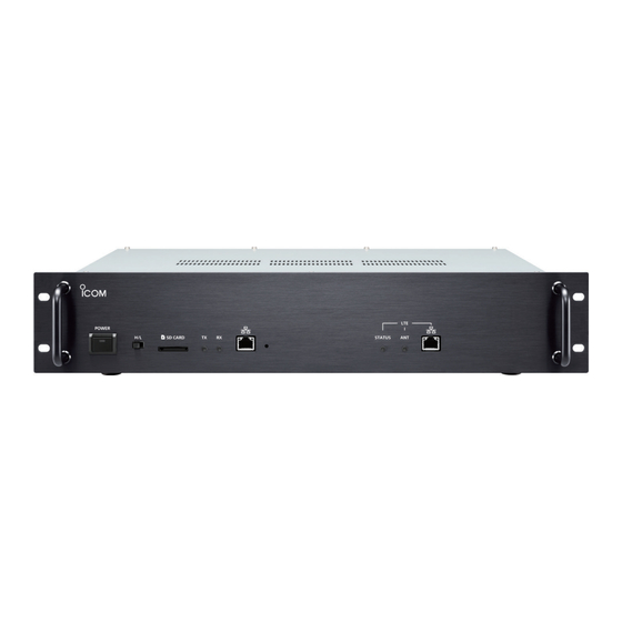
SECTION 5 INTERFACE INFORMATION • FRONT PANEL [LAN 1] [LAN 2] [LAN 1] [LAN 1] Indication Description Specification • Lights when a cable is connected. 1 LINK/ACT • Does not light when a cable is not connected. • Blinks while communicating. Connects to a Gateway server when operating in the •... - Page 25 • REAR PANEL [CONT I/O] [USB] [RPT1]/[RPT2] [EXT-SP (SERVICE)] [REF IN 10MHz] [CONT I/O] [CONT I/O] Description Connects to the LAN port of the ID-RP2C using a supplied control cable, when the repeater system is operating as a gateway or assist repeater with the ID-RP2C.
-
Page 26: Adjustment Procedure
SECTION 6 ADJUSTMENT PROCEDURE 6-1 PREPARATION ■ REQUIRED EQUIPMENT EQUIPMENT GRADE AND RANGE EQUIPMENT GRADE AND RANGE Adjustment software ID-RP3 ADJ Programming cable USB cable ( Supplied with the repeater) Frequency range: 0.1 ~ 300 MHz Output voltage: 13.8 V Standard signal Output level: −20 to 90 dBμV... - Page 27 To use the USB cable between the repeater and a PC, you must first install a USB driver. The latest USB driver and installation guide can be downloaded from the Icom website. Carefully read the guide, before installing the driver.
- Page 28 ■ ABOUT THE ADJUSTMENT SOFTWARE (ID-RP3 ADJ) Toolbar Clcik to open the Adjustment screen (Refer to page 6-5) Clcik to open the Test screen (Refer to page 6-4) 1 File 3 COM Port The File menu contains sub-menus that you use to open, Setting and save data file, and to exit the software.
- Page 29 0/1 Repeat: Data bits “0” and “1” are repeatedly transmitted. 4 TX/RX Frequency (DD) PN9 data is transmitted. PN9: This item is not for the ID-RP2010V. PN15: PN15 data is transmitted. All 1: Only data bit “1” is transmitted.
- Page 30 ■ ABOUT THE ADJUSTMENT SCREEN On the Adjustment screen, you can adjust the repeater. • Perform the Repeater All Reset after you have finished the adjustment. Adjustment value in hexadecimal • Click [Start] to start the adjustment. • Click [Stop] to quit the adjustment. “VHF”...
-
Page 31: Transmit Adjustments And Verifications
6-2 TRANSMIT ADJUSTMENTS AND VERIFICATIONS * The repeater automatically transmits while pushing the PC’s [←], [→], or [ENTER] key. Be sure to select the appropriate power range before pushing keys. REPEATER’S ADJUSTMENT ITEM NAME OPERATION VALUE CONDITION IDLING [VDL IDL Set] •... -
Page 32: Frequency Verification
6-3 FREQUENCY VERIFICATION † The output level of the signal source is measured at the load end (PD). REPEATER’S ADJUSTMENT ITEM NAME OPERATION VALUE CONDITION REFERENCE [REF OSC1] • Receiving • Connect the 10 MHz reference frequency “OK” is displayed FREQUENCY source to the [REF IN 10 MHz] connector, in the Result row. -
Page 33: Parts List
SECTION 7 PARTS LIST [FRONT-L UNIT] PART PART DESCRIPTION DESCRIPTION LOCATION LOCATION 1590004690 S.TRA LDTC143ZET1G 18.4/28.0 2260002590 SWI SKHHLU 1590004690 S.TRA LDTC143ZET1G 75.5/4.0 2220000631 SWI MFS201N-16-Z 1590004690 S.TRA LDTC143ZET1G 88.5/4.1 5910001380 S.TRA TS8121CM HF 111.4/25.1 6200011910 S.COI BLM31PG330SN1L 99.7/26.8 EP12 6910016330 S.BEA MMZ1005S 601CT-S 76.6/34.6... - Page 34 [MAIN UNIT] PART PART DESCRIPTION DESCRIPTION LOCATION LOCATION IC101 1140017780 S.IC R7S721001VCBG T 162.5/55.0 Q8811 1590004690 S.TRA LDTC143ZET1G 20.8/114.7 IC171 1110007780 S.IC NJU7704F3-28A-TE1 T 180.1/32.1 Q8821 1590004690 S.TRA LDTC143ZET1G 13.8/114.2 IC181 1130018090 S.IC EN25QH64A-104HIP T 159.0/71.8 Q8822 1590004690 S.TRA LDTC143ZET1G 17.7/114.8 IC195 1130016621 S.IC...
- Page 35 [MAIN UNIT] PART PART DESCRIPTION DESCRIPTION LOCATION LOCATION L3052 6200009220 S.COI LQW18AN15NG00D R128 7030016250 S.RES RMC1/16S-220JTH (22) T 147.3/61.3 (LQW1608A15NG00) 70.8/17.4 R129 7030016250 S.RES RMC1/16S-220JTH (22) T 145.3/60.7 L3073 6200010910 S.COI LQW18AN56NG00D 81.8/18.9 R130 7030016250 S.RES RMC1/16S-220JTH (22) T 147.3/60.2 L3081 6200010910 S.COI LQW18AN56NG00D...
- Page 36 [MAIN UNIT] PART PART DESCRIPTION DESCRIPTION LOCATION LOCATION R444 7030016150 S.RES RMC1/16S-100JTH (10) T 102.2/92.4 R1261 7030013780 S.RES RCC16R020FTP 5.0/21.2 R445 7030016150 S.RES RMC1/16S-100JTH (10) T 103.3/92.4 R1262 7030015910 S.RES RMC1/16S-101JTH (100) 7.2/22.6 R446 7030016150 S.RES RMC1/16S-100JTH (10) T 103.9/90.9 R1263 7030021710 S.RES RG1608P-273-D-T5 (27 k)
- Page 37 [MAIN UNIT] PART PART DESCRIPTION DESCRIPTION LOCATION LOCATION R2551 7030016290 S.RES RMC1/16S-222JTH (2.2 k) T 103.4/28.6 R3011 7030016050 S.RES RMC1/16S-102JTH (1 k) 59.6/39.3 R2552 7030016080 S.RES RMC1/16S-822JTH (8.2 k) T 100.5/30.5 R3012 7030016440 S.RES RMC1/16S-272JTH (2.7 k) 58.4/38.9 R2553 7030016320 S.RES RMC1/16S-225JTH (2.2 M) T 105.5/27.4 R3013...
- Page 38 [MAIN UNIT] PART PART DESCRIPTION DESCRIPTION LOCATION LOCATION R7356 7030016510 S.RES RMC1/16S-4R7JTH (4.7) T 23.3/101.3 R8811 7030015970 S.RES RMC1/16S-103JTH (10 k) T 23.5/109.0 R7357 7030015910 S.RES RMC1/16S-101JTH (100) T 24.5/101.7 R8812 7030015900 S.RES RMC1/16S-470JTH (47) 28.6/110.5 R7501 7030016050 S.RES RMC1/16S-102JTH (1 k) T 22.5/103.7 R8813 7030016050 S.RES...
- Page 39 [MAIN UNIT] PART PART DESCRIPTION DESCRIPTION LOCATION LOCATION C127 4030023010 S.CER 0402B104K160CT B 154.7/46.3 C1001 4030020190 S.CER GRM32EB31C476KE15L T 69.9/134.0 C128 4030023010 S.CER 0402B104K160CT B 154.7/45.4 C1002 4030023010 S.CER 0402B104K160CT T 74.2/132.1 C129 4030023010 S.CER 0402B104K160CT B 163.7/45.6 C1003 4030023010 S.CER 0402B104K160CT T 71.4/136.5 C130...
- Page 40 [MAIN UNIT] PART PART DESCRIPTION DESCRIPTION LOCATION LOCATION C2032 4030023010 S.CER 0402B104K160CT T 189.7/67.6 C3054 4030026590 S.CER RF15N180J500CT 72.0/18.9 C2034 4030022930 S.CER 0402N821J500CT T 191.3/67.6 C3055 4030026710 S.CER RF15N2R0B500CT 72.9/17.8 C2035 4030019560 S.CER GRM21BB31C106KE15L T 195.1/67.8 C3056 4030026590 S.CER RF15N180J500CT 74.7/20.4 C2081 4030022690 S.CER...
- Page 41 [MAIN UNIT] PART PART DESCRIPTION DESCRIPTION LOCATION LOCATION C7501 4030023010 S.CER 0402B104K160CT 26.5/99.0 C8601 4030023030 S.CER 0402B103K250CT 110.9/37.2 C7502 4030023010 S.CER 0402B104K160CT T 25.2/104.3 C8602 4030023010 S.CER 0402B104K160CT T 107.1/36.0 C7503 4030022510 S.CER GRM155B31A225KE95D T 25.4/100.4 C8603 4030023090 S.CER 0402B102K500CT T 107.1/36.9 C7504 4030023010 S.CER...
- Page 42 [MAIN UNIT] PART PART DESCRIPTION DESCRIPTION LOCATION LOCATION C9201 4030023030 S.CER 0402B103K250CT 181.4/5.6 EP1212 6910018930 S.BEA MPZ2012S601A T 51.5/130.5 C9202 4030023030 S.CER 0402B103K250CT 179.4/5.6 EP1551 6910023350 S.BEA MMZ1005B601CT T 163.8/147.4 C9203 4030022630 S.CER 0402N100C500CT 177.9/7.7 EP1601 6910023350 S.BEA MMZ1005B601CT T 164.2/148.6 C9204 4030022630 S.CER 0402N100C500CT...
- Page 43 [MAIN UNIT] PART DESCRIPTION LOCATION EP9505 6910019900 S.BEA MPZ1608S601AT T 173.3/108.5 EP9506 6910023350 S.BEA MMZ1005B601CT T 173.8/106.5 M.=Mounted side (T: Mounted on the Top side, B: Mounted on the Bottom side) Eqv.= This component is equivalent to the REF No. component listed above, H/V LOCATION=See the BOARD LAYOUTS for details.
- Page 44 [RF-TX UNIT] PART PART DESCRIPTION DESCRIPTION LOCATION LOCATION IC101 1110009820 S.IC MMG3H21NT1 25.3/27.3 C301 4030021020 S.CER GRM31A5C2J101JW01D 54.1/30.0 IC211 1110008550 S.IC NJM2904CRB1-TE1 35.9/33.1 C302 4030020770 S.CER GRM31A5C2J330JW01D 55.7/24.3 IC691 1110008550 S.IC NJM2904CRB1-TE1 T 142.2/46.2 C303 4030021300 S.CER GQM22M5C2H330JB01L 72.7/37.5 C305 4030021280 S.CER GQM22M5C2H180JB01L 82.3/24.3...
- Page 45 [RF-RX UNIT] PART PART DESCRIPTION DESCRIPTION LOCATION LOCATION IC51 1110007950 S.IC INA199A2DCKR 40.3/11.0 C1154 4030022750 S.CER 0402N221J500CT 81.0/47.1 IC1161 1110009890 S.IC NJG1152KA1-TE1 75.8/49.8 C1155 4030022900 S.CER 0402N680J500CT 80.6/48.3 IC1162 1180004760 S.REG S-1200B33-M5T1U 70.3/57.7 C1161 4030023030 S.CER 0402B103K250CT 77.4/51.2 C1162 4030023030 S.CER 0402B103K250CT 73.8/48.7 C1163...
- Page 46 [FRONT-R UNIT] PART DESCRIPTION LOCATION J1255 6510019421 S.CON B8B-ZR-SM4-TF 56.9/40.2 J1801 6510022801 S.CON B10B-PH-SM4-TB 12.3/18.4 J1951 6510024040 CON TM11R-5M2-88-LP *0 J2002 6510022022 S.CON 14FLT-SM2-TB 10.8/37.1 M.=Mounted side (T: Mounted on the Top side, B: Mounted on the Bottom side) Eqv.= This component is equivalent to the REF No. component listed above, H/V LOCATION=See the BOARD LAYOUTS for details.
-
Page 47: Mechanical Parts
SECTION 8 MECHANICAL PARTS [FRONT-L UNIT] [MAIN UNIT] PART PART DESCRIPTION QTY. DESCRIPTION QTY. 6510022472 40FLT-SM2-TB (LF) (SN) (M) J101* 6510025142 10FLT-SM2-TB (LF) (SN) (M) 6510015541 B4B-ZR-SM4-TF (LF) (SN) J301* 6510027290 52808-0671 J21* 6510034190 DM1AA-SF-PEJ (82) J302* 6510025760 B5B-ZR-SM4-TF (LF) (SN) 6510024040 TM11R-5M2-88-LP J311* 6510022022 14FLT-SM2-TB (LF) (SN) (M) - Page 48 [FRONT-R UNIT] PART DESCRIPTION QTY. J1255* 6510019421 B8B-ZR-SM4-TF (LF) (SN) J1801* 6510022801 B10B-PH-SM4-TB (LF) (SN) J1951* 6510024040 TM11R-5M2-88-LP J2002* 6510022022 14FLT-SM2-TB (LF) (SN) (M) [ACCESSORIES] PART DESCRIPTION QTY. 5210001360 ATQ 25A 5210001430 11930011 (BFLP 5A 58V) 8900022020 OPC-2361 8900010530 OPC-1045 8900022600 OPC-2423 8860001320 HEX WRENCH 3MM 8930105980 RUBBER STAND (R) SF104...
- Page 49 • CHASSIS ASSEMBLY MP114 (CHASSIS) (8110011760) MP94 (CHASSIS) ×7 (8810007410) MP118 (CHASSIS) (8930102450) Torque: 1.0 N·m (±0.15 N·m) MP92 (CHASSIS) (8810003401) • MP112 rear view Torque: 1.0 N·m (±0.15 N·m) MP92 (CHASSIS) (8810003401) W206 (CHASSIS) (8920003390) W204 (CHASSIS) (8910000220) MP112 (CHASSIS) RF UNIT ASSEMBLY (Refere to the parts list.) MP40 (CHASSIS)
- Page 50 • RF UNIT ASSEMBLY Top view Bottom view MP91 (CHASSIS) ×15 (8810008661) MP104 (CHASSIS) (8510022900) MP55 (CHASSIS) ×15 (8810008661) Torque: 0.5 N·m (±0.07 N·m) Torque: 0.5 N·m (±0.07 N·m) MP60 (CHASSIS) MP60 (CHASSIS) (8810007131) (8810007131) MP53 (CHASSIS) ×9 MP53 (CHASSIS) ×9 (8810008661) MP52 (CHASSIS) ×10 (8810008661)
-
Page 51: Board Layouts
SECTION 9 BOARD LAYOUT ETH_RESET LTE_RESET DCDC_EN LTE_STATUS_LED LTE_FTMODE LTE_SIM_SEL2 LTE_ANT_LED LTE_SIM_SEL1 LTE_SIM_DET LTE_PWRKEY LTE_STATUS • FRONT-L UNIT (B-9081D: Top view) HR3V EP51 EP51 PW_LED PWRK 3R3V B-9081D B-9081D FRONT-L FRONT-L H10 H15 H20 H25 H30 H35 H40 H45 H50 H55 H60 H65 H70 H75 H80 H85 H90 H95 H100 H105 H110 H115 H120 H125 H130 H135 H140 H145 H10 H15 H20 H25 H30 H35 H40 H45 H50 H55 H60 H65 H70 H75 H80 H85 H90 H95 H100 H105 H110 H115 H120 H125 H130 H135 H140 H145 [SD CARD] [TX]... - Page 52 • FRONT-L UNIT (B-9081D: Bottom view) H10 H15 H20 H25 H30 H35 H40 H45 H50 H55 H60 H65 H70 H75 H80 H85 H90 H95 H100 H105 H110 H115 H120 H125 H130 H135 H140 H145 NOTE: Some parts may not be mounted on the PCB. See the PARTS LIST H/V location on the PARTS LIST for location details.
- Page 53 [RPT1] [RPT2] [USB] • MAIN UNIT (B-9074D: Top view) D– J1621 [CONT I/O] [DV/DD] J5201 [CONT I/O RPT] [SERVICE] J2881 J9151 J1621 J7402 J5201 J7402 J7402 J5101 C1623 C1623 EP2265 EP2265 C1618 C1618 Q1621 Q1621 R2805 R2805 R2804 R2804 R2244 R2244 J5101 C1614...
- Page 54 • MAIN UNIT (B-9074D: Bottom view) H95 H100 H105 H110 H115 H120 H125 H130 H135 H140 H145 H150 H155 H160 H165 H170 H175 H180 H185 H190 H195 H200 H205 H210 H215 H95 H100 H105 H110 H115 H120 H125 H130 H135 H140 H145 H150 H155 H160 H165 H170 H175 H180 H185 H190 H195 H200 H205 H210 H215 MP8603 J7402 [SERVICE]...
- Page 55 • RF-TX UNIT (B-9077B: Top view) C320 C320 EP301 EP301 C316 C316 W209 C317 C317 C318 C318 R661 R661 R662 R662 R666 R666 C661 C661 R691 R691 IC691 IC691 EP302 EP302 W210 R612 R612 R611 R611 C313 C313 R613 R613 C312 C312 C505...
- Page 56 • RF-TX UNIT (B-9077B: Bottom view) H10 H15 H20 H25 H30 H35 H40 H45 H50 H55 H60 H65 H70 H75 H80 H85 H90 H95 H100 H105 H110 H115 H120 H125 H130 H135 H140 H145 H150 H155 H160 H165 MP301 MP302 NOTE: Some parts may not be mounted on the PCB.
- Page 57 • RF-RX UNIT (B-9078B: Top view) L502 L502 C1164 C1164 L502 L502 C1163 C1163 C502 C502 MP701 R1164 R1164 C705 C705 L1161 L1161 C706 C706 J2 (CHASSIS) C1162 C1162 C1173 C1173 C1155 C1155 C1103 C1103 C1101 C1101 C408 C408 C1174 C1174 L1171 L1171...
- Page 58 • RF-RX UNIT (B-9078B: Bottom view) H10 H15 H20 H25 H30 H35 H40 H45 H50 H55 H60 H65 H70 H75 H80 H85 H90 H95 H100 H105 H110 H115 H120 H125 H130 H135 H140 H145 H150 H155 H160 H165 NOTE: Some parts may not be mounted on the PCB. See the PARTS LIST H/V location on the PARTS LIST for location details.
- Page 59 J1255 GND(SHIELD) ETH_USB_DM ETH_USB_DP LTE_USB_DM • FRONT-R UNIT (B-9159C: Top view) LTE_USB_DP USB-ETHER USB-ETHER HMP1801 HMP1801 J1255 J1255 J1255 J2002 SIM1 SIM1 J2002 J2002 J2002 ETH_RESET LTE_RESET DCDC_EN LTE_STATUS_LED LTE_FTMODE LTE_SIM_SEL2 LTE_ANT_LED LTE_SIM_SEL1 LTE_SIM_DET LTE_PWRKEY LTE_STATUS HR3V J1801 SIM2 SIM2 MAIN MAIN J1801...
- Page 60 • FRONT-R UNIT (B-9159C: Bottom view) H10 H15 H20 H25 H30 H35 H40 H45 H50 H55 H60 H65 H70 H75 H80 H85 H90 H95 H100 H105 H110 H115 H120 H125 H130 H135 H140 H145 H150 H155 NOTE: Some parts may not be mounted on the PCB. See the PARTS LIST H/V location on the PARTS LIST for location details.
-
Page 61: Wiring Diagram
SECTION 10 WIRING DIAGRAM [DC13.8V] [RX ANT] [TX ANT] W131(CHASSIS) J8801 CAB-1327 EXT-REF EP21 EP22 W209(CHASSIS) DC-IN EP62 EP301 CAB-1405 J5101 RF-RX UNIT W210(CHASSIS) RF-TX UNIT EP63 EP302 CAB-1406 CONT I/O J5201 1 A1 2 A2 3 A3 4 A4 5 A5 6 A6 7 A7... -
Page 62: Block Diagram
SECTION 11 BLOCK DIAGRAM MAIN UNIT FRONT-L UNIT Explanatory notes 3R3V CONTROL Line 3R3V H3R3V H3R3V COMMON Line P_LED+ 3R3V SD3R3V SD3R3V IC8701 TX Line For DAC SamplingClock P_LED- PW_LED CTRL CGSDO/CGSDIO/CGSCLK/CGCS OUT1 DIV2 DACK_P RX Line PWR_SW 1179.648MHz Clock DACK_N Generator OUT2... - Page 63 MAIN UNIT IC7601 FTHML FPGA IC5241 IC2101 EXPANDER IC2102 DCLK_P BLOCK (3/3) MODI DCLK_N IC5201/IC5211/ J5201 IC5221/IC5231 A-ch IC2102 BUFF MICI [RPT1/RPT2] RPT_TX1/RPT_RX1/RPT_TX2/RPT_RX2/ RPT_TX3/RPT_RX3/RPT_TX4/RPT_RX4/ B-ch RPT_CDSEL/RPT_CDCK/RPT_SRES/RPT_ERES BUFF IC181 I2S bus line FLASH IC171 H3R3V RES1 RESET IC5108 12.288MHz DVCK IC201 VDET DSP_TD S2801...
- Page 64 MAIN UNIT MAIN UNIT (ALC BLOCK) IC51 (POWER SUPPLY BLOCK) IC2601/Q2601 CURRENT IC2541 BLOCK (1/3) VFORLP POCV BLOCK (2/3) IDLP IC1011 IC1001 Q2541/Q2551/Q2552 (13.8V) IC1041/IC1042 DC13.8V H3R3V H3R3V H3R3V IC2601 IC2541 DC-DC ALC-CTRL H3R3V H1R18V H1R18V METER ALCL VREFLP 3R3V DC-DC (13.8V) IC1042...
-
Page 65: Voltage Diagram
SECTION 12 VOLTAGE DIAGRAM • FRONT-L UNIT • FRONT-R UNIT 3R3V 3R3V 3R3V LTE_LAN J1951 PWRK EP13 MPZ1608S601A 3R3V 3R3V H3R3V H3R3V H3R3V SD3R3V VDD(3R3V) SDWP SD_WP SD3R3V SD_CD SDCD SDDAT1 SD_D1 LDTC143ZE SD_D0 SDDAT0 SDCMD SD_CMD PW_LED SD_CLK SDCLK SDDAT3 SD_D3 POWER... - Page 66 • MAIN UNIT (1/14) H3R3V H3R3V H3R3V H3R3V EP104 MMZ1005B601C DA5V DA5V DA5V DA5V H3R3V_ EP101 MMZ1005B601C H3R3V_ H3R3V_ H1R18V EP102 MPZ1608S601A H1R18V_ H1R18V H1R18V H1R18V H3R3V 3R3V R289 H3R3V C186 FTHML_ FTHML_ IC101 IC101 IC101 IC101 MAIN (11/14) C159 0.001 R7S721001VCBG R7S721001VCBG...
- Page 67 • MAIN UNIT (2/14) H3R3V H3R3V H3R3V H3R3V H3R3V H3R3V 3R3V 3R3V 3R3V VEPL_ MAIN CPU VEPL_ UEPL_ SCSCK SCSCK UEPL_ SCRXD SCRXD MAIN (4/14) VTHML_ SCTXD SCTXD VTHML_ UTHML_ SCTRG SCTRG R450 UTHML_ 12THML_ SCACK SCACK R449 4.7k 12THML_ SCRES SCRES R448...
- Page 68 • MAIN UNIT (3/14) CP514 DIG_CK DIG_DAT CONT.I/O DSP_TD MAIN (14/14) R576 100k DX_DVTX I2S2_RX DR_DVTX I2S2_DX MAIN CPU R558 CP515 DSP_ARX DSP_ARX R559 MAIN (1/14) DSP_ARX CP516 DSP_ADX DSP_ADX DSP_ADX CONT.I/O DV_RC 96 kHz DSP_RC DV_RD 3.3 V DSP_RD MAIN (14/14) DV_TC DSP_TC...
- Page 69 CONNECT BLOCK • MAIN UNIT (4/14) PA8V MAIN (5/14) PA8V PA8V H3R3V EP9003 MPZ2012S102A EP9002 MPZ2012S102A PA8V PA8V EP9001 MPZ2012S102A MAIN (2/14) J9001 MAIN (9/14) DDRXS DDRXS MAIN (2/14) EP9004 MMZ1005Y102CT VDIDV EP9005 MMZ1005Y102CT VFIDV R9006 R9602 VEPL VEPL_ R9010 MAIN (2/14) UEPS UEPL...
- Page 70 POWER-REG BLOCK • MAIN UNIT (5/14) DCLK_P MAIN (12/14) DCLK_N MAIN (5/14) MAIN (5/14) +14V +14V +14V +14V MP1001 3183 EP1001 MAIN (12/14) FC1R1V MPZ2012S601A FC1R1V FC1R1V FC1R1V MAIN (5/14) 3.9 V H3R3V MAIN (1,2,4,6,9/14) H3R3V H3R3V H3R3V H3R3V USB3R3V MAIN (6/14) 3.3 V USB3R3V...
- Page 71 REMOTE/LAN BLOCK • MAIN UNIT (6/14) USB connected 0 V 4.3 V USB not connected 3.3 V VBUS VBUS MAIN (5/14) H3R3V H3R3V H3R3V H3R3V H3R3V USB3R3V USB3R3V USB3R3V USB3R3V Q1621 LDTC143ZE R1621 R1553 UDTXD J1621 MAIN (1/14) R1554 GPIO.4 CHR1 [USB] UDRXD...
- Page 72 DAC / LPF / AMP • MAIN UNIT (7/14) MAIN (9/14) AFOS 13.3 V R2201 C2201 MAIN (5/14) R2024 3.9k L2203 R2202 DA5V DA5V DA3R3V DA5V C2023 820P R2021 R2023 IC2021 D2201 R2025 R2204 3.9k L1SS400 TS462CPT C2203 R2207 C2204 C2209 R2022 MCLK...
- Page 73 ANALOG • MAIN UNIT (8/14) 3R3V 3R3V 3R3V 3R3V MAIN (5/14) Q2561 VFORLP VFORLP LDTC143ZE UFORLP UFORLP Q2562 R2562 12FORLP 12FORLP NASBS VREFLP VREFLP MAIN (4/14) 3.3M IC2601 UREFLP UREFLP LDTA114YE R2603 12REFLP 12REFLP IDLP IDLP 3.1 V Q2601 NASBS NASBS L2SC4081 R2608...
- Page 74 • MAIN UNIT (9/14) 3R3V 3R3V 3R3V 3R3V 3R3V 3R3V H3R3V H3R3V DRESL MAIN (2/14) DRESL IC2801 DRESL MDAT MSTB MDAT MAIN (1/14) MDAT R2801 RPT_S1 MAIN (2/14) DSTB AFOS MAIN (7/14) AFOS DSTB RPT_S2 MSTB MAIN (1/14) MSTB RPT_S3 MAIN (2/14) PASTB PASTB...
- Page 75 • MAIN UNIT (10/14) MAIN (4/14) 7.8 V 5.0 V 4.9 V IC3501 R3501 MAIN (5/14) AAL5V AAL5V VOUT AAL5V AAL5V AAL5V C3011 C3021 C3041 XC6209F502MR Legend 0.01 0.01 0.01 R3011 R3042 R3041 R3012 R3021 5.0 V R3022 Q3032 7.4 V LDTC143ZE 2.7k 2.7k...
- Page 76 • MAIN UNIT (11/14) RF-DAC (IC7201) Data Lines 147.456 MHz (LVDS) 1.5 V DACLK_P 1.5 V ****_P 147.456 MHz LVDS DACLK_N 0.9 V ****_N 0.9 V A3R3V DA3R3V A3R3V DA3R3V 1R8V FP2R5V MAIN (12/14) DASLP DASLP DAALA 1R8V DAALA FP2R5V FP2R5V DATXE DATXE...
- Page 77 • MAIN UNIT (12/14) DA3R3V DA3R3V FP_TXD FP_TXD EP8051 FP_CLK FP_CLK MAIN (2/14) DA3R3V FP_STB FP_STB MPZ1608S601A FP2R5V RZ_A1 RZ_A1 RZ_A2 RZ_A2 FP2R5V MAIN (5/14) RZ_A3 RZ_A3 RZ_A4 RZ_A4 FC1R1V RZ_A5 RZ_A5 IC7601 5CEFA9F23I7N RZ_A6 RZ_A6 VREFB7AN0 FC1R1V RZ_A7 RZ_A7 DIFFIO_RX_T9p/GND VCCIO7A RZ_A8...
- Page 78 • MAIN UNIT (13/14) 49.152 MHz 49.152 MHz 1.1 V 6.3 V 98.304 MHz 6.6 V 3.2 V 0.1 V 3.7 V C3R3V C3R3V C3R3V C3R3V MAIN 5/14) FP2R5V FP2R5V FP2R5V FP2R5V EP8602 MMZ1005Y102CT 1.0 V 196.608 MHz 3.4 V R8662 0.58 V R8622...
- Page 79 • MAIN UNIT (14/14) 3.3 V EP5101 3R3V MAIN (5/14) 3R3V MMZ1005B601C C5113 IC5108 MAIN (9/14) DV_CONT_IO DSP_TD DSP_RD C5108 TC7WH04FU MAIN (3/14) IC5101 J5101 DSP_RC R5101 DSP_RE RSSI R5102 RSSI R5103 RSSI DSP_TC R5104 [Cont.I/O] R5105 R5106 R5107 TC74AC541FT MAIN (14/14) CPU_TE J5201...
- Page 80 • RF-TX UNIT 13.7 V EP301 OT-047 L302 EP215 LW-33 MPZ2012S102A 1632 To RF-RX UNIT EP302 OT-047 MP302 L601 1.5U C311 Q301 R202 [TX ANT] IC101 L501 L502 L503 MMG3H21NT1 Q201 C310 PD85004 J101 LA-176 LA-179 LA-176 L652 R102 R105 MP701 C502 100P...
- Page 81 • RF-RX UNIT 0.002 IC51 2.1 V 0.001 EP41 INA199A2 13.7 V MPZ2012S102A TO RF-TX UNIT EP42 1193-0011BFLP_5A_58V MPZ2012S102A EP21 OT-047 FHA040 [DC-IN] Power ON 13.6 V EP22 TJ50S06M3L Power OFF LDTC114EE OT-047 Power ON 1.3 V Power OFF 13.6 V Legend CP701 CP700...
- Page 82 If you have any inquiries regarding service, contact your distributor. The contact number or E-mail address of your distributor can be found on our website. https://www.icomjapan.com/...
- Page 83 S-15801XZ-C1 1-1-32, Kamiminami, Hirano-ku, Osaka 547-0003, Japan © 2021 Icom Inc.
Need help?
Do you have a question about the ID-RP2010V and is the answer not in the manual?
Questions and answers