Table of Contents
Advertisement
Quick Links
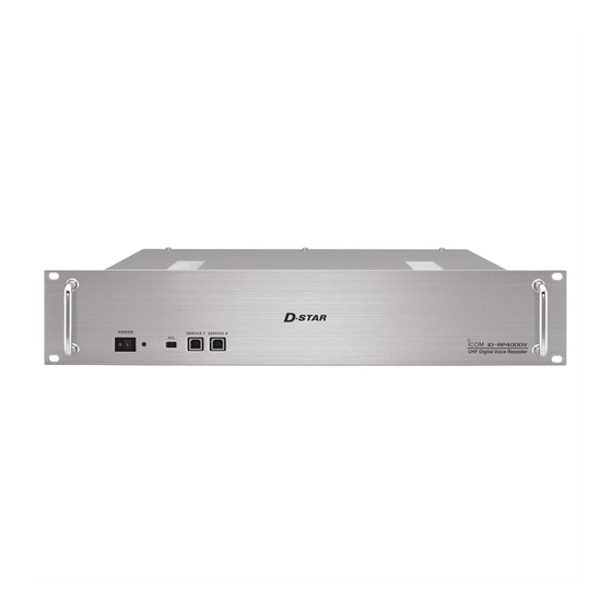
UHF DIGITAL VOICE REPEATER
id- rp4000v
Instruction Manual
This device complies with Part 15 of the FCC rules. Operation
is subject to the following two conditions: (1) This device may
not cause harmful interference, and (2) this device must accept
any interference received, including interference that may cause
undesired operation.
Advertisement
Table of Contents

Related Manuals for Icom ID-RP4000V


Summary of Contents for Icom ID-RP4000V
- Page 1 UHF DIGITAL VOICE REPEATER id- rp4000v Instruction Manual This device complies with Part 15 of the FCC rules. Operation is subject to the following two conditions: (1) This device may not cause harmful interference, and (2) this device must accept any interference received, including interference that may cause undesired operation.
-
Page 2: Important
R WARNING HIGH VOLTAGE! NEVER use harsh solvents such as benzine or alco- touch an hol to clean the ID-RP4000V, as they will damage the antenna or internal antenna connector during transmis- ID-RP4000V’s surfaces. If the ID-RP4000V becomes sion. This may result in an electrical shock or burn. -
Page 3: Table Of Contents
■ Front panel ............2 ■ Rear panel ............2 6 REPEATER SETTINGS ........27 ■ Frequency setting for ID-RP4000V ....27 ■ 3 INSTALLING AND CONNECTING ....3–5 7 MAINTENANCE ..........28 Attaching an “N” connector ....... 3 ■... -
Page 4: System Outline
The ID-RP4000V is installed into the Digital Smart ■ Technologies for Amateur Radio (D-STAR) repeater system for operation. • The ID-RP4000V is a 440 MHz digital voice and The ID-RP4000V never functions as a repeater without slow-speed data repeater and connects to (4.8 kbps) -
Page 5: Panel Descriptions
PANEL DESCRIPTIONS Front panel ■ q w e r t q POWER SWITCH [POWER] r SERVICE CONNECTOR T [SERVICE T] (p. 27) Push to turn ON the power. Connect a PC with an A-B type USB cable to set the transmit frequency. -
Page 6: Installing And Connecting
15 mm (0.59 in) 6 mm (0.24 in) 3 mm (0.12 in) Power supply requirements ■ Make sure that the DC power supply that is used with the ID-RP4000V system meets the following require- ments: Output voltage: 13.8 V DC ±15% Current capacity: At least the total current consumption of the connected equipment. -
Page 7: Installing In A System Rack
INSTALLING AND CONNECTING Installing in a system rack ■ The ID-RP4000V is designed to be installed in a stan- dard EIA 19-inch rack. Use the supplied bolts with the rack. We recommend using a rack that has rails because the weigh of the ID-RP4000V is approximately 7.5 kg (16.5 lbs) -
Page 8: System Connections
(Assist 2) (Assist 1) (purchase separately) to AH-106*/107* to AH-106*/107* OPC-1380 (supplied w/ID-RP2C) ID-RP2C OPC-1309 Duplexer (supplied w/ID-RP4000V) ID-RP4000V (User supplied) External DC power Control cable supply 13.8 V (supplied w/ID-RP4000V) Black Coaxial cables (User supplied) AC outlet... -
Page 9: Installing The Drivers
Uninstall the USB driver for ID-1 first, then install the In addition, individual USB driver installations are re- USB driver for the ID-RP4000V, if the USB driver for quired for each connector, because the communica- the ID-1 is installed in the PC. - Page 10 Click Select The window shown below will appear. Click Click “Browse my computer for driver software.” !1 Click [Next] to start the installation of “ID-RP4000V SERVICE T” driver software. Click Click “Browse for driver software on your computer” will appear.
- Page 11 “ ” in the “Device manager,” and then click “Update Driver Software...” on the menu. !5 Repeat y to !3 , to install the “ID-RP4000V SER- VICE T” driver software. !6 Eject the CD from the CD drive, and then restart the...
-
Page 12: Microsoft Windows 8
“ ” is displayed, as shown • When installing the driver, log in as the administrator. below. Insert the CD that is supplied with the ID-RP4000V NOTE: Although the warning symbol “ ” indicates that (Application CD) into the CD drive. - Page 13 INSTALLING THE DRIVERS The window shown below will appear. !1 Click [Next] to start the installation of “ID-RP4000V Click “Browse my computer for driver software.” SERVICE T” driver software. Click Click “Browse for driver software on your computer” will !2 When the Windows Security screen appears, click appear.
- Page 14 “ ” in the “Device manager,” and then click “Update Driver Software...” on the menu. !5 Repeat y to !3 , to install the “ID-RP4000V SER- VICE T” driver software. !6 Eject the CD from the CD drive, and then restart the...
-
Page 15: Microsoft Windows 7
“ ” is displayed, as shown • When installing the driver, log in as the administrator. below. Insert the CD that is supplied with the ID-RP4000V NOTE: Although the warning symbol “ ” indicates that (Application CD) into the CD drive. - Page 16 !5 The dialog “Device driver software was not success- fully installed” will appear again. w Click !6 Repeat u to !4 , to install the “ID-RP4000V SER- VICE T” driver software. !2 “Browse for driver software on your computer” will !7 Eject the CD from the CD drive, and then restart the appear again.
-
Page 17: Microsoft Windows Vista
“Install this driver software anyway” to continue. • When installing the driver, log in as the administrator. Insert the CD that is supplied with the ID-RP4000V (Application CD) into the CD drive. • If you download the USB driver, skip this step and go to the next step. - Page 18 INSTALLING THE DRIVERS ■ Microsoft ® Windows Vista ® — continued !0 When the Windows Security screen appears, click “Install this driver software anyway” to continue. Click !1 After the installation is completed, “The software for this device has been successfully installed” will ap- pear.
-
Page 19: Checking The Com Port
Checking the COM port ■ After the driver installation, check the driver availability and the COM port number. In this section, checking the COM port number of the ID-RP4000V [SERVICE T] connector is used for in- struction example. Microsoft ® Windows ®... - Page 20 • When opening the Device Manager, log in as the admin- Manager” screen to check the COM port number. istrator. • When the driver is completely installed, “ICOM ID- Connect the PC and the ID-RP4000V [SERVICE T] RP4000V SERVICE T (COMM)” is displayed. The screen connector with the USB cable.
- Page 21 • When opening the Device Manager, log in as the admin- Manager” screent o check the COM port number. istrator. • When the driver is completely installed, “ICOM ID- Connect the PC and the ID-RP4000V [SERVICE T] RP4000V SERVICE T (COMM)” is displayed. The screen connector with the USB cable.
- Page 22 • When opening the Device Manager, log in as the admin- ager” screen to check the COM port number. istrator. • When the driver is completely installed, “ICOM ID- Connect the PC and the ID-RP4000V [SERVICE T] RP4000V SERVICE T (COMM)” is displayed. The screen connector with the USB cable.
-
Page 23: Uninstalling The Usb Driver
Double-click “Universal Serial Bus controllers” on • When uninstalling the driver, log in as the administrator. the “Device Manager” screen. w Connect the PC and the ID-RP4000V [SERVICE T] con- • “ICOM ID-RP4000V SERVICE T” appears. nector with the USB cable. - Page 24 Double-click “Universal Serial Bus controllers” on • When uninstalling the driver, log in as the administrator. the “Device Manager” screen. w Connect the PC and the ID-RP4000V [SERVICE T] con- • “ICOM ID-RP4000V SERVICE T” appears. nector with a USB cable...
- Page 25 Double-click “Universal Serial Bus controllers” on • When uninstalling the driver, log in as the administrator. the “Device Manager” screen. w Connect the PC and the ID-RP4000V [SERVICE T] con- • “ICOM ID-RP4000V SERVICE T” appears. nector with a USB cable...
- Page 26 Double-click “Universal Serial Bus controllers” on • When uninstalling the driver, log in as the administrator. the “Device Manager” screen. w Connect the PC and the ID-RP4000V [SERVICE T] con- • “ICOM ID-RP4000V SERVICE T” appears. nector with a USB cable...
-
Page 27: Installing The Utility Software
• Quit all other applications if any are running. • When uninstalling the driver, log in as the administrator. Insert the CD that is supplied with the ID-RP4000V (Application CD) into the CD drive. Click “Computer” and then display the contents of the CD. - Page 28 INSTALLING THE UTILITY SOFTWARE ■ Installing— continued The “Choose Destination Location” screen ap- NOTE: After installing the utility, the short cut icon pears. will automatically be created on the desktop. • When installing the Utility software at the displayed loca- When the icon looks like white square, right-click on tion, click [Next>].
-
Page 29: Uninstalling The Utility Software
Open “Control Panel” in the Start menu, and then The screen appears as shown below when the un- click “Uninstall a program.” installation starts. Click Right-click the “Icom ID-RP4000V,” then click “ Unin- stall/Change”. The screen appears as shown below when the un- installation is completed. Click [Finish]. -
Page 30: Repeater Settings
Enter the COM port number. Click NOTE: See pages 16 to 19 for the COM port num- ber confirmation details. t The utility reads the ID-RP4000V setting and the screen as at left appears when the correct COM port number is set. w Click y Enter the specified receive and transmit frequen- cies into “RX/TX Frequency”... -
Page 31: Maintenance
■ DO NOT use harsh solvents such as benzine or alcohol If a fuse blows, or the ID-RP4000V stops functioning, when cleaning, as they can damage the ID-RP4000V’s find the source of the problem, repair it, and then re- surfaces. -
Page 32: Specifications And System Units
SPECIFICATIONS AND SYSTEM UNITS Specifications ■ D General • Frequency range U.S.A.: Tx/Rx 440 to 450 MHz Europe: Tx/Rx 430 to 440 MHz • Type of emission: (GMSK: F7W for system operation) • Frequency stability: ±0.8 kHz (based on 25˚C (+77˚F)) •... -
Page 33: Country Code List
COUNTRY CODE LIST • ISO 3166-1 Country Codes Country Codes Austria 18 Liechtenstein Belgium 19 Lithuania Bulgaria 20 Luxembourg Croatia 21 Malta Czech Republic 22 Netherlands Cyprus 23 Norway Denmark 24 Poland Estonia 25 Portugal Finland 26 Romania 10 France 27 Slovakia 11 Germany 28 Slovenia... - Page 34 MEMO...
- Page 35 MEMO...
- Page 36 ■ ■ ■ ■ ■ ■ ■ ■ ■ ■ ■ ■ ■ ■ ■ ■ ■ ■ ■ ■ ■ ■ ■ ■ ■ ■ A-6448H-1EX-r Printed in Japan 1-1-32 Kamiminami, Hirano-ku, Osaka 547-0003, Japan © 2006–2014 Icom Inc.
Need help?
Do you have a question about the ID-RP4000V and is the answer not in the manual?
Questions and answers