Icom id-rp2 Instruction Manual
Digital repeater system
Hide thumbs
Also See for id-rp2:
- Instruction manual (52 pages) ,
- Service manual (150 pages) ,
- Instruction manual (36 pages)
Table of Contents
Advertisement
Quick Links
Download this manual
See also:
Service Manual
Advertisement
Table of Contents

Subscribe to Our Youtube Channel
Related Manuals for Icom id-rp2


Summary of Contents for Icom id-rp2
- Page 1 DIGITAL REPEATER SYSTEM id- rp2 Instruction Manual...
-
Page 2: Important
CAUTION: Changes or modifications to this repeater, R WARNING! NEVER apply more than 16 V DC not expressly approved by Icom Inc., could void to the [DC 13.8V IN] connector on the repeater. This your authority to operate this repeater under FCC could cause a fire or damage the repeater. -
Page 3: Table Of Contents
FOR CLASS B UNINTENTIONAL RADIATORS This equipment has been tested and found to comply If this equipment does cause harmful interference to with the limits for a Class B digital device, pursuant to radio or television reception, which can be determined part 15 of the FCC Rules. -
Page 4: System Outline
SYSTEM OUTLINE ID-RP2D A Digital Smart Technologies for Amateur Radio (D- ■ STAR) repeater can be constructed by combining the ➥ The ID-RP2D is a 1.2 GHz data repeater (128 kbps) following equipment, depending on your site plan. and connects to the ID-RP2C. ID-RP2C: Repeater controller * The ID-RP2D never functions as a stand-alone repeater ID-RP2D: 1.2 GHz data repeater... -
Page 5: System Outline
SYSTEM OUTLINE D AH-106 : 10 GHz parabolic antenna 800 (d) D AH-107 : 10 GHz parabolic antenna 450 (d) ➥ Both AH-106 and AH-107 are offset parabolic an- tenna and connect to ID-RP2L. Up to 20 km * or 8 km (approximately;... -
Page 6: Supplied Accessories
SUPPLIED ACCESSORIES Accessories for ID-RP2C ■ q Power cable ..... 1 (OPC-1380; approx. 3 m; 10 ft) w CD (USB driver, Utility software)......1 e Rubber feet ............4 r Spare fuses ........2 (FGB01 30A) Accessories for ID-RP2D/ID-RP2V ■ q Power cable .... -
Page 7: Accessories For Ah-106
SUPPLIED ACCESSORIES Accessories for AH-106 ■ q Element arm ............1 w Element ..............1 e Elevation support plate ......... 1 r Support arms ............2 Accessories for AH-107 ■ q Pole stopper ............1 w Pole clamp ............1 e Clamp base ........ -
Page 8: Panel Descriptions
DC POWER CONNECTOR u POWER CONNECTOR [DC 13.8V IN] (p. 10) [ASSIST 1— DC 13.8V OUT] DC power input connector for the ID-RP2 system. Connects the ID-RP2L’s power cable. Connects a 13.8 V DC power supply unit with the... -
Page 9: Id-Rp2D (Front Panel)
PANEL DESCRIPTIONS ID-RP2D (Front panel) ■ q POWER SWITCH [POWER] e SERVICE CONNECTOR [SERVICE] (p. 42) Push to turn ON the power. Connects a PC with an A-B type USB cable to set The LED indicator located at right lights when the the both transmit and receive frequencies. -
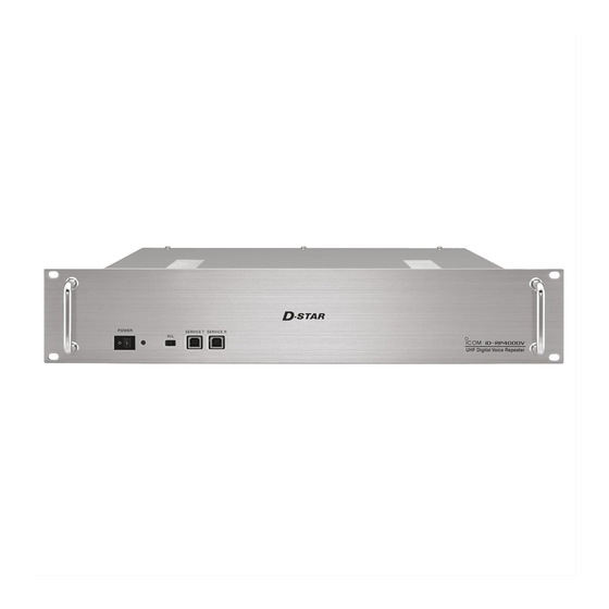
Page 10: Id-Rp2V (Front Panel)
PANEL DESCRIPTIONS ID-RP2V (Front panel) ■ w e r q POWER SWITCH [POWER] e SERVICE CONNECTOR T [SERVICE T] (p. 43) Push to turn ON the power. Connects a PC with an A-B type USB cable to set The LED indicator located at right lights when the the transmit frequency. -
Page 11: Id-Rp2L (Not Available In European Countries)
(Reboot the ID-RP2L. If the indicator is still flashing even after rebooting, Front view * See p. 17 for test plug assembling and connections de- contact authorized Icom dealer tails. or distributor.) • Flashing fast : Setting data malfunction. t DATA CABLE CONNECTOR B [DATA B] (p. 10) -
Page 12: Installing And Connecting
Make the distance between the [GND] terminal and Make sure that the DC power supply that is used ground as short as possible. with the ID-RP2 system is meet the following requirements: R WARNING! NEVER connect the [GND] a gas Output voltage: 13.8 V DC ±15%... -
Page 13: System Connections
INSTALLING AND CONNECTING System connections ■ ID-RP2L* ID-RP2L* AH-108* (Assist 2) (Assist 1) to AH-106/107* to AH-106/107* Antenna OPC-1380 filter (supplied w/ID-RP2C) ID-RP2C OPC-1309 (supplied w/ID-RP2D/V) ID-RP2V Duplexer Control cable (supplied w/ID-RP2D/V) OPC-1309 (supplied w/ID-RP2D/V) Coaxial cables External DC power (purchase separately) supply 13.8 V Black... -
Page 14: Antenna Assembling (Not Available In European Countries)
INSTALLING AND CONNECTING Antenna assembling ■ (Not available in European countries) R DANGER! Antenna installation is intended for professional installation only. We are not responsi- ble for any building breakage, any damage resulting from a drop of the antenna from a high place or un- stable site or resulting from any personal injury nor any accident in any other cases. -
Page 15: Element
INSTALLING AND CONNECTING Pole t Attach the pole between the elevation angle bracket (48.6–89.1 mm) and the pole clamp, that is removed in steps q, as Stopper illustrated at left. • Tighten the two bolts within an even torque. • Use the stopper of the elevation angle bracket when installing the antenna at the top edge of the pole. -
Page 16: Clamp Base (W/Bolts)
INSTALLING AND CONNECTING AH-107 q Attach the element arm to the parabolic reflector Bolts using with the supplied bolts and the ele- (M6×30) M6×30 ment arm fitting plates. Note: Check the orientation. Element-arm Reflector fitting plate Elevation base angle bracket Reflector Element arm Element-... - Page 17 INSTALLING AND CONNECTING r Fix the supplied pole with the pole clamp as illus- trated at left. Pole clamp Pole stopper Pole (Supplied item) t Attach the antenna element to the element holder. Element NOTE: The “Z” stamps on the antenna element must be face up.
-
Page 18: Nuts (M8)
INSTALLING AND CONNECTING AH-108 q Attach the nut to the radial, then attach the ra- (M6) AH-108 dial to the AH-108. w Attach the supplied bolts, pole clamps, spring wash- Pole (30–60 mm) ers, flat washers and nuts to the AH-108 as illus- trated at left. -
Page 19: Id-Rp2L Installation
INSTALLING AND CONNECTING ID-RP2L installation ■ The ID-RP2L must be directly connected to the para- R DANGER! The ID-RP2L installation is in- bolic antenna element. tended for professional installation only. We are not The element cable extension may cause communica- responsible for any building breakage, any damage tion error, therefore the ID-RP2L must be installed right resulting from dropping the ID-RP2L from a high... -
Page 20: Adjusting The Parabolic Antenna
INSTALLING AND CONNECTING Adjusting the parabolic antenna ■ About the test plug Assemble the test plug before adjusting the parabolic to + (voltmeter) Voltmeter antenna as follows. q Short TEST terminals of the pin 2 ( pin 3 ( test plug, that is supplied with the ID-RP2L. w Connect a voltmeter between pin 1 (RSSI) and pin 4 (GND). -
Page 21: Driver Installations
DRIVER INSTALLATIONS Use an A-B type USB (Universal Serial Bus) cable be- IMPORTANT! tween the ID-RP2 and your PC. So, the USB driver A different USB driver from the ID-1 is used for the installation is required for the PC. -
Page 22: Driver Installations
DRIVER INSTALLATIONS Right-click on the device icon with the warning sym- !0 Select the “DRIVER” folder in the application CD, bol “ ,” and then click “Update Driver Software...” on or the unzip driver file (downloaded driver file), and the menu. then click [OK]. - Page 23 DRIVER INSTALLATIONS !3 After the installation is completed, the “Windows has successfully updated your driver software” will appear. Click [Close]. Click !4 Again, right-click on the device icon with the warn- ing symbol “ ” in the “Device manager,” and then click “Update Driver Software...”...
-
Page 24: Microsoft ® Windows ® 7
DRIVER INSTALLATIONS Microsoft ® Windows ® ■ Start Windows. The “Device Manager” window appears, then make • Quit all other applications if any are running. sure a warning symbol “ ” is displayed, as shown • When installing the driver, log in as the administrator. below. - Page 25 DRIVER INSTALLATIONS The window shown below will appear. !1 Click [Next] to start the installation of “ID-RP2C Click “Browse my computer for driver software.” SERVICE 1” driver software. Click Click The “Browse for driver software on your computer” !2 When the Windows Security screen appears, click will appear.
-
Page 26: Microsoft ® Windows ® 7
DRIVER INSTALLATIONS Microsoft ® Windows ® ■ Start Windows. The “Device Manager” window appears, then make • Quit all other applications if any are running. sure a warning symbol “ ” is displayed, as shown • When installing the driver, log in as the administrator. below. - Page 27 DRIVER INSTALLATIONS !0 The “Browse for driver software on your computer” !3 When the Windows Security screen appears, click will appear. Click [Browse...]. [Install] to continue. Click Click !4 After the installation is completed, “Windows has successfully updated your driver software” will ap- pear as shown below.
-
Page 28: Microsoft ® Windows Vista
DRIVER INSTALLATIONS Microsoft ® Windows Vista ® ■ q Start Windows. When the Windows Security screen appears, click • Quit all other applications if any are running. “Install this driver software anyway” to continue. • When installing the driver, log in as the administrator. Insert the CD that is supplied with the ID-RP2C (Ap- plication CD) into the CD drive. - Page 29 DRIVER INSTALLATIONS !0 When the Windows Security screen appears, click “Install this driver software anyway” to continue. Click !1 After the installation is completed, “The software for this device has been successfully installed” will ap- pear. Click [Close]. Click !2 Eject the CD from the CD drive, and then restart the PC.
-
Page 30: Checking The Com Port
• When opening the Device Manager, log in as the admin- Manager” screen to check the COM port number. istrator. • When the driver is completely installed, “ICOM ID-RP2C Connect the PC and the ID-RP2C [SERVICE 1] SERVICE 1 (COMM)” is displayed. The screen shows connector with the USB cable. -
Page 31: D Microsoft Windows 8
• When opening the Device Manager, log in as the admin- Manager” screen to check the COM port number. istrator. • When the driver is completely installed, “ICOM ID-RP2C Connect the PC and the ID-RP2C [SERVICE 1] SERVICE 1 (COMM)” is displayed. The screen shows connector with the USB cable. -
Page 32: D Microsoft Windows 7
• When opening the Device Manager, log in as the admin- Manager” screent o check the COM port number. istrator. • When the driver is completely installed, “ICOM ID-RP2C Connect the PC and the ID-RP2C [SERVICE 1] SERVICE 1 (COMM)” is displayed. The screen shows connector with the USB cable. -
Page 33: D Microsoft ® Windows Vista
• When opening the Device Manager, log in as the admin- ager” screen to check the COM port number. istrator. • When the driver is completely installed, “ICOM ID-RP2C Connect the PC and the ID-RP2C [SERVICE 1] SERVICE 1 (COMM)” is displayed. The screen shows connector with the USB cable. -
Page 34: Uninstalling The Usb Driver
Right-click the Microsoft icon, and then click “Device Manager.” • The “Device Manager” window appears. Double-click “Ports (COM&LPT)” on the “Device Manager” screen. • “ICOM ID-RP2C SERVICE 1 (COMM)” appears. Right-click “ICOM ID-RP2C SERVICE 1” and then click “Uninstall.” q Right-click w Click Right-click “ICOM ID-RP2C SERVICE 1 (COMM)”... -
Page 35: D Microsoft Windows 8
Right-click the <START> icon, and then click “De- vice Manager.” • The “Device Manager” window appears. Double-click “Ports (COM&LPT)” on the “Device Manager” screen. • “ICOM ID-RP2C SERVICE 1 (COMM)” appears. Right-click “ICOM ID-RP2C SERVICE 1” and then click “Uninstall.” q Right-click w Click Right-click “ICOM ID-RP2C SERVICE 1 (COMM)”... -
Page 36: D Microsoft ® Windows ® 7
The “Control Panel Home” window will appear. Click “Device Manager.” • The “Device Manager” window appears. Double-click “Ports (COM&LPT)” on the “Device Manager” screen. • “ICOM ID-RP2C SERVICE 1 (COMM)” appears. Right-click “ICOM ID-RP2C SERVICE 1” and then click “Uninstall.” q Right-click w Click Right-click “ICOM ID-RP2C SERVICE 1 (COMM)”... -
Page 37: D Microsoft ® Windows Vista
• The “Device Manager” window appears. Click “ ” of Ports (COM&LPT). Right-click the “ICOM ID-RP2C SERVICE 1 (COM )”, then select “Uninstall.” Right-click the “ICOM ID-RP2C SERVICE 1,” then select “Uninstall.” q Right-click q Right-click w Click w Click The “Confirm Device Uninstall”... -
Page 38: Installing The Utility Software
INSTALLING THE UTILITY SOFTWARE The utility software is used to set call signs and operating frequencies. Separate utility software for each ID-RP2 unit, ID- RP2C, ID-RP2D, ID-RP2V and ID-RP2L, is available. This section describes installing the utility software for the ID-RP2C as an example. - Page 39 INSTALLING THE UTILITY SOFTWARE The “Choose Destination Location” screen ap- NOTE: After installing the utility, the short cut icon pears. will automatically be created on the desktop. • When installing the Utility software at the displayed loca- When the icon looks like white square, right-click on tion, click [Next>].
-
Page 40: Uninstalling The Utility Software
Open “Control Panel” in the Start menu, and then The screen appears as shown below when the un- click “Uninstall a program.” installation starts. Click Right-click the “Icom ID-RP2C,” then click “ Uninstall/ Change”. The screen appears as shown below when the un- installation is completed. Click [Finish]. -
Page 41: Repeater Settings
REPEATER SETTINGS ID-RP2C setting ■ A LAN cable is used when setting (patch connection) the ID-RP2C settings. The fixed IP address that can be communicated to the ID-RP2C must be set to the PC in advance. Refer to the instruction manual of the PC or LAN card for IP address setting details. -
Page 42: Did-Rp2C Utility Screen
REPEATER SETTINGS ID-RP2C utility screen • Change Password…: q File menu The “Change Password” screen for password The following sub menus are displayed when change for accessing the ID-RP2C. clicked. • Read from controller: Enter the current password. (Default: PASSWORD) Reads the setting conditions from the ID- RP2C. - Page 43 REPEATER SETTINGS t Firmware indication !0 Unit initial (Revision) Shows the revision number of the programmed Enter the local repeater initial (one character) firmware in the ID-RP2C. each connected local repeater to [LOCAL RPT— CONT I/O] connector. y Callsign (Call sign) This initial is an identical initial for each unit, and Enter the call sign (local repeater).
- Page 44 REPEATER SETTINGS ID-RP2C utility screen— continued !4 Use Gateway (gateway usage) @0 IP Address Selects the gateway connection capability with this Enter the local repeater IP address. local repeater ON and OFF. (Default: 172.16.0.1) Click the box next to “Use Gateway” when you @1 Port (port number) want to allow a gateway connection.
-
Page 45: Frequency Setting For Id-Rp2D
REPEATER SETTINGS Frequency setting for ID-RP2D ■ q Start up the PC. NOTE: The repeater unit connection may not be recog- w Connect a PC’s USB port and [SERVICE] connec- nized with the PC according to the using USB cable tor of the ID-RP2D with an A-B type USB cable length. -
Page 46: Frequency Setting For Id-Rp2V
REPEATER SETTINGS Frequency setting for ID-RP2V ■ q Start up the PC. NOTE: w Connect a PC’s USB port and the ID-RP2V [SER- The repeater unit connection may not be recog- VICE] connector with an A-B type USB cable (User nized with the PC according to the using USB cable , then turn the ID-RP2V power ON. -
Page 47: Id-Rp2L Setting
REPEATER SETTINGS ID-RP2L setting ■ q Start up the PC. NOTE: w Connect a PC’s USB port and either [SERVICE 1] The repeater unit connection may not be recog- or [SERVICE 2] connector of the ID-RP2C with an nized with the PC according to the using USB cable A-B type USB cable , then turn the (User supplied) - Page 48 REPEATER SETTINGS ID-RP2L setting— continued ■ t The utility software reads the ID-RP2L setting and the screen as at left appears when the correct COM port number is set. e Click y Enter the receive and transmit frequency for micro- wave link repeater operations in to “RX”...
-
Page 49: Maintenance
MAINTENANCE Troubleshooting ■ If your repeater seems is not operating correctly, check the following points before sending it to an au- thorized Icom service center. PROBLEM POSSIBLE CAUSE SOLUTION REF. Does not turn ON. • Power connector has a poor contact. -
Page 50: Cleaning
MAINTENANCE Cleaning ■ DO NOT use harsh solvents such as benzine or alco- hol when cleaning, as they can damage the repeater’s surfaces. Replacing fuses ■ If the fuse blows or the repeater stops functioning, find the source of the problem, repair it, and then replace the damaged fuse with a new, rated one as shown below. -
Page 51: Specifications And Options
SPECIFICATIONS AND OPTIONS Specifications ■ ID-RP2C • General Power supply requirement: 13.8 V DC ±15% (negative ground) Current drain: Less than 0.5 A Usable temperature range: –10˚C to +50˚C; +14˚F to +122˚F Dimensions 483(W)×44(H)×257(D) mm; 19.0(W)×1.7(H)×10.1(D) inches (approximately) (projections not included) Weight 2.7 kg;... -
Page 52: Did-Rp2D/Id-Rp2V
Approved Icom optional equipment is designed for optimal performance when used with an Icom transceiver. Icom is not responsible for the destruction or damage to an Icom transceiver in the event the Icom transceiver is used with equipment that is not manufactured or approved by Icom. -
Page 53: Information
Icom, Icom Inc. and Icom logo are registered trademarks of Icom Incorporated (Japan) in Japan, the United States, the United Kingdom, Germany, France, Spain, Russia, Australia, New Zealand, and/or other countries. - Page 54 MEMO...
- Page 55 MEMO...
- Page 56 ■ PL ■ PT ■ SK ■ SI ■ ES ■ SE ■ GB ■ IS ■ LI ■ NO ■ CH ■ BG ■ RO ■ TR ■ HR A-6427H-1EX-y Printed in Japan 1-1-32 Kamiminami, Hirano-ku, Osaka 547-0003, Japan © 2005–2015 Icom Inc.
Need help?
Do you have a question about the id-rp2 and is the answer not in the manual?
Questions and answers