Table of Contents

Related Manuals for Icom ID-RP2010V


Summary of Contents for Icom ID-RP2010V
- Page 1 INSTRUCTION MANUAL VHF REPEATER ID-RP2010V UHF REPEATER ID-RP4010V 1.2 GHz REPEATER ID-RP1200VD This device complies with part 15 of the FCC Rules. Operation is subject to the condition that this device does not cause harmful interference.
-
Page 2: Important
■ Explicit definitions Thank you for choosing this Icom product. This product is designed and built with Icom’ s state of the art technology and craftsmanship. With proper care, WORD DEFINITION this product should provide you with years of trouble- Personal death, serious injury or free operation. -
Page 3: Precautions
This could cause a fire or damage the radioactive contamination. repeater. • The use of Icom repeaters with any equipment that is not manufactured or approved by Icom. R WARNING! NEVER let metal, wire or other objects contact the inside of the repeater, or make incorrect Icom and the Icom logo are registered trademarks contact with connectors on the rear panel. -
Page 4: Précautions (Pour Le Canada)
CC. Un courant exces- MISE EN GARDE: NE PAS utiliser de microphones sif provoqué par un court-circuit pourrait causer un autres que Icom. Les microphones des autres fabri- incendie ou endommager le répéteur. cants risquent de disposer d'affectation de broches différentes, et pourrait endommager le connecteur et/... -
Page 5: Table Of Contents
■ Table of contents ■ Important ............i INFORMATION ..........14 ■ Features ............i ■ Specifications ..........14 ■ Explicit definitions ..........i D General ............14 ■ Voice cording technology ........i D Transmitter ..........14 D Receiver ............. 15 ■... -
Page 6: System Outline
SYSTEM OUTLINE ■ System outline This repeater is used to build a network that connects distant repeaters through an LTE network* or the Internet. Repeaters that do not have a gateway server can communicate with other repeaters by adding assist repeaters and controllers. -
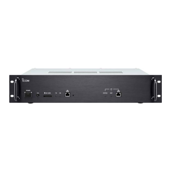
Page 7: Panel Description
Sets the output power to High (25 W) or Low (2.5 W). 8 LTE STATUS [STATUS]* Indicates the LTE status. (ID-RP2010V/ID-RP4010V) z Sets the output power to High (10 W) or Low (1.0 W). L About the LED indication (ID-RP1200VD) •... -
Page 8: Rear Panel
[CONT I/O]. L Turn the repeater OFF and then restart it to apply the change. 6 DV/DD SELECT SWITCH [DV/DD] This switch on the ID-RP2010V/ID-RP4010V does not work. 7 SERVICE JACK [SERVICE] (p. 16) Outputs the receive audio and DTMF tones. - Page 9 PANEL DESCRIPTION ID-RP1200VD: 1 CONT I/O PORT [CONT I/O] (p. 15) 9 TX ANTENNA CONNECTOR [TX ANT] (p. 16) Connects to the ID-RP2C with the supplied control Connects to a 50 Ω transmit antenna. cable for serial data communications. L In DD mode, the connector is used as a both TX and RX antenna connector.
-
Page 10: Installation And Connection
INSTALLATION AND CONNECTION ■ Select a location Select a location for the repeater that enables adequate air circulation, free from extreme heat, cold or vibration, and other electromagnetic sources. Never place the repeater in areas such as: • Temperatures below –10°C (+14°F) or above +50°C (+122°F). -
Page 11: Installing In A System Rack
INSTALLATION AND CONNECTION ■ Installing in a system rack This repeater is designed to be installed in a standard EIA 19-inch rack. NOTE: • Be sure to secure the repeater’s front panel to the system rack. • Use the rack that can hold the weight of approximately 6 kg (13.2 lbs). -
Page 12: Connecting The Utility Software
Connect the repeater and the Windows PC that the Utility for ID-RP3 is installed in, as shown below. To use the USB cable between the repeater and a PC, you must first install a USB driver. Download the latest USB driver and installation guide on the Icom website. https://www.icomjapan.com/support/... -
Page 13: Connecting Multiple Repeaters
Connect multiple repeaters using the supplied LAN NOTE: The repeaterʼs default ID is as follows: cable. This allows sharing one gateway server by ID-RP2010V: 1, ID-RP4010V: 2, ID-RP1200VD: 3 multiple repeaters for different bands. If two ID-RP1200VD repeaters, one for DV mode and L Up to 4 repeaters are connectable. -
Page 14: Operating As A Gateway
INSTALLATION AND CONNECTION ■ Operating as a Gateway D Using a Gateway server Connect the repeater, Gateway server, and router as shown below. Ask your dealer for details of settings required for the Gateway server and router. L Only one repeater can be used as a Gateway if multiple repeaters are connected. L If multiple repeaters are connected, and the ID-RP1200VD operating in DD mode is included, connect the gateway server to the ID-RP1200VD. -
Page 15: Sd Card
• The SD card has a certain lifetime. Data reading or writing may not be possible after using it for a long years. • Icom will not be responsible for any damage caused by data corruption on an SD card. -
Page 16: About The Sd Card's Folder Contents
SD CARD ■ About the SD card’s folder contents When inserting an SD card, folders will be created as shown below. You can browse or edit the contents on your PC. ID-RP3 Firmware Setting Speech Firmware folder: Saves the “dat” format firmware data when updating the repeaterʼs firmware. -
Page 17: Maintenance
The fuses are installed in the DC power cable and in the inside circuitry, to protect the repeater. • DC power cable fuses: ATC 25 A (ID-RP2010V) 2. Remove the shield screws and springs*, and then ATC 10 A (ID-RP4010V/ remove the shield cover. -
Page 18: About The Firmware
SD card (p. 11). Allen wrench Rack handle ■ Troubleshooting If the repeater seems to be not correctly operating, check the following points before sending it to an authorized Icom service center. PROBLEM POSSIBLE CAUSE SOLUTION REFERENCE The repeater does not turn •... -
Page 19: Information
± 2.5 kHz (FM narrow), ± 5.0 kHz (FM wide) • Occupied bandwidth: 6 kHz or less (DV), 150 kHz or less (DD) • Spurious emissions: Harmonics –63 dB or less (ID-RP2010V) –61.8 dB or less (ID-RP4010V) –53 dB or less (ID-RP1200VD) Out-of-band emission –60 dB or less (ID-RP2010V/ID-RP4010V) -
Page 20: D Receiver
INFORMATION ■ Specifications (Continued) D Receiver • Receive system: ID-RP2010V/ID-RP4010V RF direct sampling ID-RP1200VD Superheterodyne • Sensitivity: –15 dBµV (0.18 μV) or less (At 12 dB SINAD) –13 dBµV (0.22 μV) or less (At 1% BER (PN9)) DD (ID-RP1200VD) 4 dBµV (1.58 μV) or less (At 1% BER (PN9)) •... -
Page 21: D [Rpt1]/[Rpt2]
“daisy chained” together, and form a ■ About CE and DOC network that allows other data to pass among them. Hereby, Icom Inc. declares that the versions of ID-RP2010V/ID-RP4010V/ ID-RP1200VD which have the “CE” D [REF IN 10MHz] symbol on the product, comply with the... -
Page 22: Fcc Information
TV expérimenté. CAUTION: Changes or modifications to this device, MISE EN GARDE: Tout changement ou modification, not expressly approved by Icom Inc., could void non expressément approuvé par Icom Inc, peut your authority to operate this device under FCC annuler l’autorisation de l’utilisateur à utiliser cet regulations. - Page 23 MEMO...
- Page 24 How the world communicates A7595H-1EX-3 Printed in Japan 1-1-32 Kamiminami, Hirano-ku, Osaka 547-0003, Japan © 2020–2022 Icom Inc. Apr. 2022...
Need help?
Do you have a question about the ID-RP2010V and is the answer not in the manual?
Questions and answers