Table of Contents

Related Manuals for Icom ID-RP2C


Summary of Contents for Icom ID-RP2C
- Page 1 DIGITAL REPEATER SYSTEM id- rp2 Instruction Manual NOTE: This instruction manual is about the ID-RP2C with- out the assist function. If you are using the function, refer to the ID-RP2C instruction manual with the as- sist function.
-
Page 2: Important
R WARNING! NEVER apply more than 16 V DC to the disturbances, riots, war, or radioactive contamination. [DC 13.8V IN] connector on the repeater. This could cause • The use of Icom products with any equipment that is not a fire or damage the repeater. manufactured or approved by Icom. -
Page 3: Table Of Contents
FCC INFORMATION ..........ii 7 REPEATER SETTINGS ....... 21–26 1 SYSTEM OUTLINE ..........1 ■ ID-RP2C setting ..........21 D ID-RP2C utility screen ......... 22 ■ ID-RP2C............1 ■ ID-RP2D............1 ■ Frequency setting for ID-RP2D ....... 25 ■ ID-RP2V ............1 ■... -
Page 4: System Outline
ID-RP2V: 1.2 GHz digital voice repeater ➥ The ID-RP2D and ID-RP2V utility software, sup- In addition, the following options may also be required plied with the ID-RP2C, and a PC are required for for system repeater operations. both receive and transmit frequency settings. -
Page 5: Supplied Accessories
SUPPLIED ACCESSORIES ■ Accessories for ID-RP2C q Power cable .. 1 (OPC-1380; approximately. 3 m; 10 ft) w CD (USB driver, Utility software)......1 e Rubber feet ............4 r Spare fuses ........2 (FGB01 30A) ■ Accessories for ID-RP2D/ID-RP2V q Power cable ... -
Page 6: Panel Descriptions
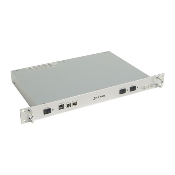
PANEL DESCRIPTIONS ■ ID-RP2C (Front panel) q POWER SWITCH [POWER] w 10BASE-T CONNECTOR [10BASE-T] (p. 24) Push to turn ON the power. Connects a PC with LAN cable to set the details of The LED indicator located at right lights when the the repeater site, such as the call sign, IP address. -
Page 7: Id-Rp2D (Front Panel)
(Rear panel) e r t q ANTENNA CONNECTOR [ANT] (p. 7) e POWER CONNECTOR [DC13.8V] (p. 7) Connect the optional AH-108 1.2 GHz Collinear Connects to the ID-RP2C with the supplied DC antenna. power cable to be supplied the DC (OPC-1309) power. -
Page 8: Id-Rp2V (Front Panel)
RECEIVE ANTENNA CONNECTOR [ANT] (p. 7) t [CONT I/O] (p. 7) Connect the optional AH-108 1.2 GHz Collinear Connects to the ID-RP2C with the supplied control antenna separately, or through a duplexer. cable for serial data communications. w TRANSMIT ANTENNA CONNECTOR [ANT] (p. 7) y GROUND TERMINAL [GND] (p. -
Page 9: Installing And Connecting
■ Attaching the rubber feet Use 50 Ω connectors and coaxial cable. For desktop installations, attach the supplied rubber Use “N” type connectors between the repeater and the feet onto the bottom of the ID-RP2C/D/V as shown antennas. below. • Cross section... -
Page 10: System Connections
INSTALLING AND CONNECTING ■ System connections AH-108* Antenna OPC-1380 filter (supplied w/ID-RP2C) ID-RP2C OPC-1309 (supplied w/ID-RP2D/V) ID-RP2V Duplexer Control cable (supplied w/ID-RP2D/V) OPC-1309 (supplied w/ID-RP2D/V) Coaxial cables External DC power (purchase separately) supply 13.8 V Black ID-RP2D Control cable (supplied w/ID-RP2D/V) *Not available in European countries as of November 2017. -
Page 11: Antenna Assembling
INSTALLING AND CONNECTING ■ Antenna assembling (Not available in European countries) D AH-108 q Attach the nut to the radial, then attach the ra- (M6) AH-108 dial to the AH-108. w Attach the supplied bolts, pole clamps, spring wash- Pole ers, flat washers and nuts to the AH-108 as illus- (30–60 mm) trated at left. -
Page 12: Driver Installations
“ ” is displayed, as shown • When installing the driver, log in as the administrator. below. w Insert the CD that is supplied with the ID-RP2C (Ap- NOTE: Although the warning symbol “ ” indicates that plication CD) into the CD drive. - Page 13 DRIVER INSTALLATIONS u Right-click on the device icon with the warning sym- !0 Select the “DRIVER” folder in the application CD, bol “ ,” and then click “Update Driver Software...” on or the unzip driver file (downloaded driver file), and the menu.
- Page 14 DRIVER INSTALLATIONS ■ Microsoft ® Windows ® 8.1— Continued !3 After the installation is completed, the “Windows has successfully updated your driver software” will appear. Click [Close]. Click !4 Again, right-click on the device icon with the warn- ing symbol “ ” in the “Device manager,” and then click “Update Driver Software...”...
-
Page 15: Microsoft ® Windows ® 7
“ ” is displayed, as shown • When installing the driver, log in as the administrator. below. w Insert the CD that is supplied with the ID-RP2C (Ap- NOTE: Although the warning symbol “ ” indicates that plication CD) into the CD drive. - Page 16 DRIVER INSTALLATIONS ■ Microsoft ® Windows ® 7— Continued !0 The “Browse for driver software on your computer” !3 When the Windows Security screen appears, click will appear. Click [Browse...]. [Install] to continue. Click Click !4 After the installation is completed, “Windows has successfully updated your driver software”...
-
Page 17: Checking The Com Port
• When opening the Device Manager, log in as the admin- Manager” screen to check the COM port number. istrator. • When the driver is completely installed, “ICOM ID-RP2D w Connect the PC and the ID-RP2D [SERVICE] con- SERVICE (COMM)” is displayed. The screen shows the nector with the USB cable. -
Page 18: D Microsoft Windows 7
• When opening the Device Manager, log in as the admin- Manager” screent o check the COM port number. istrator. • When the driver is completely installed, “ICOM ID-RP2D w Connect the PC and the ID-RP2D [SERVICE] con- SERVICE (COMM)” is displayed. The screen shows the USB serial COM port number “4.”... -
Page 19: Uninstalling The Usb Driver
Manager.” • The “Device Manager” window appears. r Double-click “Ports (COM&LPT)” on the “Device Manager” screen. • “ICOM ID-RP2D SERVICE (COMM)” appears. i Right-click “ICOM ID-RP2D SERVICE” and then click “Uninstall.” q Right-click w Click t Right-click “ICOM ID-RP2D SERVICE (COMM)”... -
Page 20: D Microsoft Windows 7
Click “Device Manager.” • The “Device Manager” window appears. t Double-click “Ports (COM&LPT)” on the “Device Manager” screen. • “ICOM ID-RP2D SERVICE (COMM)” appears. o Right-click “ICOM ID-RP2D SERVICE” and then click “Uninstall.” q Right-click w Click y Right-click “ICOM ID-RP2D SERVICE (COMM)”... -
Page 21: Installing The Utility Software
• Quit all other applications if any are running. • When uninstalling the driver, log in as the administrator. w Insert the CD that is supplied with the ID-RP2C (Ap- plication CD) into the CD drive. e Click “Computer” and then display the contents of the CD. - Page 22 INSTALLING THE UTILITY SOFTWARE ■ Installing— continued i The “Choose Destination Location” screen ap- NOTE: After installing the utility, the short cut icon pears. will automatically be created on the desktop. • When installing the Utility software at the displayed loca- When the icon looks like white square, right-click on tion, click [Next>].
-
Page 23: Uninstalling The Utility Software
The screen appears as shown below when the un- click “Uninstall a program.” installation starts. Click w Right-click the “Icom ID-RP2C,” then click “Uninstall/ Change”. t The screen appears as shown below when the un- installation is completed. Click [Finish]. -
Page 24: Repeater Settings
(patch connection) the ID-RP2C settings. The fixed IP address that can be communicated to the ID-RP2C must be set to the PC in advance. Refer to the instruction manual of the PC or LAN card for IP address setting details. -
Page 25: D Id-Rp2C Utility Screen
UDP port number entering for accessing the ID- DO NOT forget the both IP address and password RP2C appears. setting. The access to the ID-RP2C through the utility software will be impossible if forgotten. Enter the IP address of the ID-RP2C. - Page 26 Click to display the check mark, “4,” in the corre- The ID-RP2C boxed with this instruction manual sponding connector name. The names correspond cannot use this function. to [CONT I/O] connectors on the ID-RP2C rear panel ((1), (2), (3) and (4) from the left) !3 Always TX...
- Page 27 REPEATER SETTINGS !5 IP Address @2 Subnet Mask Enter the gateway IP address. Enter the subnet mask of the network if the re- peater is connected to the existing network (e.g., !6 Port (port number) LAN) Enter the gateway UDP port number. If a PC is connected, set the same subnet mask !7 Monitor (monitor usage) of the PC for the repeater and server (gateway or...
-
Page 28: Frequency Setting For Id-Rp2D
REPEATER SETTINGS ■ Frequency setting for ID-RP2D q Start up the PC. NOTE: The repeater unit connection may not be recog- w Connect a PC’s USB port and [SERVICE] connec- nized with the PC according to the using USB cable tor of the ID-RP2D with an A-B type USB cable length. -
Page 29: Frequency Setting For Id-Rp2V
REPEATER SETTINGS ■ Frequency setting for ID-RP2V q Start up the PC. NOTE: w Connect a PC’s USB port and the ID-RP2V [SER- The repeater unit connection may not be recog- VICE] connector with an A-B type USB cable (User nized with the PC according to the using USB cable , then turn the ID-RP2V power ON. -
Page 30: Maintenance
MAINTENANCE ■ Troubleshooting If your repeater seems is not operating correctly, check the following points before sending it to an au- thorized Icom service center. PROBLEM POSSIBLE CAUSE SOLUTION REF. Does not turn ON. • Power connector has a poor contact. -
Page 31: Cleaning
MAINTENANCE ■ Cleaning DO NOT use harsh solvents such as benzine or alco- hol when cleaning, as they can damage the repeater’s surfaces. ■ Replacing fuses If the fuse blows or the repeater stops functioning, find the source of the problem, repair it, and then replace the damaged fuse with a new, rated one as shown below. -
Page 32: Specifications And Options
SPECIFICATIONS AND OPTIONS ■ Specifications D ID-RP2C • General Power supply requirement: 13.8 V DC ±15% (negative ground) Current drain: Less than 0.5 A Usable temperature range: –10˚C to +50˚C; +14˚F to +122˚F Dimensions 483(W)×44(H)×257(D) mm; 19.0(W)×1.7(H)×10.1(D) inches (approximately) (projections not included) Weight 2.7 kg;... -
Page 33: D Id-Rp2D/Id-Rp2V
SPECIFICATIONS AND OPTIONS D ID-RP2D/ID-RP2V ID-RP2D ID-RP2V Receive 1240 to 1300 MHz Frequency range Transmit 1240 to 1300 MHz F1D (GMSK) Type of emission F1D (GMSK) *F7W for system operation Frequency stability ±2.5 ppm (based on 25˚C; +77˚F) Frequency resolutions 5/6.25 kHz Antenna connector N type... -
Page 34: Information
INFORMATION ■ About CE and DOC ■ Country code list Hereby, Icom Inc. declares that the ver- • List of Country codes ( ISO 3166-1) sions of ID-RP2C which have the “CE” Country Codes Country Codes symbol on the product, comply with the... - Page 35 MEMO...
- Page 36 ■ PL ■ PT ■ SK ■ SI ■ ES ■ SE ■ GB ■ IS ■ LI ■ NO ■ CH ■ BG ■ RO ■ TR ■ HR A7226H-1EX-1 Printed in Japan 1-1-32 Kamiminami, Hirano-ku, Osaka 547-0003, Japan © 2015–2017 Icom Inc.
Need help?
Do you have a question about the ID-RP2C and is the answer not in the manual?
Questions and answers