Table of Contents
Advertisement
Quick Links
UHF DIGITAL VOICE REPEATER
id- rp4000v
Instruction Manual
This device complies with Part 15 of the FCC rules. Operation
is subject to the following two conditions: (1) This device may
not cause harmful interference, and (2) this device must accept
any interference received, including interference that may cause
undesired operation.
Advertisement
Table of Contents

Related Manuals for Icom id- rp4000v


Summary of Contents for Icom id- rp4000v
- Page 1 UHF DIGITAL VOICE REPEATER id- rp4000v Instruction Manual This device complies with Part 15 of the FCC rules. Operation is subject to the following two conditions: (1) This device may not cause harmful interference, and (2) this device must accept any interference received, including interference that may cause undesired operation.
-
Page 2: Important
ID- Icom, Icom Inc. and the Icom logo are registered trade- RP4000V. This may result in an electric shock. marks of Icom Incorporated (Japan) in Japan, the United... -
Page 3: Table Of Contents
FOR CLASS B UNINTENTIONAL RADIATORS This equipment has been tested and found to comply with If this equipment does cause harmful interference to radio the limits for a Class B digital device, pursuant to part 15 or television reception, which can be determined by turn- of the FCC Rules. -
Page 4: System Outline
SYSTEM OUTLINE n ID-RP4000V The ID-RP4000V is installed into the Digital Smart Technologies for Amateur Radio (D-STAR) repeater system for operation. • ID-RP4000V is a 440 MHz digital voice and slow- The ID-RP4000V never functions as a repeater with- speed data repeater and connects to the (4.8 kbps) out ID-RP2C, due to no relay function is built-in. -
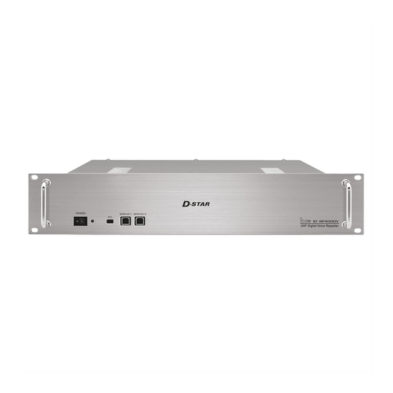
Page 5: Panel Descriptions
PANEL DESCRIPTIONS n Front panel q w e r t r SERVICE CONNECTOR T [SERVICE T] (p. 30) q POWER SWITCH [POWER] Connect a PC via a USB cable The power switch for ID-RP4000V. (A-B type; purchase to set the transmit frequency. separately) w POWER INDICATOR t SERVICE CONNECTOR R [SERVICE R] (p. -
Page 6: Connections And Installations
CONNECTIONS AND INSTALLATIONS n Precautions R WARNING! NEVER connect the ID-RP4000V to a power source using reverse polarity. This will dam- age the ID-RP4000V. Make sure the ID-RP4000V’s power is turned OFF when connecting a DC power cable. CAUTION: NEVER expose the ID-RP4000V to rain, snow or any liquids. -
Page 7: When Install Into System Rack
CONNECTIONS AND INSTALLATIONS n When install into system rack The ID-RP4000V is designed to install into a standard EIA 19-inch rack. Use the supplied bolts with the rack when fixing the ID-RP4000V. We recommend to use the rack that has rails be- cause the weigh of the ID-RP4000V is approx. -
Page 8: System Connections
CONNECTIONS AND INSTALLATIONS n System connections ID-RP2L* 430/440 MHz ID-RP2L* band antenna (Assist 2) (Assist 1) (purchase separately) to AH-106*/107* to AH-106*/107* OPC-1380 (supplied w/ID-RP2C) ID-RP2C OPC-1309 Duplexer (supplied w/ID-RP4000V) ID-RP4000V (purchase separately) External DC power Control cable supply 13.8 V (supplied w/ID-RP4000V) Black Coaxial cables... -
Page 9: Driver Installations
DRIVER INSTALLATIONS The USB cable (Universal Serial Bus) (A-B type; purchase is used for the connection between ID- separately) RP4000V and a PC. So, the USB driver installation is required for the PC. In addition, individual USB driver installation is re- quired for each connector, because the communica- tion port number difference. - Page 10 DRIVER INSTALLATIONS n Microsoft ® Windows ® XP (Service Pack 2)— continued y When the dialog box as at left is displayed, se- lect “Install the software automatically (Recom- mended),” then click [Next>]. Select Click u The wizard starts searching for the driver and shows the dialog as at left during search.
- Page 11 DRIVER INSTALLATIONS o Windows starts installing the USB driver. !0 After the installation is completed, click [Finish]. Click !1 After clicking [Finish], “Found New Hardware USB Serial Port” appears as at left. !2 The “Found New Hardware Wizard” will come up as at left.
- Page 12 DRIVER INSTALLATIONS ® ® n Microsoft Windows XP (Service Pack 2)— continued !3 Select “Install the software automatically (Recom- mended),” then click [Next>]. Select Click !4 The wizard starts searching for the driver and shows the dialog as at left during search. !5 While searching the driver, the “Hardware Installa- tion”...
- Page 13 DRIVER INSTALLATIONS !6 Windows starts installing the USB driver. !7 After the installation is completed, click [Finish]. Click !8 After clicking [Finish], “Found New Hardware Your new hardware is installed and ready to use” ap- pears as at left. !9 Eject the CD. •...
-
Page 14: Microsoft Windows ® 2000
DRIVER INSTALLATIONS n Microsoft ® Windows ® 2000 q Start up Windows. • Quit all applications if activated. w Insert the CD supplied with the ID-RP4000V, into the CD drive. e Connect the PC and ID-RP4000V [SERVICE T] connector using with a USB cable (A-B type;... - Page 15 DRIVER INSTALLATIONS u Select “CD-ROM drives,” then click [Next >]. Select Click i When the appropriate driver is found, the dialog box appears as at left appears. Click [Next >] to start the installation. Click o After the installation is completed, click [Finish]. Click !0 After clicking [Finish], “Found New Hardware USB Serial Port”...
- Page 16 DRIVER INSTALLATIONS n Microsoft ® Windows ® 2000— continued !1 The “Found New Hardware Wizard” will come up as at left. Click [Next->]. Click !2 Select “Search for a suitable driver for my device (recommended),” then click [Next->]. Select Click !3 Select “CD-ROM drives,”...
- Page 17 DRIVER INSTALLATIONS !4 When the appropriate driver is found, the dialog box appears as at left appears. Click [Next >] to start the installation. Click !5 After the installation is completed, click [Finish]. !6 Eject the CD. • Rebooting the PC is recommended. Click...
-
Page 18: Microsoft Windows ® 98Se/Me
DRIVER INSTALLATIONS n Microsoft ® Windows ® 98SE/Me q Start up Windows. • Quit all applications if activated. w Insert the CD supplied with the ID-RP4000V, into the CD drive. e Connect the PC and ID-RP4000V [SERVICE T] connector using with a USB cable (A-B type;... - Page 19 DRIVER INSTALLATIONS u Double-click the “Dr iver” folder then select “WinME98” folder in the CD. Click [OK]. Select Click i Confirm the driver folder in the CD is selected, then click [Next >]. Confirm Click o When the driver is found, the screen as at left ap- pears.
-
Page 20: N Microsoft ® Windows ® 98Se/Me
Microsoft ® Windows ® 98SE/Me— continued !0 After the installation is completed, click [Finish]. Click !1 After clicking [Finish], “New Hardware Found ICOM ID-RP4000V SERVICE T” appears as at left. !2 Eject the CD. • Rebooting the PC is recommended. -
Page 21: Microsoft Windows Vista
DRIVER INSTALLATIONS n Microsoft ® Windows Vista ® When the PC can be connected to the Internet, please make the PC stand-alone. q Start up Windows. • Quit all applications if activated. w Insert the CD that comes with the ID-RP4000V, into the CD drive. - Page 22 DRIVER INSTALLATION n Microsoft ® Windows Vista ® — continued u The dialog box as at left is displayed. Click “Install this driver software anyway” to start the installation. Click i The wizard starts searching for the driver and shows the dialog as at left during search. o After the installation is completed, click [Close].
- Page 23 DRIVER INSTALLATIONS !0 When the “Found New Hardware -USB Serial Port” appears as at left, click [Next]. Click !1 The dialog box as at left is displayed. Click “Install this driver software anyway” to start the installation. Click !2 The wizard starts searching for the driver and shows the dialog as at left during search.
- Page 24 DRIVER INSTALLATION n Microsoft ® Windows Vista ® — continued !3 After the installation is completed, click [Close]. !4 Eject the CD. • Rebooting the PC is recommended. Click...
-
Page 25: Com Port Confirmation
“Device Manager” screen appears. Click “ ” of Ports (COM&LPT). Click y Confirm “ICOM ID-RP4000V SERVICE T (COMQ)” is displayed. • If not displayed, or few COM port numbers are dis- played at the same time, the driver installation may not be installed properly. -
Page 26: D Microsoft ® Windows ® 98Se/Me
Click t Click “ ” of Ports (COM&LPT). Click y Confirm “ICOM ID-RP4000V SERVICE T (COMQ)” is displayed. • If not displayed, or few COM port numbers are dis- played at the same time, the driver installation may not be installed properly. Un-install the USB driver then re- install the driver again in such cases. -
Page 27: D Microsoft ® Windows Vista
“Device Manager” screen appears. Click “ ” of Ports (COM&LPT). Confirm “ICOM ID-RP4000V SERVICE T (COMQ)” is displayed. • If not displayed, or few COM port numbers are dis- played at the same time, the driver installation may not Click be installed properly. -
Page 28: Usb Driver Un-Installation
DRIVER INSTALLATION n USB driver un-installation Un-install the USB drivers as follows. IMPORTANT! In this section, describes the un-installation instruc- As described at first of this section, USB driver is in- ® ® tion with Microsoft Windows XP for example. stalled for each unit and connector. -
Page 29: Driver Installations
Click to add the check mark, “4,” into “Delete the driver software for this device.” then click [OK]. Click y Right click the “ICOM ID-RP4000V SERVICEQ” , then select “Uninstall”. Click u Click to add the check mark, “4,” into “Delete the driver software for this device.”... -
Page 30: Utility Installation
UTILITY INSTALLATION The utility is used for the setting of call sign and oper- ating frequencies. This section is based on using Microsoft ® Win- dows ® XP. The displayed screens, indications or operations may differ slightly from the instructions, depending on your system configuration or Win- dows operating system. - Page 31 UTILITY INSTALLATION o “Choose Destination Location” screen appears. • When installing the utility into the displayed location, click [Next>]. • When installing into a different location, click [Browse…], select the desired location and then click [Next>]. Click !0 Starts the utility installation. !1 “InstallShield Wizard Complete”...
-
Page 32: Un-Installation
OS, “Add and Remove Programs,” as follows. q Open “Control Panel” in the Start menu. w Click “Add or Remove Programs.” Click e Select “Icom ID-RP4000V,” then click [Change/Re- move]. Select Click r “Confirm Uninstall” screen appears, click [OK]. -
Page 33: Repeater Settings
REPEATER SETTINGS n Frequency setting for ID-RP4000V q Start up the PC. NOTE: w Connect a USB cable (A-B type; purchase separately) The ID-RP4000V connection may not be recog- between PC’s USB port and ID-RP4000V [SER- nized by the PC depending on the length of the VICE T] or [SERVICE R] connector, then turn the USB cable. -
Page 34: Maintenance
MAINTENANCE n Troubleshooting If your ID-RP4000V seems to be malfunctioning, please check the following points before sending it to a service center. PROBLEM POSSIBLE CAUSE SOLUTION REF. Does not turn ON. • Power connector has a poor contact. • Check the connector pins and re-connect the p. -
Page 35: Specifications And System Units
SPECIFICATIONS AND SYSTEM UNITS n Specifications D General • Frequency range U.S.A. Tx/Rx 440 to 450 MHz Europe Tx/Rx 430 to 440 MHz • Type of emission : F1D (GMSK; F7W for system operation) • Frequency stability : ±0.8 kHz (based on 25˚C;... -
Page 36: About Ce
ABOUT CE DECLARATION OF CONFORMITY We Icom Inc. Japan 1-1-32, Kamiminami, Hirano-ku Osaka 547-0003, Japan Declare on our sole responsibility that this equipment complies with the essential requirements of the Radio and Telecommunications Terminal Bad Soden 14th May 2010 Equipment Directive, 1999/5/EC, and that any applicable Essential Test Place and date of issue Suite measurements have been performed. - Page 40 #31 (Europe) <Intended Country of Use> A-6448H-1EX-e Printed in Japan 1-1-32 Kamiminami, Hirano-ku, Osaka 547-0003, Japan © 2006–2010 Icom Inc.
Need help?
Do you have a question about the id- rp4000v and is the answer not in the manual?
Questions and answers