Icom ic-FR4000 Instruction Manual
Uhf fm repeater
Hide thumbs
Also See for ic-FR4000:
- Service manual (79 pages) ,
- Price list (158 pages) ,
- Sales handbook (74 pages)
Table of Contents
Advertisement
Quick Links
Advertisement
Table of Contents

Subscribe to Our Youtube Channel
Related Manuals for Icom ic-FR4000


Summary of Contents for Icom ic-FR4000
- Page 1 INSTRUCTION MANUAL UHF FM REPEATER iFR4000...
-
Page 2: Important
R NEVER facturer’s microphones have different pin assignments, apply more than 16 V DC, such as a 24 V and connection to the IC-FR4000 may damage the re- battery, to the [BATTERY] terminals on the repeater peater. rear panel. This could cause a fire or damage the re- peater. -
Page 3: Table Of Contents
We want to take a couple of moments of your time to e Spare fuses (ATC 20) ……………………………… 2 thank you for making the IC-FR4000 your repeater of choice, and hope you agree with Icom’s philosophy of “technology first.” Many hours of research and devel- opment went into the design of your IC-FR4000 series. -
Page 4: Panel Description
This 8-pin modular jack accepts the optional micro- only, select a repeater operating mode. phone. • When using IC-FR4000 as full (or half) duplex trans- ceiver or setting up a repeater system connecting an ex- q +9 V DC output (Max. 10 mA) ternal controller, select a base operating mode. -
Page 5: I Rear Panel
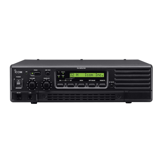
PANEL DESCRIPTION !6 ANI CLEAR SWITCH [ANI CLR] D D Function display ➥Push momentarily to turn OFF the alert tone when receiving a call with ANI code. 32HH@HICOMHINC. ➥Push for 1 sec. to clear the received ANI ID indi- cation on the display and returns to original indi- cation. -
Page 6: D Accessory Connector
PANEL DESCRIPTION D REMOTE CONNECTOR Pin No. Pin Name Description Specification Input terminals to transmit the repeater in rela- –PTT High voltage=PTT ON (transmits) tion to the external equipment. An opto-isolator Hi-Z=PTT OFF is provided to facilitate PTT signals. +PTT Output terminal for AF signals from the AF de- –AFOUT Output impedance: 600 Ω... - Page 7 PANEL DESCRIPTION ACCESSORY CONNECTOR (continued) Pin No. Pin Name Description Specification M/S OUT Output terminal for master/slave signal. Open collector=OFF, 0V=ON Input terminal for selecting memory channel. +5 V pull up, Active=L Input terminal for selecting memory channel. +5 V pull up, Active=L Input terminal for selecting memory channel.
-
Page 8: Installation And Connections
For a description and a diagram of accessory equip- ceiving frequencies. Ask your Dealer for details. ment included with the IC-FR4000, see ‘Supplied ac- cessories’ on p. ii of this manual. I Grounding... -
Page 9: I Required Connections
CAUTION: DO NOT short pin 1 to ground as this can damage the internal 9 V regulator. DC voltage is applied to pin 1 for microphone operation. Take care when using a non-Icom microphone. [DC POWER INPUT TERMINAL] (p. 8) + red... -
Page 10: I Advanced Connections
INSTALLATION AND CONNECTIONS I Advanced connections LINE CONNECTOR (Front panel view) q NC (No connection) w L1 input/output e L2 input/output r NC (No connection) * This illustration is example only. Telephone connector type is different for some countries. EXTERNAL SPEAKER Use a 4 Ω... -
Page 11: I Power
(emergency power supply). available for mounting the repeater into a 19 inch rack. The IC-FR4000 series can operate with an AC or DC The MB-78 can install the repeater’s bottom side and power supply. If AC power is interrupted when operat- top side. - Page 12 INSTALLATION AND CONNECTIONS • Top side installation q Remove the 1 screw (M4 × 8) from both side of the t Remove the 2 screws (M4 × 8) from both side of MB-78. the side panel (front-end). w Remove the handles from bottom bar. And turn the y Attach the MB-78 to the top side of the repeater.
- Page 13 INSTALLATION AND CONNECTIONS D Using the optional MB-77 • Mount the MB-77 securely with the 12 supplied An optional MB-77 is available WALL MOUNT BRACKET screws (M6 × 30) to a surface which is more than 50 for mounting the repeater to a flat surface. mm thick and can support more than 20 kg.
-
Page 14: Optional Unit Installation
OPTIONAL UNIT INSTALLATION I Opening the repeater’s case Follow the case and cover opening procedures shown here when an optional unit is installed or adjust the in- ternal units, etc. CAUTION: DISCONNECT the AC power cable and/or DC power cable from the repeater. Other- wise, there is danger of electric shock and/or equip- ment damage. -
Page 15: Operation
If the repeater is programmed for a power on pass- q Push [POWER] to turn power OFF, if repeater word by an Icom Dealer, input digit codes directly. power is ON. w While pushing [PROG], [ANI CLR] and [DN], turn •... -
Page 16: Maintenance
The following chart is designed to help correct prob- If you are unable to locate the cause of a problem or lems which are not equipment malfunctions. solve it through the use of this chart, contact the near- est Icom Dealer or Service Center. PROBLEM POSSIBLE CAUSE SOLUTION REF. -
Page 17: I Fuse Replacement
MAINTENANCE I Fuse replacement If a fuse blows or the repeater stops functioning, try to CAUTION: DISCONNECT the AC power cable find the source of the problem, and replace the dam- and/or DC power cable from the repeater. Other- aged fuse with a new, rated fuse. wise, there is danger of electric shock and/or equip- ment damage. -
Page 18: Specifications And Options
SPECIFICATIONS AND OPTIONS I Specifications I Options Specifications are measured in accordance with EIA/TIA-603. • MB-77 WALL MOUNT BRACKET (p. 10) D D General For mounting the repeater to a wall. • Frequency coverage : 400.000–430.000 MHz • MB-78 19 INCH RACK MOUNT BRACKET (pgs. 9, 10) 430.000–450.000 MHz For mounting the repeater into a 19 inch rack. - Page 19 MEMO...
- Page 20 Count on us! A-6228H-1EX Printed in Japan 1-1-32 Kamiminami, Hirano-ku, Osaka 547-0003 Japan © 2003 Icom Inc.
Need help?
Do you have a question about the ic-FR4000 and is the answer not in the manual?
Questions and answers
what does it cost to download this manual for the IC-FR4000-3