Table of Contents
Advertisement
Quick Links
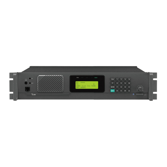
INSTRUCTION MANUAL
VHF P25 REPEATER
iFR9010
UHF P25 REPEATER
iFR9020
This device complies with Part 15 of the FCC Rules. Operation
is subject to the condition that this device does not cause harm-
ful interference.
American Communication Systems
Discover the Power of Communications
TO ORDER – VISIT
http://www.ameradio.com
™
Advertisement
Table of Contents


Need help?
Do you have a question about the FR9020 11 and is the answer not in the manual?
Questions and answers