Table of Contents
Advertisement
Quick Links
Advertisement
Chapters
Table of Contents

Subscribe to Our Youtube Channel
Related Manuals for Epson S1D13505F00A


Summary of Contents for Epson S1D13505F00A
- Page 1 S1D13505F00A Technical Manual Arrow.com. Downloaded from...
- Page 2 Seiko Epson. Seiko Epson reserves the right to make changes to this material without notice. Seiko Epson does not assume any liability of any kind arising out of any inaccuracies contained in this material or due to its application or use in any product or circuit and, further, there is no representation that this material is applicable to products requiring high level reliability, such as medical products.
- Page 3 The information of the product number change Starting April 1, 2001, the product number will be changed as listed below. To order from April 1, 2001 please use the new product number. For further information, please contact Epson sales representative.
- Page 4 TOBIRA.fm Page 1 Sunday, April 15, 2001 6:24 PM S1D13505F00A Technical Manual HARDWARE FUNCTIONAL SPECIFICATION PROGRAMMING NOTES AND EXAMPLES UTILITIES S5U13505P00C ISA BUS EVALUATION BOARD USER’S MANUAL APPLICATION NOTES ® WINDOWS CE DISPLAY DRIVERS Arrow.com. Arrow.com. Arrow.com. Arrow.com. Downloaded from...
- Page 5 Arrow.com. Arrow.com. Arrow.com. Arrow.com. Arrow.com. Downloaded from Downloaded from Downloaded from Downloaded from Downloaded from...
-
Page 6: Table Of Contents
PC Card Interface Timing ......................1-34 Generic Interface Timing......................1-36 MIPS/ISA Interface Timing.......................1-38 Philips Interface Timing (e.g. PR31500/PR31700) ..............1-40 Toshiba Interface Timing (e.g. TX3912) ..................1-42 PowerPC Interface Timing (e.g. MPC8xx, MC68040, Coldfire) ..........1-45 EPSON S1D13505F00A HARDWARE FUNCTIONAL SPECIFICATION (X23A-A-001-12) Arrow.com. Arrow.com. Arrow.com. Arrow.com. Arrow.com. - Page 7 4 Bit-Per-Pixel Color Mode....................1-110 8 Bit-Per-Pixel Color Mode....................1-111 12 I ....................1-113 URSOR RCHITECTURE 12.1 Ink/Cursor Buffers ........................1-113 12.2 Ink/Cursor Data Format ......................1-113 1-ii EPSON S1D13505F00A HARDWARE FUNCTIONAL SPECIFICATION (X23A-A-001-12) Arrow.com. Arrow.com. Arrow.com. Arrow.com. Arrow.com. Arrow.com. Arrow.com. Downloaded from Downloaded from...
- Page 8 14.1 Maximum MCLK: PCLK Ratios ....................1-119 14.2 Frame Rate Calculation......................1-120 14.3 Bandwidth Calculation .......................1-122 15 P ......................1-125 OWER ODES 16 M ......................1-126 ECHANICAL 1-iii EPSON S1D13505F00A HARDWARE FUNCTIONAL SPECIFICATION (X23A-A-001-12) Arrow.com. Arrow.com. Arrow.com. Arrow.com. Arrow.com. Arrow.com. Arrow.com. Arrow.com. Downloaded from Downloaded from...
- Page 9 8-Bit Single Color Passive LCD Panel A.C. Timing (Format 2).......... 1-66 Figure 7-34 16-Bit Single Color Passive LCD Panel Timing ..............1-67 Figure 7-35 16-Bit Single Color Passive LCD Panel A.C. Timing ............1-68 1-iv EPSON S1D13505F00A HARDWARE FUNCTIONAL SPECIFICATION (X23A-A-001-12) Arrow.com. Arrow.com. Arrow.com. Arrow.com. Arrow.com.
- Page 10 Ink/Cursor Data Format....................1-113 Figure 12-2 Cursor Positioning ......................1-114 Figure 13-1 Relationship Between the Screen Image and the Image Residing in the Display Buffer .1-115 Figure 16-1 Mechanical Drawing QFP15.....................1-126 EPSON S1D13505F00A HARDWARE FUNCTIONAL SPECIFICATION (X23A-A-001-12) Arrow.com. Arrow.com. Arrow.com. Arrow.com. Arrow.com. Arrow.com.
- Page 11 Panel Data Width Selection ....................1-81 Table 8-4 FPLINE Polarity Selection....................1-83 Table 8-5 FPFRAME Polarity Selection ..................... 1-85 Table 8-6 Simultaneous Display Option Selection ................1-86 1-vi EPSON S1D13505F00A HARDWARE FUNCTIONAL SPECIFICATION (X23A-A-001-12) Arrow.com. Arrow.com. Arrow.com. Arrow.com. Arrow.com. Arrow.com. Arrow.com.
- Page 12 Total # MCLKs Taken for Display Refresh ...............1-123 Table 14-6 Theoretical Maximum Bandwidth M byte/sec, Cursor/Ink Disabled .........1-124 Table 15-1 Power Save Mode Function Summary................1-125 Table 15-2 Pin States in Power-Save Modes..................1-125 1-vii EPSON S1D13505F00A HARDWARE FUNCTIONAL SPECIFICATION (X23A-A-001-12) Arrow.com. Arrow.com. Arrow.com. Arrow.com. Arrow.com. Arrow.com. Arrow.com.
-
Page 13: Introduction
Hardware Cursor, Ink Layer, and the Memory Enhancement Registers offer substantial performance benefits. These features, combined with the S1D13505’s Operating System independence, make it an ideal display solution for a wide variety of applications. EPSON S1D13505F00A HARDWARE FUNCTIONAL SPECIFICATION (X23A-A-001-12) Arrow.com. Arrow.com. -
Page 14: Features
- 8/16-bit interface to 8/16/32-bit MC68030 microprocessors/microcontrollers. - Philips PR31500/PR31700 (MIPS). - Toshiba TX3912 (MIPS). - Philips PR31500/PR31700. - 16-bit Power PC (MPC821) microprocessor. - 16-bit Epson E0C33 microprocessor. - PC Card (PCMCIA). - StrongARM (PC Card). - NEC VR41xx (MIPS). - ISA bus. -
Page 15: Display Modes
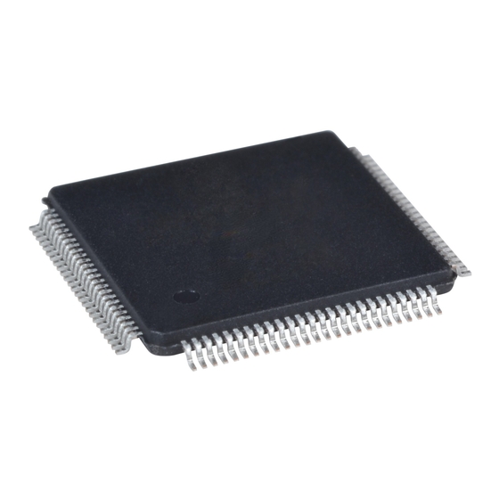
Output that can be used to control the LCD backlight. Power-on polarity is selected by an MD configuration pin. • Operating voltages from 2.7 volts to 5.5 volts are supported • 128-pin QFP15 surface mount package EPSON S1D13505F00A HARDWARE FUNCTIONAL SPECIFICATION (X23A-A-001-12) Arrow.com. Arrow.com. Arrow.com. -
Page 16: Figure 3-1 Typical System Diagram (Sh-4 Bus, 256Kx16 Fpm/Edo-Dram)
HRTC WAIT# Display VRTC CKIO BUSCLK RESET# RESET# IREF IREF 256Kx16 FPM/EDO-DRAM Figure 3-2 Typical System Diagram (SH-3 Bus, 256Kx16 FPM/EDO-DRAM) EPSON S1D13505F00A HARDWARE FUNCTIONAL SPECIFICATION (X23A-A-001-12) Arrow.com. Arrow.com. Arrow.com. Arrow.com. Arrow.com. Arrow.com. Arrow.com. Arrow.com. Arrow.com. Arrow.com. Arrow.com. Arrow.com. Arrow.com. -
Page 17: Figure 3-3 Typical System Diagram (Mc68K Bus 1, 16-Bit 68000, 256Kx16 Fpm/Edo-Dram)
WAIT# Display VRTC BCLK BUSCLK RESET# IREF RESET# IREF 256Kx16 FPM/EDO-DRAM Figure 3-4 Typical System Diagram (MC68K Bus 2, 32-Bit 68030, 256Kx16 FPM/EDO-DRAM) EPSON S1D13505F00A HARDWARE FUNCTIONAL SPECIFICATION (X23A-A-001-12) Arrow.com. Arrow.com. Arrow.com. Arrow.com. Arrow.com. Arrow.com. Arrow.com. Arrow.com. Arrow.com. Arrow.com. Arrow.com. -
Page 18: Figure 3-5 Typical System Diagram (Generic Bus, 1Mx16 Fpm/Edo-Dram)
WAIT# VRTC BCLK BUSCLK RESET IREF RESET# IREF 1Mx16 FPM/EDO-DRAM Figure 3-6 Typical System Diagram (NEC V 41xx (MIPS) Bus, 1Mx16 FPM/EDO-DRAM) EPSON S1D13505F00A HARDWARE FUNCTIONAL SPECIFICATION (X23A-A-001-12) Arrow.com. Arrow.com. Arrow.com. Arrow.com. Arrow.com. Arrow.com. Arrow.com. Arrow.com. Arrow.com. Arrow.com. Arrow.com. Arrow.com. -
Page 19: Figure 3-7 Typical System Diagram (Philips Pr31500/Pr31700 Bus, 1Mx16 Fpm/Edo-Dram)
Display VRTC CARDxWAIT* WAIT# DCLKOUT BUSCLK RESET# RESET# IREF IREF 1Mx16 FPM/EDO-DRAM Figure 3-8 Typical System Diagram (Toshiba TX3912 Bus, 1Mx16 FPM/EDO-DRAM) EPSON S1D13505F00A HARDWARE FUNCTIONAL SPECIFICATION (X23A-A-001-12) Arrow.com. Arrow.com. Arrow.com. Arrow.com. Arrow.com. Arrow.com. Arrow.com. Arrow.com. Arrow.com. Arrow.com. Arrow.com. Arrow.com. -
Page 20: Figure 3-9 Typical System Diagram (Power Pc Bus, 256Kx16 Fpm/Edo-Dram)
HRTC Display VRTC BCLK BUSCLK RESET# RESET# IREF IREF 1Mx16 FPM/EDO-DRAM Figure 3-10 Typical System Diagram (PC Card (PCMCIA) Bus, 1Mx16 FPM/EDO-DRAM) EPSON S1D13505F00A HARDWARE FUNCTIONAL SPECIFICATION (X23A-A-001-12) Arrow.com. Arrow.com. Arrow.com. Arrow.com. Arrow.com. Arrow.com. Arrow.com. Arrow.com. Arrow.com. Arrow.com. Arrow.com. Arrow.com. -
Page 21: Internal Description
16-bit memory devices (FPM- DRAM or EDO-DRAM). Display FIFO The Display FIFO block fetches display data from the Memory Controller for display refresh. EPSON S1D13505F00A HARDWARE FUNCTIONAL SPECIFICATION (X23A-A-001-12) Arrow.com. Arrow.com. Arrow.com. -
Page 22: Cursor Fifo
The DAC is the Digital to Analog converter for analog CRT support. Power Save The Power Save block contains the power save mode circuitry. Clocks The Clocks module is the source of all clocks in the chip. 1-10 EPSON S1D13505F00A HARDWARE FUNCTIONAL SPECIFICATION (X23A-A-001-12) Arrow.com. Arrow.com. Arrow.com. Arrow.com. Arrow.com. -
Page 23: Pins
AB14 MD10 AB13 AB12 MD11 AB11 AB10 MD12 MD13 MD14 MD15 Figure 5-1 Pinout Diagram 128-pin QFP15 surface mount package 1-11 EPSON S1D13505F00A HARDWARE FUNCTIONAL SPECIFICATION (X23A-A-001-12) Arrow.com. Arrow.com. Arrow.com. Arrow.com. Arrow.com. Arrow.com. Arrow.com. Arrow.com. Arrow.com. Arrow.com. Arrow.com. Arrow.com. Arrow.com. -
Page 24: Pin Description
5V/3.3V respectively), x denotes driver type (see tables 6-3, 6-4, 6-5 for details) = CMOS low-noise output driver, x denotes driver type (see tables 6-3, 6-4, 6-5 for details) 1-12 EPSON S1D13505F00A HARDWARE FUNCTIONAL SPECIFICATION (X23A-A-001-12) Arrow.com. Arrow.com. Arrow.com. -
Page 25: Host Interface
• For all other busses, this pin inputs the system address bit 19 (A19). See “Table 5-7 CPU Interface Pin Mapping” for summary. See the respec- tive AC Timing diagram for detailed functionality. 1-13 EPSON S1D13505F00A HARDWARE FUNCTIONAL SPECIFICATION (X23A-A-001-12) Arrow.com. Arrow.com. Arrow.com. - Page 26 • For all busses, this is the Chip Select input. See “Table 5-7 CPU Interface Pin Mapping” on page 1-20. See the respec- tive AC Timing diagram for detailed functionality. 1-14 EPSON S1D13505F00A HARDWARE FUNCTIONAL SPECIFICATION (X23A-A-001-12) Arrow.com. Arrow.com. Arrow.com.
- Page 27 • For PC Card (PCMCIA) Bus, this pin inputs the output enable signal (-OE). See “Table 5-7 CPU Interface Pin Mapping” for summary. See the respec- tive AC Timing diagram for detailed functionality. 1-15 EPSON S1D13505F00A HARDWARE FUNCTIONAL SPECIFICATION (X23A-A-001-12) Arrow.com. Arrow.com. Arrow.com.
- Page 28 Active low input that clears all internal registers and forces all outputs to RESET# – their inactive states. Note that active high RESET signals must be inverted before input to this pin. 1-16 EPSON S1D13505F00A HARDWARE FUNCTIONAL SPECIFICATION (X23A-A-001-12) Arrow.com. Arrow.com. Arrow.com. Arrow.com. Arrow.com.
-
Page 29: Memory Interface
Note that unless configured otherwise, this pin defaults to an input and must be driven to a valid logic level. See “Table 5-8 Memory Interface Pin Mapping” for summary. See Mem- ory Interface Timing for detailed functionality. 1-17 EPSON S1D13505F00A HARDWARE FUNCTIONAL SPECIFICATION (X23A-A-001-12) Arrow.com. Arrow.com. Arrow.com. Arrow.com. -
Page 30: Lcd Interface
BLUE Analog output for CRT color Blue Current reference for DAC - see Analog Pins. This pin must be left IREF unconnected if the DAC is not needed. 1-18 EPSON S1D13505F00A HARDWARE FUNCTIONAL SPECIFICATION (X23A-A-001-12) Arrow.com. Arrow.com. Arrow.com. Arrow.com. Arrow.com. -
Page 31: Miscellaneous
12, 33, 55, 72, 97, 109 99, 102, DAC V DACV 14, 32, 50, 68, 78, 87, 96, 110 DACV 98, 106 DAC V 1-19 EPSON S1D13505F00A HARDWARE FUNCTIONAL SPECIFICATION (X23A-A-001-12) Arrow.com. Arrow.com. Arrow.com. Arrow.com. Arrow.com. Arrow.com. Arrow.com. Arrow.com. Arrow.com. Arrow.com. Arrow.com. -
Page 32: Summary Of Configuration Options
-WAIT WAIT WAIT* RESET# RESET# RESET# RESET# RESET# RESET# inverted RESET# PON* RESET# inverted RESET RESET 1-20 EPSON S1D13505F00A HARDWARE FUNCTIONAL SPECIFICATION (X23A-A-001-12) Arrow.com. Arrow.com. Arrow.com. Arrow.com. Arrow.com. Arrow.com. Arrow.com. Arrow.com. Arrow.com. Arrow.com. Arrow.com. Arrow.com. Arrow.com. Arrow.com. Arrow.com. Arrow.com. Arrow.com. -
Page 33: Table 5-8 Memory Interface Pin Mapping
Notes: • All GPIO pins default to input on reset and unless programmed otherwise, should be connected to either V or IO V if not used. • The bus signal A0 is not used by the S1D13505 internally. 1-21 EPSON S1D13505F00A HARDWARE FUNCTIONAL SPECIFICATION (X23A-A-001-12) Arrow.com. Arrow.com. Arrow.com. Arrow.com. Arrow.com. -
Page 34: Table 5-9 Lcd Interface Pin Mapping
0 driven 0 driven 0 FPDAT15 driven 0 driven 0 driven 0 driven 0 driven 0 driven 0 driven 0 driven 0 driven 0 1-22 EPSON S1D13505F00A HARDWARE FUNCTIONAL SPECIFICATION (X23A-A-001-12) Arrow.com. Arrow.com. Arrow.com. Arrow.com. Arrow.com. Arrow.com. Arrow.com. Arrow.com. -
Page 35: Crt Interface
DAC V DAC V To CRT 150Ω 150Ω 150Ω DAC V DAC V DAC V Figure 5-2 External Circuitry for CRT Interface 1-23 EPSON S1D13505F00A HARDWARE FUNCTIONAL SPECIFICATION (X23A-A-001-12) Arrow.com. Arrow.com. Arrow.com. Arrow.com. Arrow.com. Arrow.com. Arrow.com. Arrow.com. Arrow.com. Arrow.com. Arrow.com. -
Page 36: C. Characteristics
CMOS Schmitt, V = 3.3V Hysteresis Voltage CMOS Schmitt, V = 3.3V Pull Down Resistance kΩ Input Pin Capacitance Output Pin Capacitance Bi-Directional Pin Capacitance 1-24 EPSON S1D13505F00A HARDWARE FUNCTIONAL SPECIFICATION (X23A-A-001-12) Arrow.com. Arrow.com. Arrow.com. Arrow.com. Arrow.com. Arrow.com. Arrow.com. Arrow.com. Arrow.com. Arrow.com. -
Page 37: Table 6-3 Electrical Characteristics For
CMOS Schmitt, V = 3.0V Hysteresis Voltage CMOS Schmitt, V = 3.0V Pull Down Resistance kΩ Input Pin Capacitance Output Pin Capacitance Bi-Directional Pin Capacitance 1-25 EPSON S1D13505F00A HARDWARE FUNCTIONAL SPECIFICATION (X23A-A-001-12) Arrow.com. Arrow.com. Arrow.com. Arrow.com. Arrow.com. Arrow.com. Arrow.com. Arrow.com. Arrow.com. Arrow.com. -
Page 38: C. Characteristics
• The SH-4 Wait State Control Register for the area in which the S1D13505 resides must be set to a non-zero value. The SH-4 read-to-write cycle transition must be set to a non-zero value (with reference to BUSCLK). 1-26 EPSON S1D13505F00A HARDWARE FUNCTIONAL SPECIFICATION (X23A-A-001-12) Arrow.com. Arrow.com. Arrow.com. -
Page 39: Table 7-1 Sh-4 Timing
#2. If the S1D13505 host interface is disabled, the timing for D[15:0] driven is relative to the falling edge of RD# or the first positive edge of CKIO after A[20:0], M/R# becomes valid, whichever one is later. 1-27 EPSON S1D13505F00A HARDWARE FUNCTIONAL SPECIFICATION (X23A-A-001-12) Arrow.com. Arrow.com. -
Page 40: Figure 7-2 Sh-3 Timing
Notes: • The above timing diagram is not applicable if the BUSCLK divided by 2 configuration option is se- lected. • The SH-3 Wait State Control Register for the area in which the S1D13505 resides must be set to a non-zero value. 1-28 EPSON S1D13505F00A HARDWARE FUNCTIONAL SPECIFICATION (X23A-A-001-12) Arrow.com. Arrow.com. Arrow.com. Arrow.com. -
Page 41: Table 7-2 Sh-3 Timing
#2. If the S1D13505 host interface is disabled, the timing for D[15:0] driven is relative to the falling edge of RD# or the first positive edge of CKIO after A[20:0], M/R# becomes valid, whichever one is later. 1-29 EPSON S1D13505F00A HARDWARE FUNCTIONAL SPECIFICATION (X23A-A-001-12) Arrow.com. Arrow.com. -
Page 42: Mc68K Bus 1 Interface Timing (E.g. Mc68000)
R/W# DTACK# D[15:0](write) D[15:0](read) Figure 7-3 MC68000 Timing Note: The above timing diagram is not applicable if the BUSCLK divided by 2 configuration option is selected. 1-30 EPSON S1D13505F00A HARDWARE FUNCTIONAL SPECIFICATION (X23A-A-001-12) Arrow.com. Arrow.com. Arrow.com. Arrow.com. Arrow.com. Arrow.com. Arrow.com. -
Page 43: Table 7-3 Mc68000 Timing
#2. If the S1D13505 host interface is disabled, the timing for D[15:0] driven is relative to the falling edge of UDS#, LDS# or the first positive edge of CLK after A[20:1], M/R# becomes valid, whichever one is later. 1-31 EPSON S1D13505F00A HARDWARE FUNCTIONAL SPECIFICATION (X23A-A-001-12) Arrow.com. Arrow.com. -
Page 44: Mc68K Bus 2 Interface Timing (E.g. Mc68030)
R/W# DSACK1# D[31:16](write) D[31:16](read) Figure 7-4 MC68030 Timing Note: The above timing diagram is not applicable if the BUSCLK divided by 2 configuration option is selected. 1-32 EPSON S1D13505F00A HARDWARE FUNCTIONAL SPECIFICATION (X23A-A-001-12) Arrow.com. Arrow.com. Arrow.com. Arrow.com. Arrow.com. Arrow.com. Arrow.com. -
Page 45: Table 7-4 Mc68030 Timing
#2. If the S1D13505 host interface is disabled, the timing for D[31:16] driven is relative to the falling edge of UDS#, LDS# or the first positive edge of CLK after A[20:0], M/R# becomes valid, which ever one is later. 1-33 EPSON S1D13505F00A HARDWARE FUNCTIONAL SPECIFICATION (X23A-A-001-12) Arrow.com. Arrow.com. Arrow.com. -
Page 46: Pc Card Interface Timing
WAIT# D[15:0](write) D[15:0](read) Figure 7-5 PC Card Interface Timing Note: The above timing diagram is not applicable if the BUSCLK divided by 2 configuration option is selected. 1-34 EPSON S1D13505F00A HARDWARE FUNCTIONAL SPECIFICATION (X23A-A-001-12) Arrow.com. Arrow.com. Arrow.com. Arrow.com. Arrow.com. Arrow.com. -
Page 47: Table 7-5 Pc Card Interface Timing
#2. If the S1D13505 host interface is disabled, the timing for D[15:0] driven is relative to the falling edge of OE# or the first positive edge of CLK after A[20:0], M/R# becomes valid, whichever one is later. 1-35 EPSON S1D13505F00A HARDWARE FUNCTIONAL SPECIFICATION (X23A-A-001-12) Arrow.com. Arrow.com. -
Page 48: Generic Interface Timing
WE0#, WE1# WAIT# D[15:0](write) D[15:0](read) Figure 7-6 Generic Timing Note: The above timing diagram is not applicable if the BUSCLK divided by 2 configuration option is selected. 1-36 EPSON S1D13505F00A HARDWARE FUNCTIONAL SPECIFICATION (X23A-A-001-12) Arrow.com. Arrow.com. Arrow.com. Arrow.com. Arrow.com. Arrow.com. Arrow.com. -
Page 49: Table 7-6 Generic Timing
#2. If the S1D13505 host interface is disabled, the timing for D[15:0] driven is relative to the falling edge of RD0#, RD1# or the first positive edge of CLK after A[20:0], M/R# becomes valid, whichever one is later. 1-37 EPSON S1D13505F00A HARDWARE FUNCTIONAL SPECIFICATION (X23A-A-001-12) Arrow.com. Arrow.com. -
Page 50: Mips/Isa Interface Timing
MEMW# IOCHRDY SD[15:0](write) SD[15:0](read) Figure 7-7 MIPS/ISA Timing Note: The above timing diagram is not applicable if the BUSCLK divided by 2 configuration option is select- 1-38 EPSON S1D13505F00A HARDWARE FUNCTIONAL SPECIFICATION (X23A-A-001-12) Arrow.com. Arrow.com. Arrow.com. Arrow.com. Arrow.com. Arrow.com. Arrow.com. -
Page 51: Table 7-7 Mips/Isa Timing
#2. If the S1D13505 host interface is disabled, the timing for SD[15:0] driven is relative to the falling edge of MEMR# or the first positive edge of BUSCLK after LatchA20, SA[19:0], M/R# becomes valid, whichever one is later. 1-39 EPSON S1D13505F00A HARDWARE FUNCTIONAL SPECIFICATION (X23A-A-001-12) Arrow.com. Arrow.com. Arrow.com. -
Page 52: Philips Interface Timing (E.g. Pr31500/Pr31700)
Philips Interface Timing (e.g. PR31500/PR31700) DCLKOUT ADDR[12:0] CARDREG# CARDxCSH# CARDxCSL# CARDIORD# CARDIOWR# WE# RD# CARDxWAIT# D[31:16](write) D[31:16](read) Figure 7-8 Philips Timing 1-40 EPSON S1D13505F00A HARDWARE FUNCTIONAL SPECIFICATION (X23A-A-001-12) Arrow.com. Arrow.com. Arrow.com. Arrow.com. Arrow.com. Arrow.com. Arrow.com. Arrow.com. Arrow.com. Arrow.com. Arrow.com. Arrow.com. Arrow.com. -
Page 53: Figure 7-9 Clock Input Requirements For Busclk Using Philips Local Bus
Units Input Clock Period 13.3 Input Clock Pulse Width High Input Clock Pulse Width Low Input Clock Fall Time (10%–90%) Input Clock Rise Time (10%–90%) 1-41 EPSON S1D13505F00A HARDWARE FUNCTIONAL SPECIFICATION (X23A-A-001-12) Arrow.com. Arrow.com. Arrow.com. Arrow.com. Arrow.com. Arrow.com. Arrow.com. Arrow.com. -
Page 54: Toshiba Interface Timing (E.g. Tx3912)
Toshiba Interface Timing (e.g. TX3912) DCLKOUT ADDR[12:0] CARDREG* CARDxCSH* CARDxCSL* CARDIORD* CARDIOWR* WE* RD* CARDxWAIT* D[31:16](write) D[31:16](read) Figure 7-10 Toshiba Timing 1-42 EPSON S1D13505F00A HARDWARE FUNCTIONAL SPECIFICATION (X23A-A-001-12) Arrow.com. Arrow.com. Arrow.com. Arrow.com. Arrow.com. Arrow.com. Arrow.com. Arrow.com. Arrow.com. Arrow.com. Arrow.com. Arrow.com. Arrow.com. -
Page 55: Table 7-10 Toshiba Timing
#2. If the S1D13505 host interface is disabled, the timing for D[31:16] driven is relative to thefalling edge of chip select or the second positive edge of DCLKOUT after ADDR[12:0] becomes valid, whichever one is later. 1-43 EPSON S1D13505F00A HARDWARE FUNCTIONAL SPECIFICATION (X23A-A-001-12) Arrow.com. Arrow.com. Arrow.com. -
Page 56: Figure 7-11 Clock Input Requirements
Units Input Clock Period 13.3 Input Clock Pulse Width High Input Clock Pulse Width Low Input Clock Fall Time (10%–90%) Input Clock Rise Time (10%–90%) 1-44 EPSON S1D13505F00A HARDWARE FUNCTIONAL SPECIFICATION (X23A-A-001-12) Arrow.com. Arrow.com. Arrow.com. Arrow.com. Arrow.com. Arrow.com. Arrow.com. Arrow.com. -
Page 57: Powerpc Interface Timing (E.g. Mpc8Xx, Mc68040, Coldfire)
DB[15:0] setup to 2nd CLKOUT after TS# = 0 (write cycle) DB[15:0] hold (write cycle) CLKOUT to DB driven (read cycle) DB[15:0] valid to TA# falling edge (read cycle) CLKOUT to DB[15:0] tri-state (read cycle) 1-45 EPSON S1D13505F00A HARDWARE FUNCTIONAL SPECIFICATION (X23A-A-001-12) Arrow.com. Arrow.com. Arrow.com. Arrow.com. Arrow.com. -
Page 58: Clock Input Requirements
Input Clock Fall Time (10% - 90%) Input Clock Rise Time (10% - 90%) Note: When CLKI is more than 40MHz, REG[19h] bit 2 must be set to 1 (MCLK = CLKI/2). 1-46 EPSON S1D13505F00A HARDWARE FUNCTIONAL SPECIFICATION (X23A-A-001-12) Arrow.com. Arrow.com. Arrow.com. -
Page 59: Figure 7-14 Edo-Dram Read/Write Timing
MD(write) Figure 7-14 EDO-DRAM Read/Write Timing Memory Clock RAS# CAS# t10 t11 MD(Read) t20 t21 MD(Write) Figure 7-15 EDO-DRAM Read-Write Timing 1-47 EPSON S1D13505F00A HARDWARE FUNCTIONAL SPECIFICATION (X23A-A-001-12) Arrow.com. Arrow.com. Arrow.com. Arrow.com. Arrow.com. Arrow.com. Arrow.com. Arrow.com. Arrow.com. Arrow.com. Arrow.com. Arrow.com. -
Page 60: Table 7-15 Edo Dram Read Timing
Write Command Setup during Read-Write cycle 1.45 t1 - 3 Last Read Data Setup referenced from WE# during Read-Write cycle Bus Tri-state from WE# during Read-Write cycle t1 - 5 1-48 EPSON S1D13505F00A HARDWARE FUNCTIONAL SPECIFICATION (X23A-A-001-12) Arrow.com. Arrow.com. Arrow.com. Arrow.com. Arrow.com. -
Page 61: Edo-Dram Cas Before Ras Refresh Timing
CAS# Hold to RAS# (REG[22h] bits 6-5 = 10 and bits 3-2 = 01) 1 t1 - 3 CAS# Hold to RAS# (REG[22h] bits 6-5 = 10 and bits 3-2 = 10) 1.45 t1 - 3 1-49 EPSON S1D13505F00A HARDWARE FUNCTIONAL SPECIFICATION (X23A-A-001-12) Arrow.com. Arrow.com. Arrow.com. Arrow.com. -
Page 62: Edo-Dram Self-Refresh Timing
1 t1 - 3 CAS# precharge time (REG[22h] bits 3-2 = 00) 2 t1 - 3 CAS# precharge time (REG[22h] bits 3-2 = 01 or 10) 1 t1 - 3 1-50 EPSON S1D13505F00A HARDWARE FUNCTIONAL SPECIFICATION (X23A-A-001-12) Arrow.com. Arrow.com. Arrow.com. Arrow.com. Arrow.com. -
Page 63: Fpm-Dram Read / Write / Read - Write Timing
MD(write) Figure 7-18 FPM-DRAM Read/Write Timing Memory Clock RAS# CAS# t10 t11 MD(read) t18 t19 MD(write) Figure 7-19 FPM-DRAM Read-Write Timing 1-51 EPSON S1D13505F00A HARDWARE FUNCTIONAL SPECIFICATION (X23A-A-001-12) Arrow.com. Arrow.com. Arrow.com. Arrow.com. Arrow.com. Arrow.com. Arrow.com. Arrow.com. Arrow.com. Arrow.com. Arrow.com. Arrow.com. -
Page 64: Table 7-18 Fpm-Dram Read/Write/Read-Write Timing
Write Data Hold 0.45 t1 - 3 MD Tri-state 0.45 t1 0.45 t1 + 21 CAS# to WE# active during Read-Write cycle 0.45 t1 - 3 1-52 EPSON S1D13505F00A HARDWARE FUNCTIONAL SPECIFICATION (X23A-A-001-12) Arrow.com. Arrow.com. Arrow.com. Arrow.com. Arrow.com. Arrow.com. Arrow.com. -
Page 65: Fpm-Dram Cas Before Ras Refresh Timing
CAS# Hold to RAS# (REG[22h] bits 6-5 = 10 and bits 3-2 = 00) 0.45 t1 - 3 CAS# Hold to RAS# (REG[22h] bits 6-5 = 10 and bits 3-2 = 01 or 10) 1.45 t1 - 3 1-53 EPSON S1D13505F00A HARDWARE FUNCTIONAL SPECIFICATION (X23A-A-001-12) Arrow.com. Arrow.com. Arrow.com. Arrow.com. -
Page 66: Fpm-Dram Self-Refresh Timing
2 t1 RAS# to CAS# precharge time (REG[22h] bits 3-2 = 01 or 10) 1 t1 CAS# setup time (CAS# before RAS# refresh) 0.45 t1 - 2 1-54 EPSON S1D13505F00A HARDWARE FUNCTIONAL SPECIFICATION (X23A-A-001-12) Arrow.com. Arrow.com. Arrow.com. Arrow.com. Arrow.com. Arrow.com. -
Page 67: Power Sequencing
FPFRAME active CLKI active to SUSPEND# inactive Note: Where T is the period of FPFRAME and T is the period of the pixel clock. FPFRAME PCLK 1-55 EPSON S1D13505F00A HARDWARE FUNCTIONAL SPECIFICATION (X23A-A-001-12) Arrow.com. Arrow.com. Arrow.com. Arrow.com. Arrow.com. Arrow.com. Arrow.com. -
Page 68: Power Save Status
Falling edge of Power Save Status to the earliest time the local bus may MCLK perform a memory access Note: It is recommended that memory access not be performed after a Power Save Mode has been initiated. 1-56 EPSON S1D13505F00A HARDWARE FUNCTIONAL SPECIFICATION (X23A-A-001-12) Arrow.com. Arrow.com. Arrow.com. Arrow.com. Arrow.com. -
Page 69: Display Interface
= (REG[0Ah] bits [5:0]) + 1 = Horizontal Display Period = ((REG[04h] bits [6:0]) + 1)*8Ts HNDP = Horizontal Non-Display Period = ((REG[05h] bits [4:0]) + 1)*8Ts 1-57 EPSON S1D13505F00A HARDWARE FUNCTIONAL SPECIFICATION (X23A-A-001-12) Arrow.com. Arrow.com. Arrow.com. Arrow.com. Arrow.com. Arrow.com. -
Page 70: Figure 7-25 4-Bit Single Monochrome Passive Lcd Panel A.c. Timing
= [(((REG[04h] bits [6:0])+1)∗8 + ((REG[05h] bits [4:0]) + 1)∗8)-1] Ts 5. t6 = [((REG[05h] bits [4:0]) + 1)∗8 - 27] Ts 6. t9 = [((REG[05h] bits [4:0]) + 1)∗8 - 18] Ts 1-58 EPSON S1D13505F00A HARDWARE FUNCTIONAL SPECIFICATION (X23A-A-001-12) Arrow.com. Arrow.com. Arrow.com. Arrow.com. Arrow.com. -
Page 71: 8-Bit Single Monochrome Passive Lcd Panel Timing
= (REG[0Ah] bits [5:0]) + 1 HDP = Horizontal Display Period = ((REG[04h] bits [6:0]) + 1)*8Ts HNDP = Horizontal Non-Display Period = ((REG[05h] bits [4:0]) + 1)*8Ts 1-59 EPSON S1D13505F00A HARDWARE FUNCTIONAL SPECIFICATION (X23A-A-001-12) Arrow.com. Arrow.com. Arrow.com. Arrow.com. Arrow.com. -
Page 72: Figure 7-27 8-Bit Single Monochrome Passive Lcd Panel A.c. Timing
= [(((REG[04h] bits [6:0])+1)∗8 + ((REG[05h] bits [4:0]) + 1)∗8)-1] Ts 5. t6 = [((REG[05h] bits [4:0]) + 1)∗8 - 25] Ts 6. t9 = [((REG[05h] bits [4:0]) + 1)∗8 - 16] Ts 1-60 EPSON S1D13505F00A HARDWARE FUNCTIONAL SPECIFICATION (X23A-A-001-12) Arrow.com. Arrow.com. Arrow.com. Arrow.com. Arrow.com. -
Page 73: 4-Bit Single Color Passive Lcd Panel Timing
= (REG[0Ah] bits [5:0]) + 1 HDP = Horizontal Display Period = ((REG[04h] bits [6:0]) + 1)*8Ts HNDP = Horizontal Non-Display Period = ((REG[05h] bits [4:0]) + 1)*8Ts 1-61 EPSON S1D13505F00A HARDWARE FUNCTIONAL SPECIFICATION (X23A-A-001-12) Arrow.com. Arrow.com. Arrow.com. Arrow.com. Arrow.com. -
Page 74: Figure 7-29 4-Bit Single Color Passive Lcd Panel A.c.timing
5min 5. t = [((REG[05h] bits [4:0]) + 1)∗8 - 28] Ts 6min 6. t = [((REG[05h] bits [4:0]) + 1)∗8 - 19] Ts 9min 1-62 EPSON S1D13505F00A HARDWARE FUNCTIONAL SPECIFICATION (X23A-A-001-12) Arrow.com. Arrow.com. Arrow.com. Arrow.com. Arrow.com. Arrow.com. Arrow.com. Arrow.com. -
Page 75: 8-Bit Single Color Passive Lcd Panel Timing (Format 1)
= (REG[0Ah] bits [5:0]) + 1 HDP = Horizontal Display Period = ((REG[04h] bits [6:0]) + 1)*8Ts HNDP = Horizontal Non-Display Period = ((REG[05h] bits [4:0]) + 1)*8Ts 1-63 EPSON S1D13505F00A HARDWARE FUNCTIONAL SPECIFICATION (X23A-A-001-12) Arrow.com. Arrow.com. Arrow.com. Arrow.com. Arrow.com. -
Page 76: Figure 7-31 8-Bit Single Color Passive Lcd Panel A.c. Timing (Format 1)
= [((REG[05h] bits [4:0]) + 1)∗8 - 29] Ts 6. t8 = [((REG[05h] bits [4:0]) + 1)∗8 - 20] Ts 7. t8 = [((REG[05h] bits [4:0]) + 1)∗8 - 18] Ts 1-64 EPSON S1D13505F00A HARDWARE FUNCTIONAL SPECIFICATION (X23A-A-001-12) Arrow.com. Arrow.com. Arrow.com. Arrow.com. Arrow.com. -
Page 77: 8-Bit Single Color Passive Lcd Panel Timing (Format 2)
= (REG[0Ah] bits [5:0]) + 1 HDP = Horizontal Display Period = ((REG[04h] bits [6:0]) + 1)*8Ts HNDP = Horizontal Non-Display Period = ((REG[05h] bits [4:0]) + 1)*8Ts 1-65 EPSON S1D13505F00A HARDWARE FUNCTIONAL SPECIFICATION (X23A-A-001-12) Arrow.com. Arrow.com. Arrow.com. Arrow.com. Arrow.com. -
Page 78: Figure 7-33 8-Bit Single Color Passive Lcd Panel A.c. Timing (Format 2)
= [(((REG[04h] bits [6:0])+1)∗8 + ((REG[05h] bits [4:0]) + 1)∗8)-1] Ts 5. t6 = [((REG[05h] bits [4:0]) + 1)∗8 - 28] Ts 6. t7 = [((REG[05h] bits [4:0]) + 1)∗8 - 19] Ts 1-66 EPSON S1D13505F00A HARDWARE FUNCTIONAL SPECIFICATION (X23A-A-001-12) Arrow.com. Arrow.com. Arrow.com. Arrow.com. Arrow.com. -
Page 79: 16-Bit Single Color Passive Lcd Panel Timing
= (REG[0Ah] bits [5:0]) + 1 HDP = Horizontal Display Period = ((REG[04h] bits [6:0]) + 1)*8Ts HNDP = Horizontal Non-Display Period = ((REG[05h] bits [4:0]) + 1)*8Ts 1-67 EPSON S1D13505F00A HARDWARE FUNCTIONAL SPECIFICATION (X23A-A-001-12) Arrow.com. Arrow.com. Arrow.com. Arrow.com. Arrow.com. -
Page 80: Figure 7-35 16-Bit Single Color Passive Lcd Panel A.c. Timing
= [(((REG[04h] bits [6:0])+1)∗8 + ((REG[05h] bits [4:0]) + 1)∗8)-1] Ts 5. t6 = [(REG[05h] bits [4:0]) + 1)∗8 - 27] Ts 6. t7 = [((REG[05h] bits [4:0]) + 1)∗8 - 18] Ts 1-68 EPSON S1D13505F00A HARDWARE FUNCTIONAL SPECIFICATION (X23A-A-001-12) Arrow.com. Arrow.com. Arrow.com. Arrow.com. Arrow.com. -
Page 81: 8-Bit Dual Monochrome Passive Lcd Panel Timing
= (REG[0Ah] bits [5:0]) + 1 HDP = Horizontal Display Period = ((REG[04h] bits [6:0]) + 1)*8Ts HNDP = Horizontal Non-Display Period = ((REG[05h] bits [4:0]) + 1)*8Ts 1-69 EPSON S1D13505F00A HARDWARE FUNCTIONAL SPECIFICATION (X23A-A-001-12) Arrow.com. Arrow.com. Arrow.com. Arrow.com. Arrow.com. -
Page 82: Table 7-29 8-Bit Dual Monochrome Passive Lcd Panel A.c. Timing
= [(((REG[04h] bits [6:0])+1)∗8 + ((REG[05h] bits [4:0]) + 1)∗8)-1] Ts 5. t6 = [((REG[05h] bits [4:0]) + 1)∗8 - 19] Ts 6. t7 = [((REG[05h] bits [4:0]) + 1)∗8 - 10] Ts 1-70 EPSON S1D13505F00A HARDWARE FUNCTIONAL SPECIFICATION (X23A-A-001-12) Arrow.com. Arrow.com. Arrow.com. Arrow.com. Arrow.com. -
Page 83: 8-Bit Dual Color Passive Lcd Panel Timing
= (REG[0Ah] bits [5:0]) + 1 HDP = Horizontal Display Period = ((REG[04h] bits [6:0]) + 1)*8Ts HNDP = Horizontal Non-Display Period = ((REG[05h] bits [4:0]) + 1)*8Ts 1-71 EPSON S1D13505F00A HARDWARE FUNCTIONAL SPECIFICATION (X23A-A-001-12) Arrow.com. Arrow.com. Arrow.com. Arrow.com. Arrow.com. -
Page 84: Table 7-30 8-Bit Dual Color Passive Lcd Panel A.c. Timing
= [(((REG[04h] bits [6:0])+1)∗8 + ((REG[05h] bits [4:0]) + 1)∗8)-1] Ts 5. t6 = [((REG[05h] bits [4:0]) + 1)∗8 - 20] Ts 6. t7 = [((REG[05h] bits [4:0]) + 1)∗8 - 11] Ts 1-72 EPSON S1D13505F00A HARDWARE FUNCTIONAL SPECIFICATION (X23A-A-001-12) Arrow.com. Arrow.com. Arrow.com. Arrow.com. Arrow.com. -
Page 85: 16-Bit Dual Color Passive Lcd Panel Timing
= (REG[0Ah] bits [5:0]) + 1 HDP = Horizontal Display Period = ((REG[04h] bits [6:0]) + 1)*8Ts HNDP = Horizontal Non-Display Period = ((REG[05h] bits [4:0]) + 1)*8Ts 1-73 EPSON S1D13505F00A HARDWARE FUNCTIONAL SPECIFICATION (X23A-A-001-12) Arrow.com. Arrow.com. Arrow.com. Arrow.com. Arrow.com. -
Page 86: Table 7-31 16-Bit Dual Color Passive Lcd Panel A.c. Timing
= [(((REG[04h] bits [6:0])+1)∗8 + ((REG[05h] bits [4:0]) + 1)∗8)-1] Ts 5. t6 = [((REG[05h] bits [4:0]) + 1)∗8 - 20] Ts 6. t7 = [((REG[05h] bits [4:0]) + 1)∗8 - 11] Ts 1-74 EPSON S1D13505F00A HARDWARE FUNCTIONAL SPECIFICATION (X23A-A-001-12) Arrow.com. Arrow.com. Arrow.com. Arrow.com. Arrow.com. -
Page 87: 16-Bit Tft/D-Tfd Panel Timing
= (REG[0Ah] bits [5:0]) + 1 HDP = Horizontal Display Period = ((REG[04h] bits [6:0]) + 1)*8Ts HNDP = Horizontal Non-Display Period = HNDP + HNDP = ((REG[05h] bits [4:0]) + 1)*8Ts 1-75 EPSON S1D13505F00A HARDWARE FUNCTIONAL SPECIFICATION (X23A-A-001-12) Arrow.com. Arrow.com. Arrow.com. Arrow.com. Arrow.com. Arrow.com. -
Page 88: Table 7-32 16-Bit Tft/D-Tfd A.c. Timing
8. t14 = [((REG[04h] bits [6:0])+1)∗8] Ts 9. t15 = [((REG[06h] bits [4:0])+1)∗8 - 2] Ts 10. t17 = [((REG[05h] bits [4:0])+1)∗8 - ((REG[06h] bits [4:0])+1)∗8 + 2] 1-76 EPSON S1D13505F00A HARDWARE FUNCTIONAL SPECIFICATION (X23A-A-001-12) Arrow.com. Arrow.com. Arrow.com. Arrow.com. Arrow.com. Arrow.com. -
Page 89: Crt Timing
= ((REG[05h] bits [4:0]) + 1)*8Ts Note: The signals RED, GREEN and BLUE are analog signals from the embedded DAC and represent the color components which make up each pixel. 1-77 EPSON S1D13505F00A HARDWARE FUNCTIONAL SPECIFICATION (X23A-A-001-12) Arrow.com. Arrow.com. Arrow.com. -
Page 90: Table 7-33 Crt A.c. Timing
Notes: 1. t1 = [((REG[09h] bits 1:0, REG[08h] bits 7:0)+1) + ((REG[0Ah] bits 6:0)+1)] lines 2. t2 = [((REG[0Ch] bits 2:0)+1)] lines 3. t3 = [((REG[06h] bits 4:0)+1)∗8] Ts 1-78 EPSON S1D13505F00A HARDWARE FUNCTIONAL SPECIFICATION (X23A-A-001-12) Arrow.com. Arrow.com. Arrow.com. Arrow.com. Arrow.com. Arrow.com. -
Page 91: Registers
• REG[01h] is addressed when AB[5:0] = 1 • REG[n] is addressed when AB[5:0] = n Memory access: the 2M byte display buffer is addressed by AB[20:0] × S1D13505 not selected 1-79 EPSON S1D13505F00A HARDWARE FUNCTIONAL SPECIFICATION (X23A-A-001-12) Arrow.com. Arrow.com. Arrow.com. Arrow.com. Arrow.com. -
Page 92: Register Descriptions
7–2 Product Code Bits [5:0] This is a read-only register that indicates the product code of the chip. The product code for the S1D13505F00A is 000011. bits 1–0 Revision Code Bits [1:0] This is a read-only register that indicates the revision code of the chip. -
Page 93: Panel/Monitor Configuration Registers
MOD output. When this register is zero, the MOD output signal toggles every FPFRAME. When this register is non-zero, its value represents the number of FPLINE pulses between toggles of the MOD output signal. 1-81 EPSON S1D13505F00A HARDWARE FUNCTIONAL SPECIFICATION (X23A-A-001-12) Arrow.com. Arrow.com. Arrow.com. - Page 94 HRTC/FPLINE start position (pixels) = (HRTC/FPLINE Start Position Bits [4:0] + 1) × 8 - 2 Note: This register must be programmed such that (REG[05h] + 1) ≥ (REG[06h] + 1) + (REG[07h] bits [3:0] + 1) 1-82 EPSON S1D13505F00A HARDWARE FUNCTIONAL SPECIFICATION (X23A-A-001-12) Arrow.com. Arrow.com. Arrow.com.
-
Page 95: Table 8-4 Fpline Polarity Selection
((vertical resolution of the display)/2) - 1, e.g. EFh for a 480-line display. • For all simultaneous display modes, this register is programmed to: (vertical resolution of the CRT) - 1, e.g. 1DFh for a 480-line CRT. 1-83 EPSON S1D13505F00A HARDWARE FUNCTIONAL SPECIFICATION (X23A-A-001-12) Arrow.com. Arrow.com. Arrow.com. Arrow.com. - Page 96 Note: This register must be programmed such that (REG[0Ah] bits [5:0] + 1) ≥ (REG[0Bh] + 1) + (REG[0Ch] bits [2:0] + 1) For exact timing please use the timing diagrams in section 7.5 1-84 EPSON S1D13505F00A HARDWARE FUNCTIONAL SPECIFICATION (X23A-A-001-12) Arrow.com. Arrow.com. Arrow.com.
-
Page 97: Table 8-5 Fpframe Polarity Selection
VRTC/FPFRAME pulse width (lines) = VRTC/FPFRAME Pulse Width Bits [2:0] + 1 Note: This register must be programmed such that (REG[0Ah] bits [5:0] + 1) ≥ (REG[0Bh] + 1) + (REG[0Ch] bits [2:0] + 1) 1-85 EPSON S1D13505F00A HARDWARE FUNCTIONAL SPECIFICATION (X23A-A-001-12) Arrow.com. Arrow.com. Arrow.com. -
Page 98: Display Configuration Registers
Disable, REG[1Bh] bit 0, must be set to 1. This results in a lower contrast on the LCD panel, which may require adjustment. 2. The Line doubling option is not supported with dual panel. 1-86 EPSON S1D13505F00A HARDWARE FUNCTIONAL SPECIFICATION (X23A-A-001-12) Arrow.com. Arrow.com. Arrow.com. - Page 99 Screen 1 Display Start Address Register 2 REG[12h] Start Address Start Address Start Address Start Address Bit 19 Bit 18 Bit 17 Bit 16 1-87 EPSON S1D13505F00A HARDWARE FUNCTIONAL SPECIFICATION (X23A-A-001-12) Arrow.com. Arrow.com. Arrow.com. Arrow.com. Arrow.com. Arrow.com. Arrow.com. Arrow.com. Arrow.com. Arrow.com.
- Page 100 A virtual image can be formed by setting this register to a value greater than the width of the display. The displayed image is a window into the larger virtual image. See Section 10, “Display Configuration” for details. 1-88 EPSON S1D13505F00A HARDWARE FUNCTIONAL SPECIFICATION (X23A-A-001-12) Arrow.com. Arrow.com. Arrow.com.
- Page 101 7–4 Screen 2 Pixel Panning Bits [3:0] Pixel panning bits for screen 2. bits 3–0 Screen 1 Pixel Panning Bits [3:0] Pixel panning bits for screen 1. 1-89 EPSON S1D13505F00A HARDWARE FUNCTIONAL SPECIFICATION (X23A-A-001-12) Arrow.com. Arrow.com. Arrow.com. Arrow.com. Arrow.com.
-
Page 102: Clock Configuration Register
MCLK : PCLK Frequency Ratio 1 : 1 2 : 1 3 : 1 4 : 1 See Section on “Maximum MCLK: PCLK Ratios” for selection of clock ratios. 1-90 EPSON S1D13505F00A HARDWARE FUNCTIONAL SPECIFICATION (X23A-A-001-12) Arrow.com. Arrow.com. Arrow.com. Arrow.com. Arrow.com. Arrow.com. -
Page 103: Power Save Configuration Registers
Software Suspend Mode Enable When this bit = 1 software Suspend mode is enabled. When this bit = 0 software Suspend mode is disabled. See Section 15, “Power Save Modes” for details. 1-91 EPSON S1D13505F00A HARDWARE FUNCTIONAL SPECIFICATION (X23A-A-001-12) Arrow.com. Arrow.com. Arrow.com. Arrow.com. -
Page 104: Miscellaneous Registers
RESET#. MD[15:0] are used to configure the chip at the rising edge of RESET# – see “Pin Descriptions and Summary of Configura- tion Options” for details. 1-92 EPSON S1D13505F00A HARDWARE FUNCTIONAL SPECIFICATION (X23A-A-001-12) Arrow.com. Arrow.com. Arrow.com. - Page 105 When GPIO1 is configured as an output (see REG[1Eh]), a “1” in this bit drives GPIO1 high and a “0” in this bit drives GPIO1 low. When GPIO1 is configured as an input, a read from this bit returns the status of GPIO1. 1-93 EPSON S1D13505F00A HARDWARE FUNCTIONAL SPECIFICATION (X23A-A-001-12) Arrow.com. Arrow.com. Arrow.com.
- Page 106 )if N = 1 or 2 = Round-Up (t + 1.55)if N = 1.5 The resulting t is related to N as follows: = (N 1-94 EPSON S1D13505F00A HARDWARE FUNCTIONAL SPECIFICATION (X23A-A-001-12) Arrow.com. Arrow.com. Arrow.com. Arrow.com. Arrow.com. Arrow.com. Arrow.com. Arrow.com. Arrow.com.
- Page 107 1–0 Reserved These bits must be set to 0. Table 8-14 RAS# Precharge Timing Select REG[22h] Bits [3:2] RAS# Precharge Width (t Reserved Reserved 1-95 EPSON S1D13505F00A HARDWARE FUNCTIONAL SPECIFICATION (X23A-A-001-12) Arrow.com. Arrow.com. Arrow.com. Arrow.com. Arrow.com. Arrow.com. Arrow.com. Arrow.com.
- Page 108 These bits should always be set to 0, except in the following configurations: Landscape mode at 15/16 bpp (with MCLK=PCLK), Portrait mode at 8/16 bpp (with MCLK=PCLK). When in the above configurations, a value of 1Bh should be used. 1-96 EPSON S1D13505F00A HARDWARE FUNCTIONAL SPECIFICATION (X23A-A-001-12) Arrow.com. Arrow.com. Arrow.com. Arrow.com.
-
Page 109: Look-Up Table Registers
Accesses to the Look-Up Table Data Register automatically increment the pointer. Note that the RGB data is inserted into the LUT after the Blue data is written, i.e. all three col- ors must be written before the LUT is updated. 1-97 EPSON S1D13505F00A HARDWARE FUNCTIONAL SPECIFICATION (X23A-A-001-12) Arrow.com. Arrow.com. Arrow.com. -
Page 110: Ink/Cursor Registers
The Cursor X Position register must be set during VNDP (vertical non-display period). Check the VNDP status bit (REG[0Ah] bit 7) to determine if you are in VNDP, then update the register. 1-98 EPSON S1D13505F00A HARDWARE FUNCTIONAL SPECIFICATION (X23A-A-001-12) Arrow.com. Arrow.com. Arrow.com. - Page 111 Bit 10 Bit 9 Bit 8 REG[2Eh] bits 7–0 Ink/Cursor Color 1 Bits [15:0] REG[2Fh] bits 7–0 These bits define the 5-6-5 RGB Ink/Cursor color 1. 1-99 EPSON S1D13505F00A HARDWARE FUNCTIONAL SPECIFICATION (X23A-A-001-12) Arrow.com. Arrow.com. Arrow.com. Arrow.com. Arrow.com. Arrow.com. Arrow.com.
- Page 112 Single Passive 0000 0000 or 1111 1111 Dual Passive w/Half Frame Buffer Enabled 0000 0000 or 1111 1010 Dual Passive w/Half Frame Buffer Disabled 1111 1111 1-100 EPSON S1D13505F00A HARDWARE FUNCTIONAL SPECIFICATION (X23A-A-001-12) Arrow.com. Arrow.com. Arrow.com. Arrow.com. Arrow.com. Arrow.com. Arrow.com.
-
Page 113: Display Buffer
Ink/Cursor Buffer Half-Frame Buffer 17FFFFh 180000h Image Buffer Ink/Cursor Buffer Ink/Cursor Buffer Half-Frame Buffer Half-Frame Buffer 1FFFFFh Figure 9-1 Display Buffer Addressing 1-101 EPSON S1D13505F00A HARDWARE FUNCTIONAL SPECIFICATION (X23A-A-001-12) Arrow.com. Arrow.com. Arrow.com. Arrow.com. Arrow.com. Arrow.com. Arrow.com. Arrow.com. Arrow.com. Arrow.com. Arrow.com. -
Page 114: Image Buffer
For example, for a 640 × 480 color panel the half frame buffer size is 75K bytes. In a 512K byte dis- play buffer, the half-frame buffer resides from 6D400h to 7FFFFh. In a 2M byte display buffer, the half-frame buffer resides from 1ED400h to 1FFFFFh. 1-102 EPSON S1D13505F00A HARDWARE FUNCTIONAL SPECIFICATION (X23A-A-001-12) Arrow.com. Arrow.com. Arrow.com. -
Page 115: Display Configuration
Byte 0 Byte 1 Pn = (Rn2-0, Gn2-0, Bn1-0) Byte 2 Panel Display Host Address Display Memory Figure 10-1 1/2/4/8 Bit-Per-Pixel Format Memory Organization 1-103 EPSON S1D13505F00A HARDWARE FUNCTIONAL SPECIFICATION (X23A-A-001-12) Arrow.com. Arrow.com. Arrow.com. Arrow.com. Arrow.com. Arrow.com. Arrow.com. Arrow.com. Arrow.com. - Page 116 Figure 10-2 15/16 Bit-Per-Pixel Format Memory Organization Notes: 1. The Host-to-Display mapping shown here is for a little-endian system. 2. For 15/16 bpp formats, Rn, Gn, Bn represent the red, green, and blue color components. 1-104 EPSON S1D13505F00A HARDWARE FUNCTIONAL SPECIFICATION (X23A-A-001-12) Arrow.com. Arrow.com. Arrow.com.
-
Page 117: Image Manipulation
Screen 1 Line (REG[0Fh], REG[0Eh]) (REG[15h], REG[14h], REG[13h]) REG[18h] bits [7:4] Screen 2 Screen 2 ((REG[04h]+1)*8) pixels (REG[17h], REG[16h]) Figure 10-3 Image Manipulation 1-105 EPSON S1D13505F00A HARDWARE FUNCTIONAL SPECIFICATION (X23A-A-001-12) Arrow.com. Arrow.com. Arrow.com. Arrow.com. Arrow.com. Arrow.com. Arrow.com. Arrow.com. Arrow.com. Arrow.com. -
Page 118: Look -U P Table Architecture
2 Bit-Per-Pixel Monochrome Mode Green Look-Up Table 256x4 4-bit Grey Data 2 bit-per-pixel data from Image Buffer Figure 11-2 2 Bit-per-pixel Monochrome Mode Data Output Path 1-106 EPSON S1D13505F00A HARDWARE FUNCTIONAL SPECIFICATION (X23A-A-001-12) Arrow.com. Arrow.com. Arrow.com. Arrow.com. Arrow.com. Arrow.com. Arrow.com. - Page 119 1001 1010 1011 1100 1101 1110 1111 4 bit-per-pixel data from Image Buffer Figure 11-3 4 Bit-per-pixel Monochrome Mode Data Output Path 1-107 EPSON S1D13505F00A HARDWARE FUNCTIONAL SPECIFICATION (X23A-A-001-12) Arrow.com. Arrow.com. Arrow.com. Arrow.com. Arrow.com. Arrow.com. Arrow.com. Arrow.com. Arrow.com. Arrow.com. Arrow.com.
-
Page 120: Color Display Modes
Green Look-Up Table 256x4 4-bit Green Data Blue Look-Up Table 256x4 4-bit Blue Data 1 bit-per-pixel data from Image Buffer Figure 11-4 1 Bit-per-pixel Color Mode Data Output Path 1-108 EPSON S1D13505F00A HARDWARE FUNCTIONAL SPECIFICATION (X23A-A-001-12) Arrow.com. Arrow.com. Arrow.com. Arrow.com. Arrow.com. Arrow.com. Arrow.com. -
Page 121: Bit-Per-Pixel Color Mode
Green Look-Up Table 256x4 4-bit Green Data Blue Look-Up Table 256x4 4-bit Blue Data 2 bit-per-pixel data from Image Buffer Figure 11-5 2 Bit-per-pixel Color Mode Data Output Path 1-109 EPSON S1D13505F00A HARDWARE FUNCTIONAL SPECIFICATION (X23A-A-001-12) Arrow.com. Arrow.com. Arrow.com. Arrow.com. Arrow.com. Arrow.com. Arrow.com. -
Page 122: Bit-Per-Pixel Color Mode
1001 1010 1011 1100 1101 1110 1111 4 bit-per-pixel data from Image Buffer Figure 11-6 4 Bit-per-pixel Color Mode Data Output Path 1-110 EPSON S1D13505F00A HARDWARE FUNCTIONAL SPECIFICATION (X23A-A-001-12) Arrow.com. Arrow.com. Arrow.com. Arrow.com. Arrow.com. Arrow.com. Arrow.com. Arrow.com. Arrow.com. Arrow.com. Arrow.com. - Page 123 1111 1011 1111 1100 1111 1101 1111 1110 1111 1111 8 bit-per-pixel data from Image Buffer Figure 11-7 8 Bit-per-pixel Color Mode Data Output Path 1-111 EPSON S1D13505F00A HARDWARE FUNCTIONAL SPECIFICATION (X23A-A-001-12) Arrow.com. Arrow.com. Arrow.com. Arrow.com. Arrow.com. Arrow.com. Arrow.com. Arrow.com.
- Page 124 11: LOOK-UP TABLE ARCHITECTURE 15/16 Bit-Per-Pixel Color Modes The LUT is bypassed and the color data is directly mapped for this color mode – See “Display Con- figuration” on page 1-103. 1-112 EPSON S1D13505F00A HARDWARE FUNCTIONAL SPECIFICATION (X23A-A-001-12) Arrow.com. Arrow.com. Arrow.com. Arrow.com.
-
Page 125: Ink /Cursor Architecture
Ink/Cursor Color 0 Register, (REG[2Dh], REG[2Ch]) Color 1 Ink/Cursor Color 1 Register, (REG[2Fh], REG[2Eh]) Background Ink/Cursor is transparent – show background Inverted Background Ink/Cursor is transparent – show inverted background 1-113 EPSON S1D13505F00A HARDWARE FUNCTIONAL SPECIFICATION (X23A-A-001-12) Arrow.com. Arrow.com. Arrow.com. Arrow.com. Arrow.com. Arrow.com. Arrow.com. -
Page 126: Ink/Cursor Image Manipulation
REG[2Bh] bit 7 = 0 Note: There is no means to set a negative cursor position. If a cursor must be set to a negative position, this must be dealt with through software. 1-114 EPSON S1D13505F00A HARDWARE FUNCTIONAL SPECIFICATION (X23A-A-001-12) Arrow.com. Arrow.com. Arrow.com. -
Page 127: Swivel View Tm
Note: The image must be written with a 1024 pixel offset between adjacent lines (e.g. 1024 bytes for 8 bpp mode or 2048 bytes for 16 bpp mode) and a display start address that is non-zero. 1-115 EPSON S1D13505F00A HARDWARE FUNCTIONAL SPECIFICATION (X23A-A-001-12) Arrow.com. Arrow.com. -
Page 128: Image Manipulation In Swivelview Tm
• Increment/decrement Display Start Address register in 16 bpp mode: scroll down/up by 1 line. • Increment/decrement Pixel Panning register in 8 bpp or 16 bpp mode: scroll down/up by 1 line. 1-116 EPSON S1D13505F00A HARDWARE FUNCTIONAL SPECIFICATION (X23A-A-001-12) Arrow.com. Arrow.com. -
Page 129: Physical Memory Requirement
The table shows only one possible sprite/ink layer location – at the high- est possible 16K byte boundary below the half-frame buffer which is always at the top. 1-117 EPSON S1D13505F00A HARDWARE FUNCTIONAL SPECIFICATION (X23A-A-001-12) Arrow.com. Arrow.com. -
Page 130: Limitations
• Split screen images appear side-by-side, i.e. the portrait display is split vertically. • Pixel panning works vertically. 1-118 EPSON S1D13505F00A HARDWARE FUNCTIONAL SPECIFICATION (X23A-A-001-12) Arrow.com. Arrow.com. Arrow.com. -
Page 131: Clocking
MCLK/3 MCLK/3 MCLK/3 MCLK/3 MCLK/4 • Simultaneous CRT + Dual Color Panel with Half Frame MCLK/2 MCLK/2 MCLK/3 MCLK/3 MCLK/3 Buffer Enable. MCLK/2 MCLK/2 MCLK/2 MCLK/2 MCLK/3 1-119 EPSON S1D13505F00A HARDWARE FUNCTIONAL SPECIFICATION (X23A-A-001-12) Arrow.com. Arrow.com. Arrow.com. Arrow.com. Arrow.com. Arrow.com. -
Page 132: Frame Rate Calculation
= ((REG[04h] bits [6:0]) + 1) * 8Ts HNDP = Horizontal Non-Display Period = ((REG[05h] bits [4:0]) + 1) * 8Ts = given in table below = Pixel Clock = PCLK 1-120 EPSON S1D13505F00A HARDWARE FUNCTIONAL SPECIFICATION (X23A-A-001-12) Arrow.com. Arrow.com. Arrow.com. Arrow.com. Arrow.com. Arrow.com. Arrow.com. - Page 133 2. 800x600 @ 16 bpp requires 2M bytes of display buffer for all display types. 3. 800x600 @ 8 bpp on a dual color panel requires 2M bytes of display buffer if the half frame buffer is enabled. 1-121 EPSON S1D13505F00A HARDWARE FUNCTIONAL SPECIFICATION (X23A-A-001-12) Arrow.com. Arrow.com. Arrow.com.
-
Page 134: Bandwidth Calculation
Half Frame Buffer, monochrome Half Frame Buffer, color Display @ 1 bpp Display @ 2 bpp Display @ 4 bpp Display @ 8 bpp Display @ 16 bpp 1-122 EPSON S1D13505F00A HARDWARE FUNCTIONAL SPECIFICATION (X23A-A-001-12) Arrow.com. Arrow.com. Arrow.com. Arrow.com. Arrow.com. Arrow.com. Arrow.com. - Page 135 Percentage of non display period for dual panel = (680*242 - 640*240)/680*242) = 6.6% Average Bandwidth = Percentage of non display period * Bandwidth during non display period + (1- Percentage of non display period) * Bandwidth during display period 1-123 EPSON S1D13505F00A HARDWARE FUNCTIONAL SPECIFICATION (X23A-A-001-12) Arrow.com. Arrow.com. Arrow.com. Arrow.com.
- Page 136 Dual Color Panel with Half Frame Buffer 12.5 4.16 4.16 4.16 3.92 Enabled. 8.33 4.16 4.16 4.16 4.16 4.16 1-124 EPSON S1D13505F00A HARDWARE FUNCTIONAL SPECIFICATION (X23A-A-001-12) Arrow.com. Arrow.com. Arrow.com. Arrow.com. Arrow.com. Arrow.com. Arrow.com. Arrow.com. Arrow.com. Arrow.com. Arrow.com. Arrow.com. Arrow.com. Arrow.com.
-
Page 137: Power Save Modes
One input of the AND gate is connected to a sync signal, the other input would be tied to the panel’s logic power supply. When the panel’s logic power supply is removed, the sync signal is forced low. 1-125 EPSON S1D13505F00A HARDWARE FUNCTIONAL SPECIFICATION (X23A-A-001-12) Arrow.com. Arrow.com. Arrow.com. -
Page 138: Mechanical Data
128-pin QFP15 surface mount package 16.0 ± 0.4 14.0 ± 0.1 Index 0.16 ± 0.1 0~10˚ 0.5 ± 0.2 Figure 16-1 Mechanical Drawing QFP15 1-126 EPSON S1D13505F00A HARDWARE FUNCTIONAL SPECIFICATION (X23A-A-001-12) Arrow.com. Arrow.com. Arrow.com. Arrow.com. Arrow.com. Arrow.com. Arrow.com. Arrow.com. Arrow.com. - Page 139 Arrow.com. Arrow.com. Arrow.com. Arrow.com. Arrow.com. Arrow.com. Arrow.com. Arrow.com. Arrow.com. Arrow.com. Arrow.com. Arrow.com. Arrow.com. Arrow.com. Arrow.com. Arrow.com. Arrow.com. Arrow.com. Arrow.com. Arrow.com. Arrow.com. Arrow.com. Arrow.com. Arrow.com. Arrow.com. Arrow.com. Arrow.com. Arrow.com. Arrow.com. Arrow.com. Arrow.com. Arrow.com. Arrow.com. Arrow.com. Arrow.com. Arrow.com. Arrow.com. Arrow.com. Arrow.com. Arrow.com. Arrow.com.
- Page 140 CRT Only ............................ 31 Simultaneous Display ......................... 31 10 I S1D13505 ..................... 32 DENTIFYING THE 11 H (HAL)..................33 ARDWARE BSTRACTION AYER 11.1 Introduction............................. 33 EPSON S1D13505 PROGRAMMING NOTES AND EXAMPLES (X23A-G-003-05) Arrow.com. Arrow.com. Arrow.com. Arrow.com. Arrow.com. Arrow.com. Arrow.com. Arrow.com.
- Page 141 Sample Code Using the 13505HAL API ..................55 Sample Code Without Using the 13505HAL API................ 57 Header Files ..........................63 .....................70 PPENDIX UPPORTED ANEL ALUES 2-ii EPSON S1D13505 PROGRAMMING NOTES AND EXAMPLES (X23A-G-003-05) Arrow.com. Arrow.com. Arrow.com. Arrow.com. Arrow.com. Arrow.com. Arrow.com.
- Page 142 Passive Single Panel with 40MHz Pixel Clock ..............70 Table A-2 Passive Dual Panel with 40MHz Pixel Clock................. 71 Table A-3 TFT Single Panel with 25.175MHz Pixel Clock ..............71 2-iii EPSON S1D13505 PROGRAMMING NOTES AND EXAMPLES (X23A-G-003-05) Arrow.com. Arrow.com. Arrow.com.
-
Page 143: Introduction
The guide also introduces the Hardware Abstraction Layer (HAL), which is designed to make pro- gramming the S1D13505 as easy as possible. Future S1D1350x products will support the HAL allowing OEMs the ability to upgrade to future chips with relative ease. EPSON S1D13505 PROGRAMMING NOTES AND EXAMPLES (X23A-G-003-05) Arrow.com. -
Page 144: Initialization
• 640x480 color dual passive format 1 LCD @ 75Hz. • 8-bit data interface. • 8 bit-per-pixel (bpp) - 256 colors. • 31.5 MHz input clock. • 50 ns EDO-DRAM, 2 CAS, 4 ms refresh, CAS before RAS. EPSON S1D13505 PROGRAMMING NOTES AND EXAMPLES (X23A-G-003-05) Arrow.com. Arrow.com. - Page 145 0000 0000 Enable FIFO, mask in appropriate FIFO threshold bits S1D13505 Hardware Func- tional Specification [0D] 0000 1101 Display mode - SwivelView disabled, 8 bpp and LCD enabled EPSON S1D13505 PROGRAMMING NOTES AND EXAMPLES (X23A-G-003-05) Arrow.com. Arrow.com. Arrow.com. Arrow.com. Arrow.com.
-
Page 146: Miscellaneous
Reg[31h]. In this case, the recommended value for REG[31h] of FFh, may produce more visually appealing output. For further information on the half frame buffer and the Alternate FRM Register see the “ S1D13505 Hardware Functional Specification ”. EPSON S1D13505 PROGRAMMING NOTES AND EXAMPLES (X23A-G-003-05) Arrow.com. -
Page 147: Display Buffer Location
Look-Up Table. For color panels the four colors are derived by indexing into positions 0 through 3 of the Look-Up Table. EPSON S1D13505 PROGRAMMING NOTES AND EXAMPLES (X23A-G-003-05) Arrow.com. -
Page 148: Memory Organization For Four Bit-Per-Pixel (16 Colors/Gray Shades)
When monochrome mode is selected, the green component of the LUT is used to determine the gray shade intensity. The green indices, with only four bits, can resolve 16 gray shades. In this situation one might as well use four bit-per-pixel mode and conserve display buffer. EPSON S1D13505 PROGRAMMING NOTES AND EXAMPLES (X23A-G-003-05) Arrow.com. -
Page 149: Memory Organization For Fifteen Bit-Per-Pixel (32768 Colors/16 Gray Shades)
When monochrome mode is selected, the green component of the LUT is used to determine the gray shade intensity. The green indices, with only four bits, can resolve 16 gray shades. In this situation one might as well use four bit-per-pixel mode and conserve display buffer. EPSON S1D13505 PROGRAMMING NOTES AND EXAMPLES (X23A-G-003-05) Arrow.com. -
Page 150: Look -U P Table (Lut)
LUT address register. After the third read the LUT address register is incremented and the internal index points to the red bank again. EPSON S1D13505 PROGRAMMING NOTES AND EXAMPLES (X23A-G-003-05) Arrow.com. -
Page 151: Look-Up Table Organization
The following table shows the recommended values for obtaining a black-and-white mode while in 1 bpp on a color panel. Table 4-2 Recommended LUT Values for 1 Bpp Color Mode Index Green Blue Indicates unused entries in the LUT. EPSON S1D13505 PROGRAMMING NOTES AND EXAMPLES (X23A-G-003-05) Arrow.com. Arrow.com. Arrow.com. Arrow.com. - Page 152 The following table shows LUT values that will simulate those of a VGA operating in 16 color mode. Table 4-4 Suggested LUT Values to Simulate VGA Default 16 Color Palette Index Green Blue Indicates unused entries in the LUT. 2-10 EPSON S1D13505 PROGRAMMING NOTES AND EXAMPLES (X23A-G-003-05) Arrow.com. Arrow.com. Arrow.com. Arrow.com. Arrow.com.
- Page 153 The following table shows LUT values that will approximate the VGA default color palette. Table 4-5 Suggested LUT Values to Simulate VGA Default 256 Color Palette Index Index Index Index 2-11 EPSON S1D13505 PROGRAMMING NOTES AND EXAMPLES (X23A-G-003-05) Arrow.com. Arrow.com. Arrow.com. Arrow.com.
- Page 154 In 1 bpp gray shade mode only the first two entries of the green LUT are used. All other LUT entries are unused. Table 4-6 Recommended LUT Values for 1 Bpp Gray Shade Address Green Blue Required to match CRT to panel Unused entries 2-12 EPSON S1D13505 PROGRAMMING NOTES AND EXAMPLES (X23A-G-003-05) Arrow.com. Arrow.com. Arrow.com. Arrow.com. Arrow.com. Arrow.com.
- Page 155 The 4 bpp gray shade mode uses the first 16 LUT elements. The remaining indices of the LUT are unused. Table 4-8 Suggested LUT Values for 4 Bpp Gray Shade Index Green Blue Required to match CRT to panel Unused entries 2-13 EPSON S1D13505 PROGRAMMING NOTES AND EXAMPLES (X23A-G-003-05) Arrow.com. Arrow.com. Arrow.com. Arrow.com. Arrow.com. Arrow.com.
- Page 156 As with 8 bpp there are limitations to the colors which can be displayed. In this mode the four most significant bits of green are used to set the absolute intensity of the image. Four bits of green resolves to 16 colors. Now however, each pixel requires two bytes. 2-14 EPSON S1D13505 PROGRAMMING NOTES AND EXAMPLES (X23A-G-003-05) Arrow.com.
-
Page 157: Advanced Techniques
320x240 pixel viewport around the image using panning and scrolling. 320×240 Viewport 640×480 “Virtual” Display Figure 5-1 Viewport Inside a Virtual Display 2-15 EPSON S1D13505 PROGRAMMING NOTES AND EXAMPLES (X23A-G-003-05) Arrow.com. Arrow.com. Arrow.com. Arrow.com. Arrow.com. -
Page 158: Registers
= 16 / bpp = 16 / 4 = 4 offset = pixels_per_line / pixels_per_word = 640 / 4 = 160 words = 0x0A0 words Register [17h] will be written with 0x00 and register [16h] will be written with 0xA0. 2-16 EPSON S1D13505 PROGRAMMING NOTES AND EXAMPLES (X23A-G-003-05) Arrow.com. -
Page 159: Panning And Scrolling
1. Wait until just after a vertical non-display period (read register [0Ah] and watch bit 7 for the non- display status). 2. Update the start address registers. 3. Wait until the next vertical non-display period. 4. Update the pixel paning register. 2-17 EPSON S1D13505 PROGRAMMING NOTES AND EXAMPLES (X23A-G-003-05) Arrow.com. Arrow.com. Arrow.com. -
Page 160: Registers
Table 5-2 Active Pixel Pan Bits Color Depth (bpp) Pixel Pan Bits Used bits [3:0] bits [2:0] bits [1:0] bit 0 15/16 2-18 EPSON S1D13505 PROGRAMMING NOTES AND EXAMPLES (X23A-G-003-05) Arrow.com. Arrow.com. Arrow.com. Arrow.com. Arrow.com. Arrow.com. Arrow.com. -
Page 161: Examples
2. Increment the start address by the number of words per virtual line. start_address = start_address + words 3. Separate the start address value into three bytes. Write the LSB to register [10h] and the MSB to register [12h]. 2-19 EPSON S1D13505 PROGRAMMING NOTES AND EXAMPLES (X23A-G-003-05) Arrow.com. Arrow.com. -
Page 162: Split Screen
Screen 1 Display Start Address. 2. After line compare lines have been displayed the display will begin showing data from Screen 2 Display Start Address memory. 2-20 EPSON S1D13505 PROGRAMMING NOTES AND EXAMPLES (X23A-G-003-05) Arrow.com. -
Page 163: Examples
4. Set the screen 2 start address to the value we just calculated. Write the screen 2 start address registers [15h], [14h] and [13h] with the values 0×00, 0×4B and 0×00 respectively. 2-21 EPSON S1D13505 PROGRAMMING NOTES AND EXAMPLES (X23A-G-003-05) Arrow.com. -
Page 164: Lcd Power Sequencing And Power Save Modes
First the program would set LCD Power Disable to '1' to begin discharging the LCD power supply. After waiting a pre-determined amount of time the software would Disable the LCD signals using the LCD Enable bit in register [0Dh]. 2-22 EPSON S1D13505 PROGRAMMING NOTES AND EXAMPLES (X23A-G-003-05) Arrow.com. -
Page 165: Lcd Enable/Disable
2. Count 'x' Vertical Non-Display Periods. 'x' corresponds to the power supply discharge time converted to the equivalent vertical non-dis- play periods. 3. Set REG[0Dh] bit 0 to 0 - turn off the LCD outputs. 2-23 EPSON S1D13505 PROGRAMMING NOTES AND EXAMPLES (X23A-G-003-05) Arrow.com. Arrow.com. -
Page 166: Hardware Cursor
When cursor mode is selected the cursor image is always 64x64 pixels. Selecting an ink layer will result in a large enough area to completely cover the display. The cursor threshold bits are used to control the Ink/Cursor FIFO depth to sustain uninterrupted dis- play fetches. 2-24 EPSON S1D13505 PROGRAMMING NOTES AND EXAMPLES (X23A-G-003-05) Arrow.com. Arrow.com. - Page 167 Bit 9 Bit 8 Acting in pairs, Registers [2Ch], [2Dh] and registers [2Eh], [2Fh] are used to form the 16 bpp (5-6- 5) RGB values for the two user defined colors. 2-25 EPSON S1D13505 PROGRAMMING NOTES AND EXAMPLES (X23A-G-003-05) Arrow.com. Arrow.com.
-
Page 168: Limitations
(the hourglass for instance), the cursor image will have to be modified to clip the cursor shape. 7.4 Examples See Section 12, “Sample Code” for hardware cursor programming examples. 2-26 EPSON S1D13505 PROGRAMMING NOTES AND EXAMPLES (X23A-G-003-05) Arrow.com. Arrow.com. -
Page 169: Hardware Rotation
• The (virtual) display offset must be set to 1024 pixels. • The display start address is calculated differently in portrait mode. • Calculations that would result in panning in portrait mode result in scrolling in portrait mode and vice-versa. 2-27 EPSON S1D13505 PROGRAMMING NOTES AND EXAMPLES (X23A-G-003-05) Arrow.com. Arrow.com. -
Page 170: Registers
Bit 5 Bit 4 Bit 3 Bit 2 Bit 1 Bit 0 REG[17h] Memory Address Offset Register 1 Bit 10 Bit 9 Bit 8 2-28 EPSON S1D13505 PROGRAMMING NOTES AND EXAMPLES (X23A-G-003-05) Arrow.com. Arrow.com. Arrow.com. Arrow.com. Arrow.com. Arrow.com. Arrow.com. Arrow.com. -
Page 171: Limitations
The only difference seen by the programmer will be in acknowledging that the display offset is now 1024 pixels regardless of the physical dimensions of the display surface. 2-29 EPSON S1D13505 PROGRAMMING NOTES AND EXAMPLES (X23A-G-003-05) Arrow.com. - Page 172 = ReadRegister(0x0A) while (0x80 != (register & 0x80)); b) Write the new pixel panning value. register = ReadRegister(0x18); register &= 0xF0; register |= (PixelPan & 0x0F); WriteRegister(0x18, register); 2-30 EPSON S1D13505 PROGRAMMING NOTES AND EXAMPLES (X23A-G-003-05) Arrow.com. Arrow.com. Arrow.com. Arrow.com. Arrow.com.
-
Page 173: Crt Considerations
One limitation of simultaneous display is that should a dual panel be the second display device the half frame buffer must be disabled for correct operation. 2-31 EPSON S1D13505 PROGRAMMING NOTES AND EXAMPLES (X23A-G-003-05) Arrow.com. -
Page 174: Identifying The S1D13505
0xF00000. 2. Write a 00h to register [1B] to enable the host interface. 3. Read register [00h] 4. The production version of the S1D13505 is 0x0C. 2-32 EPSON S1D13505 PROGRAMMING NOTES AND EXAMPLES (X23A-G-003-05) Arrow.com. Arrow.com. -
Page 175: Hardware Abstraction Layer (Hal)
AYER 11.1 Introduction The HAL is a processor independent programming library provided by Seiko Epson. The HAL was developed to aid the implementation of internal test programs. The HAL provides an easy, consis- tent method of programming the S1D13505 on different processor platforms. The HAL also allows for easier porting of programs between S1D1350x products. - Page 176 The advantage to this approach is that afterwards the application can write to the display without showing the image until memory is completely updated; the application would then call seDisplayFIFO(DevID, ON). 2-34 EPSON S1D13505 PROGRAMMING NOTES AND EXAMPLES (X23A-G-003-05) Arrow.com.
- Page 177 HAL functions. Parameters: None Return Value: ERR_OK - operation completed with no problems 2-35 EPSON S1D13505 PROGRAMMING NOTES AND EXAMPLES (X23A-G-003-05) Arrow.com. Arrow.com. Arrow.com. Arrow.com. Arrow.com.
-
Page 178: General Hal Support
0x80000 (512 KB) or 0x200000 (2 MB). Parameters: DevID - registered device ID pSize - pointer to a DWORD to receive the size Return Value: ERR_OK - the operation completed successfully 2-36 EPSON S1D13505 PROGRAMMING NOTES AND EXAMPLES (X23A-G-003-05) Arrow.com. Arrow.com. Arrow.com. Arrow.com. Arrow.com. Arrow.com. Arrow.com. - Page 179 Width - unsigned integer to receive the display width Height - unsigned integer to receive the display height Return value: ERR_OK - the operation completed successfully 2-37 EPSON S1D13505 PROGRAMMING NOTES AND EXAMPLES (X23A-G-003-05) Arrow.com. Arrow.com. Arrow.com. Arrow.com. Arrow.com. Arrow.com.
- Page 180 - the function completed successfully Note: Disabling the display FIFO will force all display data outputs to zero but horizontal and vertical sync pulses and panel power supply are still active. 2-38 EPSON S1D13505 PROGRAMMING NOTES AND EXAMPLES (X23A-G-003-05) Arrow.com.
-
Page 181: Advanced Hal Functions
- operation completed with no problems ERR_HAL_BAD_ARG - argument VisibleScanlines is negative or is greater than vertical panel size or WhichScreen is not SCREEN1 or SCREEN2. Note: seSplitInit() must be called before calling seSplitScreen(). 2-39 EPSON S1D13505 PROGRAMMING NOTES AND EXAMPLES (X23A-G-003-05) Arrow.com. Arrow.com. Arrow.com. - Page 182 1) WhichScreen is not SCREEN1 or SCREEN2. 2) the y argument is greater than the last available line less the screen height. Note: seVirtInit() must be been called before calling seVirtMove(). 2-40 EPSON S1D13505 PROGRAMMING NOTES AND EXAMPLES (X23A-G-003-05) Arrow.com.
-
Page 183: Register / Memory Access
- operation completed with no problems ERR_HAL_BAD_ARG - if the value for Addr is greater than the amount of installed memory or if Addr plus Count is greater than the installed memory. 2-41 EPSON S1D13505 PROGRAMMING NOTES AND EXAMPLES (X23A-G-003-05) Arrow.com. Arrow.com. - Page 184 - return value of the display buffer location Return Value: ERR_OK - operation completed with no problems ERR_HAL_BAD_ARG - if the value for Addr is greater than the amount of installed memory. 2-42 EPSON S1D13505 PROGRAMMING NOTES AND EXAMPLES (X23A-G-003-05) Arrow.com. Arrow.com. Arrow.com. Arrow.com.
-
Page 185: Color Manipulation
Index - index to LUT entry (0 to 15) pLUT - pointer to an array of three bytes. Return Value: ERR_OK - operation completed with no problems 2-43 EPSON S1D13505 PROGRAMMING NOTES AND EXAMPLES (X23A-G-003-05) Arrow.com. Arrow.com. Arrow.com. Arrow.com. Arrow.com. - Page 186 Determines the color depth of current display mode. Parameters: DevID - registered device ID pBitsPerPixel - return value is the current color depth Return Value: ERR_OK - operation completed with no problems 2-44 EPSON S1D13505 PROGRAMMING NOTES AND EXAMPLES (X23A-G-003-05) Arrow.com. Arrow.com. Arrow.com. Arrow.com. Arrow.com. Arrow.com.
-
Page 187: Drawing
- for 15 and 16 bpp, 'Color' refers to the pixel value which stores the red, green, and blue intensities within a WORD. Return Value: ERR_OK - operation completed with no problems ERR_INVALID_REG_DEVICE - device argument is not valid. 2-45 EPSON S1D13505 PROGRAMMING NOTES AND EXAMPLES (X23A-G-003-05) Arrow.com. Arrow.com. Arrow.com. - Page 188 - at 15/16 bpp Color defines the color directly (i.e. rrrrrggggggbbbbb) SolidFill - unused Return Value: ERR_OK - operation completed with no problems Note: The SolidFill argument is currently unused and is included for future considerations. 2-46 EPSON S1D13505 PROGRAMMING NOTES AND EXAMPLES (X23A-G-003-05) Arrow.com. Arrow.com. Arrow.com.
-
Page 189: Hardware Cursor
- a registered device ID x, y - the x,y position (in pixels) to move the cursor to Return Value: ERR_OK - operation completed with no problems 2-47 EPSON S1D13505 PROGRAMMING NOTES AND EXAMPLES (X23A-G-003-05) Arrow.com. Arrow.com. Arrow.com. Arrow.com. Arrow.com. - Page 190 - second line endpoint (in pixels) Color - a value of 0 to 3 to draw the pixel with Return Value: ERR_OK - operation completed with no problems 2-48 EPSON S1D13505 PROGRAMMING NOTES AND EXAMPLES (X23A-G-003-05) Arrow.com. Arrow.com. Arrow.com. Arrow.com.
- Page 191 - 0 to 3 value to draw the pixels with SolidFill - flag to solid fill the ellipse (not currently used) Return Value: ERR_OK - operation completed with no problems 2-49 EPSON S1D13505 PROGRAMMING NOTES AND EXAMPLES (X23A-G-003-05) Arrow.com. Arrow.com. Arrow.com. Arrow.com.
-
Page 192: Ink Layer
Parameters: DevID - a registered device ID Return Value: ERR_OK - operation completed with no problems 2-50 EPSON S1D13505 PROGRAMMING NOTES AND EXAMPLES (X23A-G-003-05) Arrow.com. Arrow.com. Arrow.com. Arrow.com. Arrow.com. - Page 193 - coordinates of the pixel to draw Color - a 0 to 3 value to draw the pixel with Return Value: ERR_OK - operation completed with no problems 2-51 EPSON S1D13505 PROGRAMMING NOTES AND EXAMPLES (X23A-G-003-05) Arrow.com. Arrow.com. Arrow.com. Arrow.com.
- Page 194 - a two bit value (0 to 3) to draw the rectangle with SolidFill - flag to enable filling the interior of the ellipse (not used) Return Value: ERR_OK - operation completed with no problems 2-52 EPSON S1D13505 PROGRAMMING NOTES AND EXAMPLES (X23A-G-003-05) Arrow.com. Arrow.com. Arrow.com. Arrow.com.
-
Page 195: Power Save
- boolean flag to indicate which state to engage. - enter suspend mode when non-zero and return to normal power when equal to zero. Return Value: ERR_OK - operation completed with no problems 2-53 EPSON S1D13505 PROGRAMMING NOTES AND EXAMPLES (X23A-G-003-05) Arrow.com. Arrow.com. Arrow.com. Arrow.com. -
Page 196: X-Lib Support
Parameter: device - registered device ID pDispLogicalAddr - logical address is returned in this variable Return Value: ERR_OK - operation completed with no problems 2-54 EPSON S1D13505 PROGRAMMING NOTES AND EXAMPLES (X23A-G-003-05) Arrow.com. Arrow.com. Arrow.com. Arrow.com. Arrow.com. Arrow.com. -
Page 197: Sample Code
**------------------------------------------------------------------------- ** Created 1998, Epson Research & Development ** Vancouver Design Centre ** Copyright (c) Seiko Epson Corp. 1998. All rights reserved. ** The HAL API code is configured for the following: ** 25.175 MHz ClkI ** 640x480 8 bit dual color STN panel @60Hz... - Page 198 1, 0xFFFFFFFF); ** Draw a hollow rectangle around the cursor and move ** the cursor to 101,101. seDrawCursorRect(Device, 0, 0, 63, 63, 1, FALSE); seMoveCursor(Device, 101, 101); exit(0); 2-56 EPSON S1D13505 PROGRAMMING NOTES AND EXAMPLES (X23A-G-003-05) Arrow.com. Arrow.com. Arrow.com. Arrow.com.
-
Page 199: Sample Code Without Using The 13505Hal Api
3) The pointer assignment for the register offset does not work on Intel 16 bit platforms. **--------------------------------------------------------------------------- Copyright (c) 1998 Epson Research and Development, Inc. All Rights Reserved. **=========================================================================== ** Note that only the upper four bits of the LUT are actually used. - Page 200 * pTmp; unsigned char * pCursor; long lpCnt; int idx; int rgb; long x, y; ** Initialize the chip. ** Step 1: Enable the host interface. 2-58 EPSON S1D13505 PROGRAMMING NOTES AND EXAMPLES (X23A-G-003-05) Arrow.com. Arrow.com. Arrow.com. Arrow.com. Arrow.com. Arrow.com.
- Page 201 ** Register C: VRTC/FPFRAME Pulse Width - applicable to CRT/TFT only. *(pRegs + 0x0C) = 0x00; /* 0000 0000 */ ** Register D: Display Mode - 8 BPP, LCD disabled. 2-59 EPSON S1D13505 PROGRAMMING NOTES AND EXAMPLES (X23A-G-003-05) Arrow.com. Arrow.com.
- Page 202 (idx = 0; idx < 256; idx++) for (rgb = 0; rgb < 3; rgb++) *(pRegs + 0x26) = *pLUT; pLUT++; ** Register 27: Ink/Cursor Control - disable ink/cursor 2-60 EPSON S1D13505 PROGRAMMING NOTES AND EXAMPLES (X23A-G-003-05) Arrow.com. Arrow.com. Arrow.com.
- Page 203 ** is transparent. To do so, write a 10101010b pattern in each byte. ** The cursor is 2 bpp so a 64x64 cursor requires ** 64/4 * 64 = 1024 bytes of memory. for (lpCnt = 0; lpCnt < 1024; lpCnt++) 2-61 EPSON S1D13505 PROGRAMMING NOTES AND EXAMPLES (X23A-G-003-05) Arrow.com. Arrow.com.
- Page 204 *(pRegs + 0x29) = 0x00; *(pRegs + 0x2A) = 100; /* Set Cursor Y = 100 */ *(pRegs + 0x2B) = 0x00; ** Enable the hardware cursor. *(pRegs + 0x27) = 0x40; 2-62 EPSON S1D13505 PROGRAMMING NOTES AND EXAMPLES (X23A-G-003-05) Arrow.com. Arrow.com. Arrow.com. Arrow.com.
-
Page 205: Header Files
S1D13505HAL API. /**************************************************************/ 1355 HAL INF (do not remove) HAL_STRUCT Information generated by 1355CFG.EXE Copyright (c) 1998 Seiko Epson Corp. All rights reserved. */ Include this file ONCE in your primary source file /**************************************************************/ HAL_STRUCT HalInfo = "1355 HAL EXE",... - Page 206 12: SAMPLE CODE The following header file defines the S1D13505HAL registers. /*=========================================================================== HAL_REGS.H **--------------------------------------------------------------------------- Created 1998, Epson Research & Development Vancouver Design Center. Copyright(c) Seiko Epson Corp. 1997, 1998. All rights reserved. **--------------------------------------------------------------------------- $Header: $Revision: $Log: ===========================================================================*/ #ifndef __HAL_REGS_H__ #define __HAL_REGS_H__...
- Page 207 #endif __HAL_REGS_H__ */ The following header file defines the structures used in the S1D13505HAL API. **=========================================================================== ** HAL.H **--------------------------------------------------------------------------- Created 1998, Epson Research & Development Vancouver Design Center. Copyright(c) Seiko Epson Corp. 1997, 1998. All rights reserved. **=========================================================================== #ifndef _HAL_H_...
- Page 208 ** DetectEndian is used to determine whether the most significant ** and least significant bytes are reversed by the given compiler. #define ENDIAN 0x1234 #define REV_ENDIAN 0x3412 /******************************************* * Definitions for Internal calculations. *******************************************/ 2-66 EPSON S1D13505 PROGRAMMING NOTES AND EXAMPLES (X23A-G-003-05) Arrow.com. Arrow.com. Arrow.com. Arrow.com. Arrow.com. Arrow.com. Arrow.com.
- Page 209 WORD wCrtFrameRate; /* Desired CRT rate */ WORD wMemSpeed; /* Memory speed in ns */ WORD wTrc; /* Ras to Cas Delay in ns */ 2-67 EPSON S1D13505 PROGRAMMING NOTES AND EXAMPLES (X23A-G-003-05) Arrow.com. Arrow.com. Arrow.com. Arrow.com. Arrow.com. Arrow.com. Arrow.com.
- Page 210 DWORD addr, DWORD val, DWORD count ); /*------------------------------- Drawing ---------------------------------*/ int seGetInkStartAddr(int seReserved1, DWORD *addr); int seGetPixel( int seReserved1, long x, long y, DWORD *pVal ); 2-68 EPSON S1D13505 PROGRAMMING NOTES AND EXAMPLES (X23A-G-003-05) Arrow.com. Arrow.com.
- Page 211 ); int seGetChar( void ); /*--------------------------- XLIB Support --------------------------------*/ int seGetLinearDispAddr(int seReserved1, DWORD *pDispLogicalAddr); int InitLinear(int seReserved1); #endif /* _HAL_H_ */ 2-69 EPSON S1D13505 PROGRAMMING NOTES AND EXAMPLES (X23A-G-003-05) Arrow.com. Arrow.com. Arrow.com. Arrow.com. Arrow.com.
-
Page 212: Appendix Supported Panel Values
Note: The following settings may not reflect the ideal settings for your system configuration. Power, speed and cost reguirements may dictate different starting parameters for your system (e.g. 320 × 240 @ 78 Hz using 12 MHz clock). 2-70 EPSON S1D13505 PROGRAMMING NOTES AND EXAMPLES (X23A-G-003-05) Arrow.com. - Page 213 MCLK and PCLK divide REG[1Bh] 0000 0001 disable half frame buffer REG[24h] 0000 0000 set Look-Up Table address to 0 REG[26h] load LUT load Look-Up Table 2-71 EPSON S1D13505 PROGRAMMING NOTES AND EXAMPLES (X23A-G-003-05) Arrow.com. Arrow.com. Arrow.com. Arrow.com. Arrow.com. Arrow.com. Arrow.com. Arrow.com.
- Page 214 APPENDIX: SUPPORTED PANEL VALUES THIS PAGE IS BLANK. 2-72 EPSON S1D13505 PROGRAMMING NOTES AND EXAMPLES (X23A-G-003-05) Arrow.com. Arrow.com. Arrow.com. Arrow.com. Arrow.com. Arrow.com. Arrow.com. Arrow.com. Arrow.com. Arrow.com. Arrow.com. Arrow.com. Arrow.com. Arrow.com. Arrow.com. Arrow.com. Arrow.com. Arrow.com. Arrow.com. Arrow.com. Arrow.com. Arrow.com. Arrow.com. Arrow.com.
- Page 215 Arrow.com. Arrow.com. Arrow.com. Arrow.com. Arrow.com. Arrow.com. Arrow.com. Arrow.com. Arrow.com. Arrow.com. Arrow.com. Arrow.com. Arrow.com. Arrow.com. Arrow.com. Arrow.com. Arrow.com. Arrow.com. Arrow.com. Arrow.com. Arrow.com. Arrow.com. Arrow.com. Arrow.com. Arrow.com. Arrow.com. Arrow.com. Arrow.com. Arrow.com. Arrow.com. Arrow.com. Arrow.com. Arrow.com. Arrow.com. Arrow.com. Arrow.com. Arrow.com. Arrow.com. Arrow.com. Arrow.com. Arrow.com.
- Page 216 S1D13505 Supported Evaluation Platforms ................3-23 Installation ..........................3-23 Usage............................3-24 13505PLAY Example .......................3-25 Scripting ...........................3-26 Comments..........................3-26 Program Messages ........................3-27 6 13505BMP D .................3-28 EMONSTRATION ROGRAM 6.1 13505BMP...........................3-28 S1D13505 Supported Evaluation Platforms ................3-28 EPSON UTILITIES (X23A-B-001-02) Arrow.com. Arrow.com. Arrow.com. Arrow.com. Arrow.com. Arrow.com. Arrow.com. Arrow.com. Arrow.com. Arrow.com. Arrow.com.
- Page 217 OWER EQUENCING TILITY 7.1 13505PWR..........................3-30 S1D13505 Supported Evaluation Platforms ................3-30 Installation..........................3-30 Usage ............................3-31 13505PWR Examples......................3-31 Comments ..........................3-31 Program Messages........................3-32 3-ii EPSON UTILITIES (X23A-B-001-02) Arrow.com. Arrow.com. Arrow.com. Arrow.com. Arrow.com. Arrow.com. Arrow.com. Arrow.com. Arrow.com. Arrow.com.
- Page 218 List of Figures Figure 1-1 General Page ........................3-3 Figure 1-2 Memory Page ........................3-4 Figure 1-3 Panel Page...........................3-5 Figure 1-4 CRT Page..........................3-6 Figure 1-5 Default Page.........................3-7 3-iii EPSON UTILITIES (X23A-B-001-02) Arrow.com. Arrow.com. Arrow.com. Arrow.com. Arrow.com. Arrow.com. Arrow.com. Arrow.com. Arrow.com. Arrow.com. Arrow.com.
-
Page 219: 13505Cfg Configuration Program
file for use by the software/hard- ware developer. Note: Seiko Epson does not assume liability for any damage done to the display device as a result of soft- ware configuration errors. -
Page 220: 13505Cfg Configuration
Note: 13505CFG is designed to work with utilities programmed using a given version of the HAL. If the con- figuration structure is of a different version, an error message is displayed. EPSON UTILITIES (X23A-B-001-02) Arrow.com. Arrow.com. -
Page 221: General Page
LCD, CRT , and simultaneous display. These clock values will change based on settings on both the General Page and other configuration pages. These clock frequencies are useful in determining why a particular display mode cannot be set. See the “S1D13505 Hardware Functional Specification” for more details. EPSON UTILITIES (X23A-B-001-02) Arrow.com. Arrow.com. -
Page 222: Memory Page
Board, use the values shown in the “Default” column. The values in the Trac “Default” column will change based on the Memory Timing. Suspend Mode Refresh Type of DRAM refresh used in suspend mode. EPSON UTILITIES (X23A-B-001-02) Arrow.com. Arrow.com. Arrow.com. -
Page 223: Panel Page
Select the polarity of the FPLINE pulse. FPframe Polarity Select the polarity of the FPFRAME pulse. Dimensions Select the width and height of the panel in pixels. Frame Rate Select the desired frame rate. EPSON UTILITIES (X23A-B-001-02) Arrow.com. Arrow.com. Arrow.com. Arrow.com. Arrow.com. -
Page 224: Crt Page
Simultaneous Display Options For simultaneous display only. Will be grayed out if simultaneous display is not supported based on the other configuration settings. For summary of Simulta- neous Display options see the Hardware Functional Specification. EPSON UTILITIES (X23A-B-001-02) Arrow.com. Arrow.com. -
Page 225: Default Page
Select the default display device. Three display modes (LCD, CRT, and Simulta- neous) are saved, but the S1D13505 software initializes the registers based on the default mode. Color Depth Select the default color depth. EPSON UTILITIES (X23A-B-001-02) Arrow.com. Arrow.com. Arrow.com. -
Page 226: Open Dialog Box
13505CFG will read the configuration values from a specific EXE file for Intel platforms, and from a specific S9 file for non-Intel platforms. The file must have been compiled using a valid version of the 13505HAL library. EPSON UTILITIES (X23A-B-001-02) Arrow.com. -
Page 227: Save As Dialog Box
file for non-Intel platforms. The file must have been compiled using a valid version of the 13505HAL library. The configuration values can also be saved to an ASCII header file (ie. 13505reg.h) for use by the software/hardware developer. EPSON UTILITIES (X23A-B-001-02) Arrow.com. -
Page 228: Example
CRT Frame Rate Simultaneous Display Normal Options Default Page Display Panel Color Depth 16 bpp Note: The above configuration also supports simultaneous display and CRT only modes. 3-10 EPSON UTILITIES (X23A-B-001-02) Arrow.com. Arrow.com. Arrow.com. Arrow.com. Arrow.com. Arrow.com. Arrow.com. Arrow.com. Arrow.com. -
Page 229: Comments
TFT/D-TFD panels, use the CRT frame rate and CRT PCLK as described above. • For simultaneous display, select a CRT VESA mode, and use the CRT’s frame rate for the panel’s frame rate. 3-11 EPSON UTILITIES (X23A-B-001-02) Arrow.com. Arrow.com. -
Page 230: Sample Program Messages
13505CFG could not find the HAL configuration table. ERROR: encountered while reading .S9 file. The S9 file is corrupted. ERROR: while attempting to write .S9 file. The S9 file is corrupted. 3-12 EPSON UTILITIES (X23A-B-001-02) Arrow.com. Arrow.com. Arrow.com. Arrow.com. Arrow.com. -
Page 231: 13505Show Demonstration Program
• SH3-LCEVB board, revision B, with an Hitachi SH-3 HD6417780 processor. Installation • PC platform: copy the file 13505SHOW.EXE to a directory that is in the DOS path on your hard drive. • Embedded platform: download the program 13505SHOW to the system. 3-13 EPSON UTILITIES (X23A-B-001-02) Arrow.com. Arrow.com. Arrow.com. Arrow.com. -
Page 232: Usage
3. To show a color pattern for a specific bit-per-pixel mode, type the following: 13505SHOW b=[mode] where mode = 1, 2, 4, 8, 15, or 16. The program will display the requested screen and then exit. 3-14 EPSON UTILITIES (X23A-B-001-02) Arrow.com. Arrow.com. Arrow.com. -
Page 233: Comments
“Color” from the “Panel” dialog box if you want the CRT to show color. • For simultaneous display, select both “/lcd” and “/crt”. • If the “b=” option is not used, 13505SHOW will cycle through all available bit-per-pixel modes. 3-15 EPSON UTILITIES (X23A-B-001-02) Arrow.com. Arrow.com. -
Page 234: Program Messages
There are too many display devices attached to the HAL. The HAL currently supports only one device. ERROR: Could not register S1D13505F00A device. A S1D13505 device was not found at the configured addresses. Check the configuration address using the “13505CFG configuration program”. -
Page 235: 13505Splt Display Utility
• SH3-LCEVB board, revision B, with an Hitachi SH-3 HD6417780 processor. Installation PC platform: copy the file 13505SPLT.EXE to a directory that is in the DOS path on your hard drive. Embedded platform: download the program 13505SPLT to the system. 3-17 EPSON UTILITIES (X23A-B-001-02) Arrow.com. Arrow.com. Arrow.com. Arrow.com. -
Page 236: Usage
3. Repeat step 2 for the remaining bit-per-pixel color depths: 8, 4, 2, and 1. 4. Press <ESC> to exit the program. Comments • When using a PC with the S5U13505P00C evaluation board, the PC must not have more than 12M bytes of system memory. 3-18 EPSON UTILITIES (X23A-B-001-02) Arrow.com. Arrow.com. Arrow.com. Arrow.com. -
Page 237: Program Messages
There are too many display devices attached to the HAL. The HAL currently supports only one device. ERROR: Could not register S1D13505F00A device. A S1D13505 device was not found at the configured addresses. Check the configuration address using the 13505CFG configuration program. -
Page 238: 13505Virt Display Utility
• SH3-LCEVB board, revision B, with an Hitachi SH-3 HD6417780 processor. Installation PC platform: copy the file 13505VIRT.EXE to a directory that is in the DOS path on your hard drive. Embedded platform: download the program 13505VIRT to the system. 3-20 EPSON UTILITIES (X23A-B-001-02) Arrow.com. Arrow.com. Arrow.com. Arrow.com. -
Page 239: Usage
16, 15, 8, 4, 2, and 1. 4. Press <ESC> to exit the program. Comments • When using a PC with the S5U13505P00C evaluation board, the PC must not have more than 12M bytes of system memory. 3-21 EPSON UTILITIES (X23A-B-001-02) Arrow.com. Arrow.com. Arrow.com. Arrow.com. -
Page 240: Program Messages
There are too many display devices attached to the HAL. The HAL currently supports only one device. ERROR: Could not register S1D13505F00A device. A S1D13505 device was not found at the configured addresses. Check the configuration address using the 13505CFG configuration program. -
Page 241: 13505Play Diagnostic Utility
• SH3-LCEVB board, revision B, with an Hitachi SH-3 HD6417780 processor. Installation PC platform: copy the file 13505PLAY.EXE to a directory that is in the DOS path on your hard drive. Embedded platform: download the program 13505PLAY to the system. 3-23 EPSON UTILITIES (X23A-B-001-02) Arrow.com. Arrow.com. Arrow.com. Arrow.com. -
Page 242: Usage
- Reads the LUT[index] when the data is not speci fied. - Reads all LUT values. - Reads current mode information. m [bpp] - Sets the color depth (bpp) if “bpp” is specified. 3-24 EPSON UTILITIES (X23A-B-001-02) Arrow.com. Arrow.com. Arrow.com. Arrow.com. Arrow.com. -
Page 243: 13505Play Example
8. Type "f 0 1fffff aa" to fill 2M bytes of the display buffer with AAh. 9. Type "r 0 100" to read the first 100h bytes of the display buffer. 10. Type "q" to exit the program. 3-25 EPSON UTILITIES (X23A-B-001-02) Arrow.com. Arrow.com. -
Page 244: Scripting
• Redirecting commands from a script file (PC platform) allows those commands to be executed as though they were typed. • When using a PC with the S5U13505P00C evaluation board, the PC must not have more than 12M bytes of system memory. 3-26 EPSON UTILITIES (X23A-B-001-02) Arrow.com. Arrow.com. Arrow.com. -
Page 245: Program Messages
There are too many display devices attached to the HAL. The HAL currently supports only one device. ERROR: Could not register S1D13505F00A device. A S1D13505 device was not found at the configured addresses. Check the configuration address using the 13505CFG configuration program. -
Page 246: 13505Bmp Demonstration Program
To display a bmp image on a LCD in portrait mode, type the following: 13505BMP bmpfile.bmp /lcd /p To display a bmp image on a CRT and delay 2 seconds before exiting, type the following: 13505BMP bmpfile.bmp /crt /a 3-28 EPSON UTILITIES (X23A-B-001-02) Arrow.com. Arrow.com. Arrow.com. -
Page 247: Comments
There are too many display devices attached to the HAL. The HAL currently supports only one device. ERROR: Could not register S1D13505F00A device. A S1D13505 device was not found at the configured addresses. Check the configuration address using the 13505CFG configuration program. -
Page 248: 13505Pwr Software Suspend Power Sequencing Utility
• SH3-LCEVB board, revision B, with an Hitachi SH-3 HD6417780 processor. Installation PC platform: copy the file 13505PWR.EXE to a directory that is in the DOS path on your hard drive. Embedded platform: download the program 13505PWR to the system. 3-30 EPSON UTILITIES (X23A-B-001-02) Arrow.com. Arrow.com. Arrow.com. Arrow.com. - Page 249 • Hardware suspend is changed by reading or writing to a memory address decoded by the PAL on the S5U13505P00C evaluation board. This PAL is currently only used for PC platforms, so the S5U13505P00C evaluation board does not support hardware suspend on embedded platforms. 3-31 EPSON UTILITIES (X23A-B-001-02) Arrow.com. Arrow.com.
- Page 250 There are too many display devices attached to the HAL. The HAL currently supports only one device. ERROR: Could not register S1D13505F00A device. A S1D13505 device was not found at the configured addresses. Check the configuration address using the 13505CFG configuration program.
- Page 251 Arrow.com. Arrow.com. Arrow.com. Arrow.com. Arrow.com. Arrow.com. Arrow.com. Arrow.com. Arrow.com. Arrow.com. Arrow.com. Arrow.com. Arrow.com. Arrow.com. Arrow.com. Arrow.com. Arrow.com. Arrow.com. Arrow.com. Arrow.com. Arrow.com. Arrow.com. Arrow.com. Arrow.com. Arrow.com. Arrow.com. Arrow.com. Arrow.com. Arrow.com. Arrow.com. Arrow.com. Arrow.com. Arrow.com. Arrow.com. Arrow.com. Arrow.com. Arrow.com. Arrow.com. Arrow.com. Arrow.com. Arrow.com.
- Page 252 6.11 Adjustable LCD Panel Negative Power Supply ................4-8 6.12 Adjustable LCD Panel Positive Power Supply ................4-8 6.13 CPU/Bus Interface Header Strips....................4-9 6.14 Schematic Notes ...........................4-9 ...........................4-10 ARTS ......................4-11 CHEMATIC IAGRAMS EPSON S5U13505P00C REV. 1.0 ISA BUS EVALUATION BOARD USER’S MANUAL (X23A-G-004-04) Arrow.com. Arrow.com. Arrow.com. Arrow.com. Arrow.com. Arrow.com.
- Page 253 Table 4-1 CPU/BUS Connector (H1) Pinout ..................4-4 Table 4-2 CPU/BUS Connector (H2) Pinout ..................4-5 Table 5-1 CPU Interface Pin Mapping ....................4-6 4-ii EPSON S5U13505P00C REV. 1.0 ISA BUS EVALUATION BOARD USER’S MANUAL (X23A-G-004-04) Arrow.com. Arrow.com. Arrow.com. Arrow.com.
-
Page 254: Introduction
• 5.0V 1M x 16 EDO-DRAM (2M byte). • Support for software and hardware suspend modes. • On-board adjustable LCD bias power supply (+24..38V or -24..14V). • CPU/Bus interface header strips for non-ISA bus support. EPSON S5U13505P00C REV. 1.0 ISA BUS EVALUATION BOARD USER’S MANUAL (X23A-G-004-04) Arrow.com. - Page 255 Pin 76 connected to J6 pin 35 LCD V selection 5.0V LCD driver V 3.3V LCD driver V Note: JP1 is for internal use only, default setting is 1-2. EPSON S5U13505P00C REV. 1.0 ISA BUS EVALUATION BOARD USER’S MANUAL (X23A-G-004-04) Arrow.com. Arrow.com. Arrow.com.
- Page 256 Adjustable -24..-14V negative LCD bias LCDVCC Jumper selectable +3.3V/+5V +12V +12V VDDH Adjustable +15..+38V positive LCD bias DRDY DRDY FPSHIFT2 LCDPWR# LCDPWR# EPSON S5U13505P00C REV. 1.0 ISA BUS EVALUATION BOARD USER’S MANUAL (X23A-G-004-04) Arrow.com. Arrow.com. Arrow.com. Arrow.com. Arrow.com. Arrow.com. Arrow.com. Arrow.com. Arrow.com.
-
Page 257: Cpu/Bus Interface Connector Pinouts
Connected to WAIT# of the S1D13505 Connected to CS# of the S1D13505 Connected to MR# of the S1D13505 Connected to WE1# of the S1D13505 Not connected EPSON S5U13505P00C REV. 1.0 ISA BUS EVALUATION BOARD USER’S MANUAL (X23A-G-004-04) Arrow.com. Arrow.com. Arrow.com. - Page 258 Connected to BS# of the S1D13505 Connected to BUSCLK of the S1D13505 Connected to RD# of the S1D13505 Connected to AB20 of the S1D13505 Not connected EPSON S5U13505P00C REV. 1.0 ISA BUS EVALUATION BOARD USER’S MANUAL (X23A-G-004-04) Arrow.com. Arrow.com. Arrow.com.
-
Page 259: Host Bus Interface Pin Mapping
DTACK# DSACK1# WAIT# IOCHRDY -WAIT RESET# RESET# RESET# RESET# RESET# RESET# inverted RESET# inverted RESET RESET EPSON S5U13505P00C REV. 1.0 ISA BUS EVALUATION BOARD USER’S MANUAL (X23A-G-004-04) Arrow.com. Arrow.com. Arrow.com. Arrow.com. Arrow.com. Arrow.com. Arrow.com. Arrow.com. Arrow.com. Arrow.com. Arrow.com. Arrow.com. Arrow.com. -
Page 260: Technical Description
6.5 Clock Input Support The S1D13505 supports up to a 40.0MHz input clock frequency. A 40.0MHz oscillator (U2, sock- eted) is provided on the S5U13505P00C board as the clock (CLKI) source. EPSON S5U13505P00C REV. 1.0 ISA BUS EVALUATION BOARD USER’S MANUAL (X23A-G-004-04) Arrow.com. -
Page 261: Monochrome Lcd Panel Support
VDDH can be adjusted by R23 to provide an output voltage from +23V to +40V and is enabled/dis- abled by the S1D13505 control signal LCDPWR#. Determine the panel’s specific power requirements and set the potentiometer accordingly before connecting the panel. EPSON S5U13505P00C REV. 1.0 ISA BUS EVALUATION BOARD USER’S MANUAL (X23A-G-004-04) Arrow.com. -
Page 262: Cpu/Bus Interface Header Strips
Hardware Functional Specification. 6.14 Schematic Notes The following schematics are for reference only and may not reflect actual implementation. Please request updated information before starting any hardware design. EPSON S5U13505P00C REV. 1.0 ISA BUS EVALUATION BOARD USER’S MANUAL (X23A-G-004-04) Arrow.com. -
Page 263: Parts List
R18,R19,R20 470K 0805 resistor 200K Pot. 0805 resistor 4.7K 0805 resistor R28,R27 100K 0805 resistor 100K Pot. SW DIP-8 S1D13505F00A 40MHz oscillator MT4C1M16E5DJS-5 50ns self-refresh EDO DRAM PAL22V10-15 RD-0412 Xentek RD-0412 EPN001 Xentek EPN001 U7,U8,U9 74AHC244 LT1117CM-3.3 “5V to 3.3V regulator, 800mA”... -
Page 264: Schematic Diagrams
8: SCHEMATIC DIAGRAMS CHEMATIC IAGRAMS Figure 8-1 S5U13505P00C Schematic Diagram (1 of 4) 4-11 EPSON S5U13505P00C REV. 1.0 ISA BUS EVALUATION BOARD USER’S MANUAL (X23A-G-004-04) Arrow.com. Arrow.com. Arrow.com. Arrow.com. Arrow.com. Arrow.com. Arrow.com. Arrow.com. Arrow.com. Arrow.com. Arrow.com. Arrow.com. Arrow.com. Arrow.com. Arrow.com. - Page 265 8: SCHEMATIC DIAGRAMS Figure 8-2 S5U13505P00C Schematic Diagram (2 of 4) 4-12 EPSON S5U13505P00C REV. 1.0 ISA BUS EVALUATION BOARD USER’S MANUAL (X23A-G-004-04) Arrow.com. Arrow.com. Arrow.com. Arrow.com. Arrow.com. Arrow.com. Arrow.com. Arrow.com. Arrow.com. Arrow.com. Arrow.com. Arrow.com. Arrow.com. Arrow.com. Arrow.com. Arrow.com. Arrow.com.
- Page 266 8: SCHEMATIC DIAGRAMS Figure 8-3 S5U13505P00C Schematic Diagram (3 of 4) 4-13 EPSON S5U13505P00C REV. 1.0 ISA BUS EVALUATION BOARD USER’S MANUAL (X23A-G-004-04) Arrow.com. Arrow.com. Arrow.com. Arrow.com. Arrow.com. Arrow.com. Arrow.com. Arrow.com. Arrow.com. Arrow.com. Arrow.com. Arrow.com. Arrow.com. Arrow.com. Arrow.com. Arrow.com. Arrow.com.
- Page 267 8: SCHEMATIC DIAGRAMS Figure 8-4 S5U13505P00C Schematic Diagram (4 of 4) 4-14 EPSON S5U13505P00C REV. 1.0 ISA BUS EVALUATION BOARD USER’S MANUAL (X23A-G-004-04) Arrow.com. Arrow.com. Arrow.com. Arrow.com. Arrow.com. Arrow.com. Arrow.com. Arrow.com. Arrow.com. Arrow.com. Arrow.com. Arrow.com. Arrow.com. Arrow.com. Arrow.com. Arrow.com. Arrow.com.
- Page 268 Arrow.com. Arrow.com. Arrow.com. Arrow.com. Arrow.com. Arrow.com. Arrow.com. Arrow.com. Arrow.com. Arrow.com. Arrow.com. Arrow.com. Arrow.com. Arrow.com. Arrow.com. Arrow.com. Arrow.com. Arrow.com. Arrow.com. Arrow.com. Arrow.com. Arrow.com. Arrow.com. Arrow.com. Arrow.com. Arrow.com. Arrow.com. Arrow.com. Arrow.com. Arrow.com. Arrow.com. Arrow.com. Arrow.com. Arrow.com. Arrow.com. Arrow.com. Arrow.com. Arrow.com. Arrow.com. Arrow.com. Arrow.com.
- Page 269 Hardware Description ......................5-19 S1D13505 Configuration......................5-21 Memory Mapping and Aliasing....................5-21 5.5 System Design Using the IT8368E PC Card Buffer ..............5-22 Hardware Description ......................5-22 IT8368E Configuration ......................5-22 S1D13505 Configuration......................5-22 5.6 Software ............................5-23 EPSON APPLICATION NOTES (X23A-G-005-05) Arrow.com. Arrow.com. Arrow.com. Arrow.com. Arrow.com. Arrow.com.
- Page 270 Notes When the DAC is Not Used..................5-35 Isolated DAC Power Pin ......................5-35 Isolated DAC Signal Pins....................... 5-36 ......................5-37 OWER ONSUMPTION 8.1 S1D13505 Power Consumption....................5-37 Conditions..........................5-38 8.2 Summary........................... 5-38 5-ii EPSON APPLICATION NOTES (X23A-G-005-05) Arrow.com. Arrow.com. Arrow.com. Arrow.com. Arrow.com. Arrow.com. Arrow.com. Arrow.com.
- Page 271 Host Bus Selection ......................5-27 Table 6-4 Memory Configuration ......................5-27 Table 7-1 S1D13505 Power Supply Pin Description ................5-31 Table 7-2 S1D13505 DAC Pin Description..................5-32 Table 8-1 S1D13505 Total Power Consumption ................5-38 5-iii EPSON APPLICATION NOTES (X23A-G-005-05) Arrow.com. Arrow.com. Arrow.com. Arrow.com. Arrow.com. Arrow.com. Arrow.com. Arrow.com.
-
Page 272: Interfacing The S1D13505 To The Pc Card Bus
2. Although the S1D13505 supports an asynchronous bus interface, a clock source is required on the BCLK input pin. Note: The BCLK frequency is not critical and does not have to be synchronized to the bus signals. EPSON APPLICATION NOTES (X23A-G-005-05) Arrow.com. -
Page 273: Register/Memory Mapping
Since address bits A25 to A22 are ignored, the S1D13505 registers and display memory are aliased sixteen times. If aliasing is not desirable, the upper ad- dresses must be fully decoded. EPSON APPLICATION NOTES (X23A-G-005-05) Arrow.com. -
Page 274: S1D13505 Configuration
BUSCLK input divided by two BUSCLK input not divided by two Performance The S1D13505 PC Card Interface is specified to support a BCLK of up to 50MHz, and therefore can provide a high performance display solution. EPSON APPLICATION NOTES (X23A-G-005-05) Arrow.com. Arrow.com. Arrow.com. -
Page 275: Interfacing To The Nec V R 4102 Tm /V R 4111 Tm Microprocessor
Pull-up LCDRDY WAIT# M/R# RESET# RSTOUT ADD[25:0] AB[20:0] DAT[15:0] DB[15:0] BUSCLK BUSCLK RD/WR# Figure 2-1 NEC V 4102 to S1D13505 Configuration Schematic EPSON APPLICATION NOTES (X23A-G-005-05) Arrow.com. Arrow.com. Arrow.com. Arrow.com. Arrow.com. Arrow.com. Arrow.com. Arrow.com. Arrow.com. Arrow.com. Arrow.com. Arrow.com. Arrow.com. Arrow.com. -
Page 276: S1D13505 Configuration
LCD controller. The S1D13505 supports up to 2M bytes of display buffer. The NEC V 4102 4111 address line A21 is used to select between the S1D13505 display buffer and internal registers. EPSON APPLICATION NOTES (X23A-G-005-05) Arrow.com. Arrow.com. Arrow.com. Arrow.com. -
Page 277: Interfacing To The Nec
This application note describes the hardware and software environment necessary to provide an interface between the S1D13505 Embedded RAMDAC LCD/CRT Controller and the NEC 4121 (µPD30121) microprocessor. For further information on the S1D13505, refer to the “S1D13505 Hardware Functional Specifica- tion”. EPSON APPLICATION NOTES (X23A-G-005-05) Arrow.com. Arrow.com. Arrow.com. Arrow.com. - Page 278 RESET# M/R# ADD21 ADD[25:0] AB[20:0] DAT[15:0] DB[15:0] BUSCLK BUSCLK (+3.3V) +3.3V RD/WR# +2.5V Figure 3-1 NEC V 4121 to S1D13505 Configuration Schematic EPSON APPLICATION NOTES (X23A-G-005-05) Arrow.com. Arrow.com. Arrow.com. Arrow.com. Arrow.com. Arrow.com. Arrow.com. Arrow.com. Arrow.com. Arrow.com. Arrow.com. Arrow.com. Arrow.com. Arrow.com.
- Page 279 S1D13505 is aliased four times at 4M byte intervals over the LCD controller address range. Address lines ADD[25:24] are set at 10b and never change while the LCD controller is being addressed. EPSON APPLICATION NOTES (X23A-G-005-05) Arrow.com. Arrow.com.
-
Page 280: Nec V Rtm
WAIT# is active high (1 = insert wait state) WAIT# is active low (0 = insert wait state) MD11 Alternate host bus interface selected Primary host bus interface selected = configuration for NEC V 4121 microprocessor EPSON APPLICATION NOTES (X23A-G-005-05) Arrow.com. Arrow.com. Arrow.com. Arrow.com. Arrow.com. Arrow.com. -
Page 281: Interfacing To The Philips Mips Pr31500/Pr31700 Processor
S1D13505 connects to the PR31500/PR31700 processor. The S1D13505 can be successfully interfaced using one of the following configurations: • Direct connection to the PR31500/PR31700. • System design using the ITE IT8368E PC Card/GPIO buffer chip. 5-10 EPSON APPLICATION NOTES (X23A-G-005-05) Arrow.com. Arrow.com. Arrow.com. -
Page 282: S1D13505 Host Bus Interface
PC Card slot is being accessed. • Address input AB18 should be connected to the PR31500/PR31700 signal /CARDIORD. Either AB18 or the RD# input must be asserted for a read operation to take place. 5-11 EPSON APPLICATION NOTES (X23A-G-005-05) Arrow.com. Arrow.com. -
Page 283: Direct Connection To The Philips Pr31500/Pr31700
BUSCLK input of the S1D13505. An optional external oscillator may be used for BUSCLK since the S1D13505 will accept host bus control signals asynchronously with respect to BUSCLK. The following diagram shows a typical implementation of the interface. 5-12 EPSON APPLICATION NOTES (X23A-G-005-05) Arrow.com. Arrow.com. - Page 284 • pixel and frame rates. • power budget. • part count. • maximum S1D13505 clock frequencies. The S1D13505 also has internal CLKI dividers providing additional flexibility. 5-13 EPSON APPLICATION NOTES (X23A-G-005-05) Arrow.com. Arrow.com. Arrow.com. Arrow.com. Arrow.com.
-
Page 285: S1D13505 Configuration
8M byte S1D13505 display buffer, aliased 4 times at 2M byte intervals 0E00 0000h 32M byte Card 2 IO or Attribute 6800 0000h 64M byte Card 2 Memory 5-14 EPSON APPLICATION NOTES (X23A-G-005-05) Arrow.com. Arrow.com. Arrow.com. Arrow.com. Arrow.com. Arrow.com. Arrow.com. Arrow.com. -
Page 286: System Design Using The It8368E Pc Card Buffer
The ITE IT8368E has been specifically designed to support EPSON LCD/CRT controllers. Older EPSON Controllers not supporting a direct interface to the Philips processor can utilize the IT8368E MFIO pins to provide the necessary control signals, however when using the S1D13505 this is not necessary as the Direct Connection described in Section 4.4, “Direct Connection to the Philips... -
Page 287: Software
The test utilities are configurable for different panel types using a program called 13505CFG, or by ® directly modifying the source. The Windows CE v2.0 display drivers can be customized by the OEM for different panel types, resolutions and color depths only by modifying the source. 5-16 EPSON APPLICATION NOTES (X23A-G-005-05) Arrow.com. Arrow.com. Arrow.com. Arrow.com. -
Page 288: Interfacing To The Toshiba Mips Tx3912 Processor
S1D13505 connects to the TX3912 processor. The S1D13505 can be successfully interfaced using one of the following configurations: • Direct connection to the TX3912 • System design using the ITE IT8368E PC Card/GPIO buffer chip 5-17 EPSON APPLICATION NOTES (X23A-G-005-05) Arrow.com. Arrow.com. Arrow.com. -
Page 289: S1D13505 Host Bus Interface
AB[12:0] A[12:0] DB[15:8] D[23:16] DB[7:0] D[31:24] WE1# CARDxCSH* M/R# BUSCLK DCLKOUT RD/WR# CARDxCSL* WE0# WAIT# CARDxWAIT* RESET# PON* 5-18 EPSON APPLICATION NOTES (X23A-G-005-05) Arrow.com. Arrow.com. Arrow.com. Arrow.com. Arrow.com. Arrow.com. Arrow.com. Arrow.com. Arrow.com. Arrow.com. Arrow.com. Arrow.com. Arrow.com. Arrow.com. Arrow.com. Arrow.com. Arrow.com. -
Page 290: Tx3912 Host Bus Interface Signals
DCLKOUT from the processor to be directly connected to the BUSCLK input of the S1D13505. An optional external oscillator may be used for BUSCLK since the S1D13505 will accept host bus control signals asynchronously with respect to BUSCLK. 5-19 EPSON APPLICATION NOTES (X23A-G-005-05) Arrow.com. Arrow.com. - Page 291 • pixel and frame rates. • power budget. • part count. • maximum S1D13505 clock frequencies. The S1D13505 also has internal CLKI dividers providing additional flexibility. 5-20 EPSON APPLICATION NOTES (X23A-G-005-05) Arrow.com. Arrow.com. Arrow.com. Arrow.com. Arrow.com.
-
Page 292: S1D13505 Configuration
8M byte S1D13505 display buffer, aliased 4 times at 2M byte intervals 0E00 0000h 32M byte Card 2 IO or Attribute 6800 0000h 64M byte Card 2 Memory 5-21 EPSON APPLICATION NOTES (X23A-G-005-05) Arrow.com. Arrow.com. Arrow.com. Arrow.com. Arrow.com. Arrow.com. Arrow.com. Arrow.com. -
Page 293: System Design Using The It8368E Pc Card Buffer
The ITE IT8368E has been specifically designed to support EPSON LCD/CRT controllers. Older EPSON Controllers not supporting a direct interface to the Toshiba processor can utilize the IT8368E MFIO pins to provide the necessary control signals, however when using the S1D13505 this is not necessary as the Direct Connection described in Section 4.4, “Direct Connection to the... -
Page 294: Software
The test utilities are configurable for different panel types using a program called 13505CFG, or by ® directly modifying the source. The Windows CE v2.0 display drivers can be customized by the OEM for different panel types, resolutions and color depths only by modifying the source. 5-23 EPSON APPLICATION NOTES (X23A-G-005-05) Arrow.com. Arrow.com. Arrow.com. Arrow.com. -
Page 295: Mmpc821 M
Board and the Motorola MPC821 Application Development System (ADS). Additionally, by implementing a dedicated display buffer, the S1D13505 can reduce system power consumption, improve image quality, and increase system performance as compared to the MPC821’s on-chip LCD controller. 5-24 EPSON APPLICATION NOTES (X23A-G-005-05) Arrow.com. Arrow.com. Arrow.com. -
Page 296: Hardware Connections
ADS board has 5 volt logic connected to the data bus, so the interface included two 74F245 octal buffers on the D[0:15] between the ADS and the S1D13505. In a true 3 volt system, no buffering is necessary. 5-25 EPSON APPLICATION NOTES (X23A-G-005-05) Arrow.com. Arrow.com. - Page 297 P12-A5, P12-B5, P12-A6, P12-B6, P12-A7 Note that the bit numbering of the PowerPC bus signals is reversed. e.g. the most significant address bit is A0, the next is A1, A2, etc. 5-26 EPSON APPLICATION NOTES (X23A-G-005-05) Arrow.com. Arrow.com. Arrow.com. Arrow.com.
-
Page 298: Hardware Configuration
Reserved Table 6-4 Memory Configuration Option Memory Selection Symmetrical 256K x 16 DRAM Symmetrical 1M x 16 DRAM Asymmetrical 256K x 16 DRAM Asymmetrical 1M x 16 DRAM 5-27 EPSON APPLICATION NOTES (X23A-G-005-05) Arrow.com. Arrow.com. Arrow.com. Arrow.com. Arrow.com. Arrow.com. Arrow.com. -
Page 299: Mpc821 Chip Select Configuration
• SETA = 1 – the S1D13505 generates an external transfer acknowledge using the WAIT# line • TRLX = 0 – normal timing • EHTR = 0 – normal timing 5-28 EPSON APPLICATION NOTES (X23A-G-005-05) Arrow.com. Arrow.com. Arrow.com. Arrow.com. Arrow.com. Arrow.com. -
Page 300: Test Software
; write 0 to disable register Loop r0,RevCodeReg(r1) ; read revision code into r1 ; branch forever Loop MPC8BUG does not support comments or symbolic equates; these have been added for clarity. 5-29 EPSON APPLICATION NOTES (X23A-G-005-05) Arrow.com. Arrow.com. Arrow.com. Arrow.com. Arrow.com. -
Page 301: Dac Application Notes
Please check these notes for normal S1D13505 operation. Notes When Operating the S1D13505 Built-in DAC Please check these notes when operating the S1D13505 built-in DAC, as described in the following sections: 5-30 EPSON APPLICATION NOTES (X23A-G-005-05) Arrow.com. Arrow.com. Arrow.com. Arrow.com. -
Page 302: Dac Isolated Power Source
filter. S1D13505 Digital V Analog V Digital Analog Circuit Circuit 5-31 EPSON APPLICATION NOTES (X23A-G-005-05) Arrow.com. Arrow.com. Arrow.com. Arrow.com. Arrow.com. Arrow.com. Arrow.com. Arrow.com. -
Page 303: Peripheral Circuit Of Dac Pins
Standard current source connecting pin Constant-current source circuit HRTC Retrace signal output pin in the horizontal direction – VRTC Retrace signal output pin in the vertical direction – 5-32 EPSON APPLICATION NOTES (X23A-G-005-05) Arrow.com. Arrow.com. Arrow.com. Arrow.com. Arrow.com. Arrow.com. Arrow.com. -
Page 304: Red/Green/Blue Pins
One effective countermeasures to insert a diode for the static electricity into each RGB pin. S1D13505 Counterneasure for Noise -ferrite beads and so on Connecter GREEN to CRT BLUE Countermeasure for static electricity -diode and so on 5-33 EPSON APPLICATION NOTES (X23A-G-005-05) Arrow.com. Arrow.com. Arrow.com. Arrow.com. Arrow.com. Arrow.com. Arrow.com. Arrow.com. Arrow.com. -
Page 305: Iref Pin
RGB pins. As non-analog characteristics of both pins-FRTC and VRTC are the same as the RGB pins, a resistance should be inserted to the pins according to need for the countermeasure. 5-34 EPSON APPLICATION NOTES (X23A-G-005-05) Arrow.com. Arrow.com. -
Page 306: Notes When The Dac Is Not Used
Futhermore, the internal circuit is set to be disabled and static. This is why no current flows even if the power system of the DAC is connected to the power of the digital system when the DAC is not used. 5-35 EPSON APPLICATION NOTES (X23A-G-005-05) Arrow.com. Arrow.com. -
Page 307: Isolated Dac Signal Pins
Futhermore, although the IREF pin may be connected to the DACV , never connect it to the DACV DACV DACV DACV open IREF IREF IREF DACV DACV DACV 5-36 EPSON APPLICATION NOTES (X23A-G-005-05) Arrow.com. Arrow.com. Arrow.com. Arrow.com. Arrow.com. Arrow.com. Arrow.com. Arrow.com. Arrow.com. Arrow.com. Arrow.com. Arrow.com. -
Page 308: Power Consumption
An inactive bus (e.g. BUSCLK = low, Addr = low etc.) reduces overall system power con- sumption. • CLKI state during SUSPEND: Disabling the CLKI during SUSPEND has substantial power savings. 5-37 EPSON APPLICATION NOTES (X23A-G-005-05) Arrow.com. Arrow.com. Arrow.com. -
Page 309: Conditions
Save Mode consumption depends on the CPU Interface and Input Clock state. In a typical design environment, the S1D13505 can be configured to be an extremely power-efficient LCD Controller with high performance and flexibility. 5-38 EPSON APPLICATION NOTES (X23A-G-005-05) Arrow.com. Arrow.com. - Page 310 Arrow.com. Arrow.com. Arrow.com. Arrow.com. Arrow.com. Arrow.com. Arrow.com. Arrow.com. Arrow.com. Arrow.com. Arrow.com. Arrow.com. Arrow.com. Arrow.com. Arrow.com. Arrow.com. Arrow.com. Arrow.com. Arrow.com. Arrow.com. Arrow.com. Arrow.com. Arrow.com. Arrow.com. Arrow.com. Arrow.com. Arrow.com. Arrow.com. Arrow.com. Arrow.com. Arrow.com. Arrow.com. Arrow.com. Arrow.com. Arrow.com. Arrow.com. Arrow.com. Arrow.com. Arrow.com. Arrow.com. Arrow.com.
- Page 311 Build for the Hitachi D9000 and ETMA ODO Evaluation Systems ..........6-1 Build for CEPC (X86) .........................6-3 1.3 Example Installation ........................6-5 Installation for Hitachi D9000 and ETMA ODO ................6-5 Installation for CEPC Environment ....................6-5 1.4 Comments .............................6-6 ® EPSON WINDOWS CE DISPLAY DRIVERS (X23A-E-001-04) Arrow.com. Arrow.com. Arrow.com. Arrow.com.
-
Page 312: Windows ® Ce Display Drivers
4, 8 and 16 bit-per-pixel landscape modes, and 8 and 16 bit-per-pixel portrait modes. For updated source code, visit Epson R&D on the World Wide Web at www.erd.epson.com, or con- tact your Seiko Epson or Epson Electronics America sales representative. - Page 313 10. Edit the file PLATFORM.REG to set the same screen resolution and color depth (bpp) as in MODE.H. PLATFORM.REG is located in X:\wince\platform\odo\files. The display driver sec- tion of PLATFORM.REG should be: ; Default for EPSON Display Driver ; 640x480 at 8bits/pixel ; Useful Hex Values ;...
-
Page 314: Build For Cepc (X86)
#define PhysicalVmemAddr 0x00C00000L 9. Edit the file PLATFORM.BIB (located in X:\wince\platform\cepc\files) to set the default display driver to the file S1D13505.DLL. S1D13505.DLL will be created during the build in step 13. ® EPSON WINDOWS CE DISPLAY DRIVERS (X23A-E-001-04) Arrow.com. Arrow.com. - Page 315 11. Edit the file PLATFORM.REG to set the same screen resolution and color depth (bpp) as in MODE.H. PLATFORM.REG is located in X:\wince\platform\cepc\files. The display driver sec- tion of PLATFORM.REG should be: ; Default for EPSON Display Driver ; 640x480 at 8bits/pixel ; Useful Hex Values ;...
-
Page 316: Example Installation
Installation for Hitachi D9000 and ETMA ODO Follow the procedures from your Hitachi D9000 (or ETMA ODO) manual and download the follow- ing to the D9000 platform: 1. Download SEIKO EPSON’s common interface FPGA code (ODO.RBF) to the EEPROM of the D9000 system. ®... - Page 317 (where X: is the drive letter). • The driver is CPU independent but will require another ODO.RBF file to support other CPUs when running on the Hitachi D9000 or ETMA ODO platform. Please check with Seiko Epson for the latest supported CPU ODO files.
- Page 318 Phone: +852-2585-4600 Fax: +852-2827-4346 Phone: +1-815-455-7630 Fax: +1-815-455-7633 Telex: 65542 EPSCO HX Northeast 301 Edgewater Place, Suite 120 EPSON TAIWAN TECHNOLOGY & TRADING LTD. Wakefield, MA 01880, U.S.A. 14F, No. 7, Song Ren Road, Phone: +1-781-246-3600 Fax: +1-781-246-5443 Taipei 110 Southeast...
- Page 319 In pursuit of “Saving” Technology, Epson electronic devices. Our lineup of semiconductors, liquid crystal displays and quartz devices assists in creating the products of our customers’ dreams. Epson IS energy savings. Arrow.com. Arrow.com. Arrow.com. Arrow.com. Arrow.com. Arrow.com. Arrow.com. Arrow.com. Arrow.com.
- Page 320 S1D13505F00A Technicl Manual ELECTRONIC DEVICES MARKETING DIVISION EPSON Electronic Devices Website http://www.epsondevice.com Document code: 404496805 First issue February,1999 This manual was made with recycle papaer, Printed April, 2001 in Japan and printed using soy-based inks. Arrow.com. Arrow.com. Arrow.com. Arrow.com. Arrow.com.
Need help?
Do you have a question about the S1D13505F00A and is the answer not in the manual?
Questions and answers