Sign In
Upload
Manuals
Brands
Epson Manuals
Controller
S1D13505F00A
Epson S1D13505F00A Manuals
Manuals and User Guides for Epson S1D13505F00A. We have
1
Epson S1D13505F00A manual available for free PDF download: Technical Manual
Epson S1D13505F00A Technical Manual (320 pages)
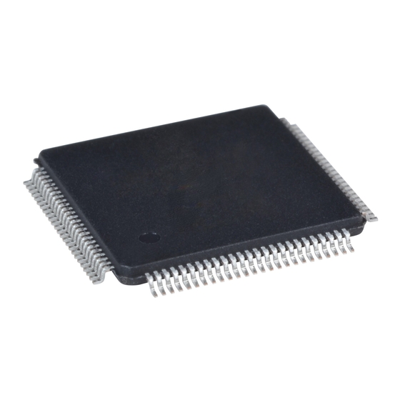
Embedded RAMDAC LCD/CRT Controller
Brand:
Epson
| Category:
Controller
| Size: 9.85 MB
Table of Contents
Section 1
6
Table of Contents
6
Overview Description
13
Introduction
13
Scope
13
Display Support
14
Features
14
CPU Interface
14
Memory Interface
14
Display Modes
15
Display Features
15
Clock Source
15
Miscellaneous
15
Figure 3-1 Typical System Diagram (SH-4 Bus, 256Kx16 FPM/EDO-DRAM)
16
Figure 3-2 Typical System Diagram (SH-3 Bus, 256Kx16 FPM/EDO-DRAM)
16
Figure 3-4 Typical System Diagram (MC68K Bus 2, 32-Bit 68030, 256Kx16 FPM/EDO-DRAM)
17
Figure 3-3 Typical System Diagram (MC68K Bus 1, 16-Bit 68000, 256Kx16 FPM/EDO-DRAM)
17
Figure 3-5 Typical System Diagram (Generic Bus, 1Mx16 FPM/EDO-DRAM)
18
Figure 3-6 Typical System Diagram
18
Figure 3-7 Typical System Diagram (Philips PR31500/PR31700 Bus, 1Mx16 FPM/EDO-DRAM)
19
Figure 3-8 Typical System Diagram (Toshiba TX3912 Bus, 1Mx16 FPM/EDO-DRAM)
19
Figure 3-9 Typical System Diagram (Power PC Bus, 256Kx16 FPM/EDO-DRAM)
20
Figure 3-10 Typical System Diagram (PC Card (PCMCIA) Bus, 1Mx16 FPM/EDO-DRAM)
20
Host Interface
21
Figure 4-1 System Block Diagram Showing Datapaths
21
Cpu R/W
21
Display FIFO
21
Register
21
Internal Description
21
Block Descriptions
21
Memory Controller
21
Block Diagram Showing Datapaths
21
Look-Up Tables
22
Crtc
22
LCD Interface
22
Dac
22
Power Save
22
Clocks
22
Cursor FIFO
22
Figure 5-1 Pinout Diagram
23
Pinout Diagram
23
Pins
23
Pin Description
24
Host Interface
25
Table 5-1 Host Interface Pin Descriptions
25
Memory Interface
29
Table 5-2 Memory Interface Pin Descriptions
29
LCD Interface
30
CRT Interface
30
Table 5-3 LCD Interface Pin Descriptions
30
Table 5-4 Clock Input Pin Description
30
Miscellaneous
31
Table 5-5 Miscellaneous Interface Pin Descriptions
31
Table 5-7 CPU Interface Pin Mapping
32
Table 5-6 Summary of Power on / Reset Options
32
Multiple Function Pin Mapping
32
Summary of Configuration Options
32
Table 5-8 Memory Interface Pin Mapping
33
Table 5-9 LCD Interface Pin Mapping
34
CRT Interface
35
Figure 5-2 External Circuitry for CRT Interface
35
C. Characteristics
36
Table 6-1 Absolute Maximum Ratings
36
Table 6-2 Recommended Operating Conditions
36
Table 6-4 Electrical Characteristics for V
36
Table 6-3 Electrical Characteristics for
37
Table 6-5 Electrical Characteristics for VDD = 3.0V Typical
37
Figure 7-1 SH-4 Timing
38
CPU Interface Timing
38
Interface Timing
38
C. Characteristics
38
Table 7-1 SH-4 Timing
39
Figure 7-2 SH-3 Timing
40
Table 7-2 SH-3 Timing
41
MC68K Bus 1 Interface Timing (E.g. MC68000)
42
Figure 7-3 MC68000 Timing
42
Table 7-3 MC68000 Timing
43
MC68K Bus 2 Interface Timing (E.g. MC68030)
44
Figure 7-4 MC68030 Timing
44
Table 7-4 MC68030 Timing
45
PC Card Interface Timing
46
Figure 7-5 PC Card Interface Timing
46
Table 7-5 PC Card Interface Timing
47
Generic Interface Timing
48
Figure 7-6 Generic Timing
48
Table 7-6 Generic Timing
49
MIPS/ISA Interface Timing
50
Figure 7-7 MIPS/ISA Timing
50
Table 7-7 MIPS/ISA Timing
51
Philips Interface Timing (E.g. PR31500/PR31700)
52
Figure 7-8 Philips Timing
52
Figure 7-9 Clock Input Requirements for BUSCLK Using Philips Local Bus
53
Table 7-8 Philips Timing
53
Table 7-9 Clock Input Requirements for BUSCLK Using Philips Local Bus
53
Toshiba Interface Timing (E.g. TX3912)
54
Figure 7-10 Toshiba Timing
54
Table 7-10 Toshiba Timing
55
Figure 7-11 Clock Input Requirements
56
Table 7-11 Clock Input Requirements for BUSCLK Using Toshiba Local Bus
56
Powerpc Interface Timing (E.g. Mpc8Xx, MC68040, Coldfire)
57
Figure 7-12 Powerpc Timing
57
Table 7-12 Powerpc Timing
57
Clock Input Requirements
58
Figure 7-13 Clock Input Requirements
58
Table 7-13 Clock Input Requirements for CLKI Divided down Internally (MCLK = CLKI/2)
58
Table 7-14 Clock Input Requirements for CLKI
58
Figure 7-14 EDO-DRAM Read/Write Timing
59
Figure 7-15 EDO-DRAM Read-Write Timing
59
Table 7-15 EDO DRAM Read Timing
60
Table 7-16 EDO DRAM CAS before RAS Refresh Write Timing
61
EDO-DRAM CAS before RAS Refresh Timing
61
Figure 7-16 EDO-DRAM CAS before RAS Refresh Write Timing
61
Table 7-17 EDO-DRAM Self-Refresh Timing
62
EDO-DRAM Self-Refresh Timing
62
Figure 7-17 EDO-DRAM Self-Refresh Timing
62
FPM-DRAM Read / Write / Read - Write Timing
63
Figure 7-18 FPM-DRAM Read/Write Timing
63
Figure 7-19 FPM-DRAM Read-Write Timing
63
Table 7-18 FPM-DRAM Read/Write/Read-Write Timing
64
FPM-DRAM CAS before RAS Refresh Timing
65
Figure 7-20 FPM-DRAM CAS before RAS Refresh Timing
65
Table 7-19 FPM-DRAM CAS before RAS Refresh Timing
65
FPM-DRAM Self-Refresh Timing
66
Figure 7-21 FPM-DRAM Self-Refresh Timing
66
Table 7-20 FPM DRAM Self-Refresh Timing
66
Table 7-21 LCD Panel Power Off/ Power on
67
LCD Power Sequencing
67
Power Sequencing
67
Power Save Status
68
Figure 7-23 Power Save Status and Local Bus Memory Access Relative to Power Save Mode
68
Table 7-22 Power Save Status and Local Bus Memory Access Relative to Power Save Mode
68
Display Interface
69
4-Bit Single Monochrome Passive LCD Panel Timing
69
Figure 7-24 4-Bit Single Monochrome Passive LCD Panel Timing
69
Figure 7-25 4-Bit Single Monochrome Passive LCD Panel A.C. Timing
70
Table 7-23 4-Bit Single Monochrome Passive LCD Panel A.C. Timing
70
8-Bit Single Monochrome Passive LCD Panel Timing
71
Figure 7-26 8-Bit Single Monochrome Passive LCD Panel Timing
71
Table 7-24 8-Bit Single Monochrome Passive LCD Panel A.C. Timing
72
Figure 7-27 8-Bit Single Monochrome Passive LCD Panel A.C. Timing
72
4-Bit Single Color Passive LCD Panel Timing
73
Figure 7-28 4-Bit Single Color Passive LCD Panel Timing
73
Figure 7-29 4-Bit Single Color Passive LCD Panel A.C.timing
74
Table 7-25 4-Bit Single Color Passive LCD Panel A.C.timing
74
8-Bit Single Color Passive LCD Panel Timing (Format 1)
75
Figure 7-30 8-Bit Single Color Passive LCD Panel Timing (Format 1)
75
Figure 7-31 8-Bit Single Color Passive LCD Panel A.C. Timing (Format 1)
76
Table 7-26 8-Bit Single Color Passive LCD Panel A.C. Timing (Format 1)
76
8-Bit Single Color Passive LCD Panel Timing (Format 2)
77
Figure 7-32 8-Bit Single Color Passive LCD Panel Timing (Format 2)
77
Figure 7-33 8-Bit Single Color Passive LCD Panel A.C. Timing (Format 2)
78
Figure 7-34 16-Bit Single Color Passive LCD Panel Timing
79
16-Bit Single Color Passive LCD Panel Timing
79
Figure 7-35 16-Bit Single Color Passive LCD Panel A.C. Timing
80
8-Bit Dual Monochrome Passive LCD Panel Timing
81
Table 7-29 8-Bit Dual Monochrome Passive LCD Panel A.C. Timing
82
8-Bit Dual Color Passive LCD Panel Timing
83
Table 7-30 8-Bit Dual Color Passive LCD Panel A.C. Timing
84
16-Bit Dual Color Passive LCD Panel Timing
85
Table 7-31 16-Bit Dual Color Passive LCD Panel A.C. Timing
86
16-Bit TFT/D-TFD Panel Timing
87
Table 7-32 16-Bit TFT/D-TFD A.C. Timing
88
CRT Timing
89
Table 7-33 CRT A.C. Timing
90
Table 8-1 S1D13505 Addressing
91
Registers
91
Register Mapping
91
Register Descriptions
92
Revision Code Register
92
Memory Configuration Registers
92
Table 8-2 DRAM Refresh Rate Selection
92
Panel/Monitor Configuration Registers
93
Table 8-3 Panel Data Width Selection
93
Table 8-4 FPLINE Polarity Selection
95
Table 8-5 FPFRAME Polarity Selection
97
Display Configuration Registers
98
Table 8-6 Simultaneous Display Option Selection
98
Clock Configuration Register
102
Power Save Configuration Registers
103
Miscellaneous Registers
104
Look-Up Table Registers
109
Ink/Cursor Registers
110
Display Buffer
113
Image Buffer
114
Ink/Cursor Buffers
114
Half Frame Buffer
114
Display Configuration
115
Display Mode Data Format
115
Image Manipulation
117
Look -U P Table Architecture
118
Monochrome Modes
118
Bit-Per-Pixel Monochrome Mode
118
Color Display Modes
120
Bit-Per-Pixel Color Mode
121
Bit-Per-Pixel Color Mode
122
Ink /Cursor Architecture
125
Ink/Cursor Buffers
125
Ink/Cursor Data Format
125
Ink/Cursor Image Manipulation
126
Ink Image
126
Cursor Image
126
Swivel View Tm
127
Concept
127
Image Manipulation in Swivelview TM
128
Physical Memory Requirement
129
Limitations
130
Clocking
131
Maximum MCLK: PCLK Ratios
131
Frame Rate Calculation
132
Bandwidth Calculation
134
Power Save Modes
137
Mechanical Data
138
Section 2
140
Introduction
143
Initialization
144
Miscellaneous
146
Display Buffer Location
147
Memory Organization for One Bit-Per-Pixel (2 Colors/Gray Shades)
147
Memory Organization for Two Bit-Per-Pixel (4 Colors/Gray Shades)
147
Memory Organization for Eight Bit-Per-Pixel (256 Colors/16 Gray Shades)
148
Memory Organization for Four Bit-Per-Pixel (16 Colors/Gray Shades)
148
Memory Organization for Fifteen Bit-Per-Pixel (32768 Colors/16 Gray Shades)
149
Memory Organization for Sixteen Bit-Per-Pixel (65536 Colors/16 Gray Shades)
149
Look -U P Table (Lut)
150
Look-Up Table Registers
150
Look-Up Table Organization
151
Advanced Techniques
157
Virtual Display
157
Examples
158
Registers
158
Panning and Scrolling
159
Registers
160
Examples
161
Registers
162
Split Screen
162
Examples
163
Introduction to LCD Power Sequencing
164
Lcd Power Sequencing and Power Save Modes
164
Registers
164
LCD Enable/Disable
165
Hardware Cursor
166
Introduction
166
Registers
166
Examples
168
Limitations
168
No Top/Left Clipping on Hardware Cursor
168
Reg[29H] and Reg[2Bh]
168
Reg[30H]
168
Hardware Rotation
169
Introduction to Hardware Rotation
169
S1D13505 Hardware Rotation
169
Registers
170
Examples
171
Limitations
171
Crt Considerations
173
CRT Only
173
Introduction
173
Simultaneous Display
173
Identifying the S1D13505
174
API for 13505HAL
175
Hardware Abstraction Layer (Hal)
175
Initialization
175
Introduction
175
General HAL Support
178
Advanced HAL Functions
181
Register / Memory Access
183
Color Manipulation
185
Drawing
187
Hardware Cursor
189
Ink Layer
192
Power Save
195
X-LIB Support
196
Introduction
197
Sample Code
197
Sample Code Using the 13505HAL API
197
Sample Code Without Using the 13505HAL API
199
Header Files
205
Appendix Supported Panel Values
212
Section 3
216
13505Cfg Configuration Program
219
Installation
219
S1D13505 Supported Evaluation Platforms
219
Usage
219
13505CFG Configuration
220
General Page
221
Memory Page
222
Panel Page
223
CRT Page
224
Default Page
225
Open Dialog Box
226
Save as Dialog Box
227
Example
228
Comments
229
Sample Program Messages
230
13505Show
231
13505Show Demonstration Program
231
Installation
231
S1D13505 Supported Evaluation Platforms
231
13505SHOW Examples
232
Usage
232
Comments
233
Program Messages
234
13505Splt
235
13505Splt Display Utility
235
Installation
235
S1D13505 Supported Evaluation Platforms
235
13505SPLT Example
236
Comments
236
Usage
236
Program Messages
237
13505Virt
238
13505Virt Display Utility
238
Installation
238
S1D13505 Supported Evaluation Platforms
238
13505VIRT Example
239
Comments
239
Usage
239
Program Messages
240
13505Play
241
13505Play Diagnostic Utility
241
Installation
241
S1D13505 Supported Evaluation Platforms
241
Usage
242
13505PLAY Example
243
Comments
244
Scripting
244
Program Messages
245
13505Bmp
246
13505Bmp Demonstration Program
246
13505BMP Examples
246
Installation
246
S1D13505 Supported Evaluation Platforms
246
Usage
246
UTILITIES (X23A-B-001-02) EPSON 3-I
246
Comments
247
Program Messages
247
13505Pwr Software Suspend Power Sequencing Utility
248
Installation
248
S1D13505 Supported Evaluation Platforms
248
Section 4
252
Features
254
Introduction
254
Cpu/Bus Interface Connector Pinouts
257
Host Bus Interface Pin Mapping
259
Clock Input Support
260
Decode Logic
260
DRAM Support
260
ISA Bus Support
260
Non-ISA Bus Support
260
Technical Description
260
Adjustable LCD Panel Negative Power Supply
261
Adjustable LCD Panel Positive Power Supply
261
Color Passive LCD Panel Support
261
Color TFT/D-TFD LCD Panel Support
261
CRT Support
261
Monochrome LCD Panel Support
261
Power Save Modes
261
Cpu/Bus Interface Header Strips
262
Schematic Notes
262
Parts List
263
Schematic Diagrams
264
Section 5
269
General Description
272
Interfacing the S1D13505 to the Pc Card Bus
272
Introduction
272
Register/Memory Mapping
273
Hardware Configuration
274
Performance
274
S1D13505 Configuration
274
Interfacing to the Nec V R 4102 Tm /V R 4111 Tm Microprocessor
275
Hardware Description
276
NEC V R 4102 TM /V R 4111 TM Configuration
276
S1D13505 Configuration
276
Interfacing to the Nec
277
Introduction
277
Nec V Rtm
280
S1D13505 Configuration
280
S1D13505 Pin Mapping
280
Interfacing to the Philips Mips Pr31500/Pr31700 Processor
281
Interfacing to the PR31500/PR31700
281
Introduction
281
PR31500/PR31700 Host Bus Interface Pin Mapping
282
PR31500/PR31700 Host Bus Interface Signals
282
S1D13505 Host Bus Interface
282
Direct Connection to the Philips PR31500/PR31700
283
Hardware Description
283
Memory Mapping and Aliasing
285
S1D13505 Configuration
285
Hardware Description
286
IT8368E Configuration
286
S1D13505 Configuration
286
System Design Using the IT8368E PC Card Buffer
286
Software
287
Interfacing to the Toshiba Mips Tx3912 Processor
288
Interfacing to the TX3912
288
Introduction
288
S1D13505 Host Bus Interface
289
TX3912 Host Bus Interface Pin Mapping
289
Direct Connection to the Toshiba TX3912
290
Hardware Description
290
TX3912 Host Bus Interface Signals
290
Memory Mapping and Aliasing
292
S1D13505 Configuration
292
Hardware Description
293
IT8368E Configuration
293
S1D13505 Configuration
293
System Design Using the IT8368E PC Card Buffer
293
Software
294
General Description
295
Introduction
295
Mmpc821 M
295
Hardware Connections
296
Hardware Configuration
298
S1D13505 Configuration
298
MPC821 Chip Select Configuration
299
Test Software
300
Test Software Source Code
300
Dac Application Notes
301
Introduction
301
Notes When Operating the S1D13505 Built-In DAC
301
DAC Isolated Power Source
302
Peripheral Circuit of DAC Pins
303
RED/GREEN/BLUE Pins
304
HRTC and VRTC Pins
305
IREF Pin
305
Isolated DAC Power Pin
306
Notes When the DAC Is Not Used
306
Isolated DAC Signal Pins
307
Power Consumption
308
S1D13505 Power Consumption
308
Conditions
309
Build for the Hitachi D9000 and ETMA ODO Evaluation Systems
312
Example Driver Builds
312
Program Requirements
312
Windows ® Ce Display Drivers
312
Build for CEPC (X86)
314
Example Installation
316
Installation for CEPC Environment
316
Installation for Hitachi D9000 and ETMA ODO
316
Advertisement
Advertisement
Related Products
Epson S1D13504
Epson S1D13506
Epson S1D13503 Series
Epson S1D13503D00A
Epson S1D13503F00A
Epson S1D13503F01A
Epson S1D13503P00C
Epson S1D13706
Epson S1D13700
Epson S1D13704
Epson Categories
Printer
Projector
All in One Printer
Scanner
Printer Accessories
More Epson Manuals
Login
Sign In
OR
Sign in with Facebook
Sign in with Google
Upload manual
Upload from disk
Upload from URL