
Related Manuals for Epson S1C17M03


Summary of Contents for Epson S1C17M03
- Page 1 S1C17M03 Software Setup Guide © Seiko Epson Corporation. 2022. All right reserved.
- Page 2 Contents ◆ Introduction ◆ Working Environment ◆ About GNU 17V3 ◆ About ICDmini V3 ◆ About user sites ◆ Program development ◆ Evaluation board connection ◆ From program writing to debugging ◆ Reference...
- Page 3 Introduction This setup guide explains how to install the C compiler package, which is GNU17V3, import sample projects, build the projects, connect an emulator and an evaluation board, and execute the program.
-
Page 4: Working Environment
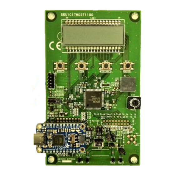
Working Environment PC(OS:Windows10): ⁃ S1C17 Software Integrated Development Environment (GNU17V3) ⁃ Latest model-specific information file ⁃ Sample software and PC software emulator: ⁃ S5U1C17001H3(ICDminiV3) ⁃ USB cable ⁃ 10-pin connector Evaluation board for S1C17Family: ⁃ S5U1C17M03T... - Page 5 About GNU 17V3 GNU17V3 is a software integrated development environment for developing software on a PC. GNU17V3 includes a set of software tools and utilities that compile C source programs, assemble assembly source programs, debug them, and create executable and motorola files. ◆...
- Page 6 About ICDmini V3 S5U1C17001H (ICDmini) connects the S1C17 microcomputer on the target system and GNU17V3, and provides an environment for debugging on the target system together with GNU17V3.
- Page 7 About user sites We publish information related to the target MCU on the user site. Please download the latest GNU 17V3 and model-specific information files required for software development from the following. 16bit Microcontroller -Software Tool- Products - Semicon Top – Epson...
-
Page 8: Program Development
Program development... - Page 9 Booting GNU 17V3 1. To start GNU17, please start from Windows Startup Menu, and continue in order of [EPSON MCU] > [GNU17V3 IDE]. 2. Please select a Workspace. 3. After a while, GNU17 is started. Please click on [Workbench] to close the Welcome window (the welcome...
- Page 10 Importing sample projects(1) 1. Please click on [File] at the upper left corner, and select [Import]. 1. Please select [Existing Projects into Workspace] under [General], and click [Next>].
- Page 11 Importing sample projects(2) 3. To select root directory, please click on [Browse…], and select a sample project for GNU17V3. 4. Please check the [Copy projects into workspace] check box, and click on [Finish]. This is the end of importing sample projects.
- Page 12 Download model information file 1. Please download the latest model-specific information file from the following URL. https://global.epson.com/products_and_drivers/semicon/pr oducts/micro_controller/16bit/sw_tool.html 2. Please replace with the following folder. C:¥EPSON¥GNU17V3¥mcu_model...
-
Page 13: Project Settings
Project settings 1. Please check if there is the sample project file on a Project Explorer window, and open it with a Double-Click. 2. Please open in the order of [Project] > [Properties] > [GNU17 Setting], and check if Target CPU is selected correctly. (Target CPU is related to the evaluation board.) - Page 14 Startup processing library (crt0.o) GNU17V3 automatically incorporates the startup processing library “crt0.o” including the vector table, start and end functions when creating a project. Therefore, the program starts from crt0.o. The source code for crt0.o can be found below. C¥EPSON¥GNU17V3¥utility¥lib_src¥crt0.c...
-
Page 15: Building Projects
Building Projects(1) 1. Please click on [Build Project] under [Project]. 2. Building project is being started. - Page 16 Building Projects(2) 3. Please open the [Console] tab which is located on under the middle window, and see [Build Finished] message. In addition, please open [Problems] tab and check if there is no error.
- Page 17 Evaluation board connection...
-
Page 18: Usb Driver Installation
USB driver installation(1) 1. Moving on to install an USB driver for ICDminiV3 on the PC. Please connect only ICDminiV3 with PC, and check if green LED turns on. (It turns on after it blinks a couple of times.) 2. Please open [Control Panel] under Windows Menu, and click on [Hardware and Sound]. - Page 19 USB driver installation(2) 3. Please Right-Click on [Unknown devices], and renew the driver. “How do you want to search for drivers?” choose [Browse my computer for driver software] 4. Please Right-Click on [Unknown devices], and renew the driver. “How do you want to search for drivers?”...
- Page 20 ICDminiV3 connection Connect the ICDminiV3 to the evaluation board. 1PIN = red cable JP3 should short-circuit VDD_ICD. 2. Please connect the emulator and the evaluation board with the PC. Check if both green and red LEDs are on. If those do not turn on, please check the connection.
- Page 21 From program writing to debugging...
- Page 22 Launch the debugger(1) Please select [Run] > [Debug Configurations] 2. Under [C/C++ Application], please choose the sample project that is supposed to execute. Please click on [Debugger] tab, and edit the [GDB command file]. 3. If ICDmini Ver.3 is used, enter [gdbmini3.ini].Please click on [Debug] then.
- Page 23 Launch the debugger(2) 3. Debugging is started, and progress bar is shown at the right bottom corner. (Enlarged picture) 4. After a short time, [Confirm Perspective Switch] window appears. Please click on [Yes].
- Page 24 Launch the debugger(3) 5. Window is shifted Debug window. Please click on [Display Selected Console ]pulldown, and select an option that end with […¥gdb]. Please check if any errors do not appear.
- Page 25 How to read error messages When starting the debugger, the following message will be displayed if a problem occurs. (The text of this message has no meaning.) If this message is displayed, follow "Start Debugger (3)", click the [Display Selected Console] pull-down menu at the bottom right, and then click the option ending with […...
- Page 26 Time to write When the debugger is started, the program is written to the built-in Flash of the target IC. The time required for writing varies depending on the program size, but a guideline is given in the following file. C:¥EPSON¥GNU17V3¥mcu_model¥17M03¥fls¥fls17m03_readme_e.txt...
-
Page 27: Executing The Program
Executing the Program(1) 1. Please click on [Resume 2. Sample project is executed. - Page 28 Executing the Program(2) 3. Please click on [ ] to suspend the program, and click on [ ] to terminate the program. Please click on [ ] to reset the program, and click on [ ] to reset the program and the target.
- Page 29 I explained the basic operation of the software development environment. In the software development environment we provide, various other functions are available. If you have any problems, we recommend that you refer to the following tutorials and manuals. ◼ GNU17V3 Manual https://global.epson.com/products_and_drivers/semicon/pdf/id003054.pdf ◼ ICDminiV3 Manual https://global.epson.com/products_and_drivers/semicon/pdf/id002781.pdf...
- Page 30 2.This evaluation board/kit or development tool is intended for use by an electronic engineer and is not a consumer product. The user should use it properly and in a safe manner. Seiko Epson does not assume any responsibility or liability of any kind of damage and/or fire caused by its use.
Need help?
Do you have a question about the S1C17M03 and is the answer not in the manual?
Questions and answers