Table of Contents
Advertisement
Advertisement
Table of Contents

Related Manuals for Bunn Fast Cup Series


Summary of Contents for Bunn Fast Cup Series
- Page 1 Fast Cup ® Bean-to-Cup Single Serve Brewer SERVICE & REPAIR MANUAL Bunn-O-Matic Corporation Post Office Box 3227, Springfield, Illinois 62708-3227 Phone (217) 529-6601 | Fax (217) 529-6644 Technical Support Phone (800) 420-2866 www.bunn.com 57471.0000 B 11/22 © 2019 Bunn-O-Matic Corporation...
- Page 2 SOLE OPTION AS SPECIFIED HEREIN, TO REPAIR, REPLACEMENT OR REFUND. In no event shall BUNN be liable for any other damage or loss, including, but not limited to, lost profits, lost sales, loss of use of equipment, claims of Buyer's customers, cost of capital, cost of down time, cost of substitute equipment, facilities or services, or any other special, incidental or consequential damages.
-
Page 3: Table Of Contents
INDEX Troubleshooting Guide ......................5 User Icons & Technician Icon Overview ................16 Technician Service Access Instruction ................18 Technician Service Tabs/Folders Overview ............... 19 Exterior .......................... 20 • Coffee Bean Hoppers • Drip Tray • Grounds Bin Lower Door Cover ......................26 •... - Page 4 INDEX Right Panel ........................76 • Main On/Off Switch • Fuse Holder & Fuse • Lower & Upper Door Interrupt Switch • Circuit Breaker • Input/Output Board • Power Board (High Voltage) • Universal Power Supply - 24.0VDC Output • Universal Power Supply - 48.0VDC Output Rear Panel ........................
-
Page 5: Troubleshooting Guide
Probable Causes and Tests/Remedies for problems encountered. In the event of a machine problem, power cycle the machine and see if the machine resets back into operation. If a problem persists and after exhausting the probable causes and remedies, contact the Bunn-O-Matic Technical Support Department. •... - Page 6 TROUBLESHOOTING MACHINE MESSAGES, SYMP- PROBABLE CAUSE REMEDY TOMS and/or ACTIVE NOTICES Messages 3. Drip Tray Removed - Please a. Drip tray is removed a. Install drip tray & install/removed op- Replace the Drip Tray eration can be viewed under the Service icon/Sensor tab b.
- Page 7 TROUBLESHOOTING MACHINE MESSAGES, SYMP- PROBABLE CAUSE REMEDY TOMS and/or ACTIVE NOTICES Messages 7. Door Open - Please Close to Continue a. Machine lower or upper door is open a. Close the open door. The switch opera- Operation tion “closed/open” can be viewed under b.
- Page 8 TROUBLESHOOTING MACHINE MESSAGES, SYMP- PROBABLE CAUSE REMEDY TOMS and/or ACTIVE NOTICES Symptoms 10. Coffee Profile is Weak a. Coffee beans low or bridging in hopper a. Refill hopper or remove and empty hopper, clean, dry and refill hopper b. Coffee particle size may need to be b.
- Page 9 TROUBLESHOOTING MACHINE MESSAGES, SYMP- PROBABLE CAUSE REMEDY TOMS and/or ACTIVE NOTICES Symptoms Entire Home Screen “Grayed Out” c. Tank Temperature Too Low c. Brew Lockout feature enabled. Found under Machine Settings icon/Tempera- ture tab d. Open or Failed Door Interrupt Switch d.
- Page 10 TROUBLESHOOTING MACHINE MESSAGES, SYMP- PROBABLE CAUSE REMEDY TOMS and/or ACTIVE NOTICES Symptoms 15. Water Dripping On Counter a. Hydraulic Module: Improper tube a. Locate leak, release tube from push- installation, length or cutting of tube in fitting and inspect tube length and end for straight cut.
- Page 11 TROUBLESHOOTING MACHINE MESSAGES, SYMP- PROBABLE CAUSE REMEDY TOMS and/or ACTIVE NOTICES Hydraulic Module Active Notices 17. Fill Time Too Long or Low Water a. Main water supply a. Ensure main water supply is turned On Supply b. Restricted Water Filtration System - b.
- Page 12 TROUBLESHOOTING MACHINE MESSAGES, SYMP- PROBABLE CAUSE REMEDY TOMS and/or ACTIVE NOTICES Hydraulic Module Active Notices 19. Brew Error Pump Timeout, Push-out a. Main water supply or water filtration a. Ensure adequate incoming water Timeout or Flow Limit system pressure b. Restricted brew chamber filter screens b.
- Page 13 TROUBLESHOOTING MACHINE MESSAGES, SYMP- PROBABLE CAUSE REMEDY TOMS and/or ACTIVE NOTICES Brew Module Active Notices 22. No Latch - the recipe does not allow a. Grinder adjustment change and/or a. Verify the grind coarseness and re- the entry of more than 45 grams calibration is not correct calibrate grinder 23.
- Page 14 TROUBLESHOOTING MACHINE MESSAGES, SYMP- PROBABLE CAUSE REMEDY TOMS and/or ACTIVE NOTICES Brew Module Active Notices Piston Not Home,Timeout, Stall , No c. Piston Motor c. Ensure both door switches are in Latch or Communication Error service mode. Test piston motor for 48.0 VDC d.
- Page 15 TROUBLESHOOTING MACHINE MESSAGES, SYMP- PROBABLE CAUSE REMEDY TOMS and/or ACTIVE NOTICES Miscellaneous Active Notices 28. No or Loss of Communication a. Wiring harness a. Check wiring harness for loose con- nection between Touchscreen and Input/ Output circuit board J15 connector 29.
-
Page 16: User Icons & Technician Icon Overview
Portion Size selection and Start button. 2. BUNN Logo icon; Button used to enter Service Access Level by touching the logo button for 5 seconds. Service Access Level icons; Care and Cleaning, Active Notice and Advanced Icons. - Page 17 SERVICE 5. Advanced icon; Used to access Advanced Level icons. A User or Technician password is re- quired to enter icons. a) Recipes icon; How the beverage is made. - Adjustment settings for volume - Pre-infusion - By-pass - Grind weight for each portion size - Immersion time - Brew rate/seconds NOTE: The Test Recipe function is...
-
Page 18: Technician Service Access Instruction
SERVICE TECHNICIAN SERVICE ACCESS Instruction 1. Touch and hold the BUNN logo for a few seconds until SERVICE ACCESS appears on the display. Select the ADVANCED icon. 3. Two Advanced icon screens available. a) USER passcode 6601. b) Technician passcode xxxx. Contact the Bunn-O- Matic Customer Service Department. -
Page 19: Technician Service Tabs/Folders Overview
SERVICE TECHNICIAN SERVICE TABS/FOLDERS OVER- Example VIEW Tabs/Folders Service Tab/Folder Purpose Test piston motor, swiper removal and piston home Brew Module status and location stop- ping points Test all water valves, water pump, flow meter counts. Water System Also, monitor water and brew pressure Monitor all 3 tank tem- peratures, test solid state... -
Page 20: Exterior
SERVICE EXTERIOR REMOVABLE ATTACHMENT ASSEMBLIES Location: The brewer has removable attachment assemblies. Once you have removed a coffee bean hopper, grounds bin or drip tray, the machine will not be able to be operate. The machine can remain connected to the power sup- ply in order to troubleshoot the removable attachment and sensors by entering Service Technician mode. - Page 21 SERVICE EXTERIOR Coffee Bean Hopper Assembly Purpose: Holds approximately 3.5lbs coffee beans. The hopper retains a magnet for hopper detection circuit. The slide gate is used to shut off coffee beans for hopper removal and used as a hopper lock when in position. It only takes 1 hopper to be removed or not detected out of the three which will result in the brewer being disabled or cannot brew.
-
Page 22: Drip Tray
SERVICE EXTERIOR DRIP TRAY ASSEMBLY Purpose: The drip tray is the collection area for sanitize, rinse and expansion water. The water is directed out a drain fitting, through a drain tube and exits into the site drain. A drip tray detection circuit is incorporated within the brewer to ensure drip tray is in position for brewer operation. -
Page 23: Grounds Bin
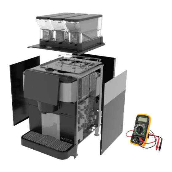
SERVICE EXTERIOR GROUNDS BIN ASSEMBLY Purpose: The grounds bin is the storage area for semi wet coffee grinds after brewing. The brewer does have a grounds bin detection circuit and a Full and Almost Full Warning message based off the amount of spent grounds from each beverage selec- tion. - Page 24 SERVICE ACCESSING INSIDE OF THE BREWER Location: The brewer has removable panels to access inside the brewer to perform any necessary repair. In order to work safely, the power should be disconnected prior to removal of any body panel. Once you have access to the internal components, the power may be reconnected in order to troubleshoot the brewer.
- Page 25 SERVICE LOWER & UPPER DOOR OVERVIEW Front Lower & Upper Door Open Position Step 1: Open lower door. Step 2: Lift upper door assembly until upper assembly locks in position. NOTE: Key may be needed to unlock upper door assembly. Accesses Coffee waste bin, drip tray or chute, main on/off switch, door interrupt switches.
-
Page 26: Lower Door Cover
SERVICE LOWER DOOR COVER & DOOR REMOVAL INSTRUCTIONS Lower Door Parts A. Door Cover B. Door Back Plate C. Door Hinges D. ADA Switch membrane Door Cover Removal Steps Step 1: Open lower door. Step 2: Remove Qty-4 philip head style screws from the center of the door rear panel. - Page 27 SERVICE LOWER DOOR COVER Female Molex Door Cable Connector ADA Membrane Switch Terminal 1 Brown Wire Purpose: People with disabilities may use the mem- Terminal 2 Red Wire....a brane switch to operate the brewer touchscreen to Terminal 3 Orange Wire .....b select, start and/or stop the brew dispense process.
-
Page 28: Upper Door Cover
SERVICE UPPER DOOR COVER WITH TOUCHSCREEN REMOVAL INSTRUCTION Upper Door Cover Removal Instructions Step 1: Open lower door. Step 2: Open upper door until right hinge locks upper door in upward position. Step 3: Remove left side panel. Step 4: a) Access dispense nozzle tube under upper door. - Page 29 SERVICE UPPER DOOR COVER WITH TOUCHSCREEN OVERVIEW (continued) Upper Door Cover Removal Instructions Step 9: Raise door cover from metal back plate and disconnect the following harness connectors. a) Qty-2, LED 2 pin connectors. b) Touchscreen cable 12 pin connector. NOTE: Goes through door and back plate where shown.
-
Page 30: Touch Screen Assembly
SERVICE UPPER DOOR COVER Touch Screen Assembly Purpose: The Touch Screen assembly is comprised of a user interface touch screen display and circuit board. The user interface touch screen continuously monitors the events of inputs from devices which results in operation of the I/O board and/or Power board to activate the load components. - Page 31 SERVICE UPPER DOOR COVER Volt/Ohm Meter - Voltage Check Step 6: Disconnect or unplug machine from power. Step 7: Remove right panel to access circuit boards. Step 8: Locate J17 connector on the Input/Output board. Note: Touch Screen receives power from J17 connector.
- Page 32 SERVICE UPPER DOOR COVER Dispense Block Assembly Purpose: The dispense block has two recessed blue LED’s within the block. A laminar nozzle aerates the product flow thus creating a non-splashing stream entering the coffee cup. TEST INSTRUCTION Volt/Ohm Meter - Voltage Check Ensure brewer is powered and upper and lower door are closed.
-
Page 33: Door Fan
SERVICE UPPER DOOR COVER Upper Door Fan Purpose: Fan is rated 24VDC and operates 24/7. The fan circulates air inside the upper door and exits out the door back plate. TEST INSTRUCTION Volt/Ohm Meter - Voltage Check Door Fan When the brewer is powered up, the fan should be operating regardless if either door interrupt switch is open. -
Page 34: Wifi Board
I/O board and Wifi board. Voltage Output Not Present at I/O board: Replace I/O board. PART RELATES TO THE FOLLOWING SYMPTOM • Active Notice - E-019: Loss of BUNN Link Error OPTIONAL OPTIONAL... -
Page 35: Top Panel
SERVICE TOP PANEL REMOVAL INSTRUCTIONS Top Panel Parts A. Qty-3 Coffee Bean Hopper Assembly. *Lid *Finger Guard *Magnet *Hopper Gate/Lock B. Top Panel. C. Grommet - Tablet Inlet. D. Qty-3 Hopper Detect Reed Switch. E. Qty-3 Coffee Bean Detect Full/Empty Sensor. Steps 1. - Page 36 SERVICE TOP PANEL Coffee Bean Hopper Detect Switch Purpose: A normally open switch that will close when a magnetic field is applied. The magnet located in the bottom of each hopper will close the switch when the hopper is in position directly over the reed switch.
- Page 37 Right Hopper - J6-5 YEL & J6-6 WHT/YEL PART RELATES TO THE FOLLOWING SYMPTOM • Message - Left, Center or Right Hopper Not De- tected - Brewing Disabled 208VAC 2 WIRE + GND SINGLE PHASE 56640.0000A 08/19 ©2019 BUNN-O-MATIC CORPORATION...
- Page 38 SERVICE TOP PANEL Bean Detect Sensor (Full/Empty) LED, Infrared Purpose: Solid state device that consists of an LED Emitter (emitter) & photo transistor (receiver). The solid state device is used to monitor hopper Full/Empty status. If the brewer reads a bean hopper as being empty, it will lock out the user from being able to select and start a brew from that hopper/product selection.
- Page 39 SERVICE TOP PANEL Step 5: Remove right panel to access circuit boards. Step 6: The best place to check for voltage is at J18-9 Pin Connector on the Input/Output board. Step 7: LED - Emitter Information nput/Output Board J18 Connector Left Hopper - J18-1 (+) and J18-3 (-) is 1.20VDC Center Hopper - J18-4 (+) and J18-6 (-) is...
-
Page 40: Lower Front Panel
SERVICE LOWER FRONT PANEL Brew Module Removal Instruction Step 1: Open upper front door. Step 2: Open lower front door. Step 3: Remove Waste Bin. Step 4: Remove drip tray. Step 5: Remove Qty-4, thumb screws securing the inner panel. Remove panel. Step 6: Disconnect upper and lower brew tubes going to the push-in fittings. - Page 41 SERVICE LOWER FRONT PANEL Brew Module Re-Installation Hint: Easier to install module back into the brewer frame when the brew module latch system is engaged. Step 1: Position Brew Module upright with flat bottom on edge of table and module mounting bracket away from table.
- Page 42 SERVICE LOWER FRONT PANEL Step 5: Align studs on top of Brew Module with holes in top of machine interior. Step 6: Swing bottom of Brew Module to align metal plate with thumb screw holes. Step 7: Replace Qty-2 thumb screws. Step 8: Connect the wiring harness at the 12 pin connector junction located on the right inner wall (located by upper...
- Page 43 SERVICE LOWER FRONT PANEL (continued) Brew Module Re-Installation Step 10: With Brew Module secured, return.
- Page 44 SERVICE LOWER FRONT PANEL Brew Chamber with Lower Piston/Screen Filter Screen Purpose: The brew chamber is the area where it Brew receives and holds coffee grounds in preparation of Chamber a pressurized brew process. The maximum limit of coffee grounds that the brew chamber can accept is 45 grams.
- Page 45 SERVICE LOWER FRONT PANEL Upper Piston & Filter Screen Piston Outlet Purpose: The upper piston travels downward from Fitting Home position, enters and seals brew chamber to ready the chamber for pressurized brewing. Brew Upper Piston water enters the bottom of the brew chamber, the extracted coffee will flow through the upper filter screen which will exit out the upper piston fitting, through a dispense valve and exit out the dispense...
- Page 46 SERVICE LOWER FRONT PANEL TEST INSTRUCTION Enter Service Technician Mode and Select Service icon Step 10: Select and enter Brew Module tab. Step 11: Touch Brew Piston Latch button. The upper piston will move to 109mm - Latched position. Step 12: Select and enter Water System tab. Step 13: Place a clean and empty container under the dispense outlet.
-
Page 47: Piston Motor
SERVICE LOWER FRONT PANEL Piston Motor Purpose: A precision motor that moves the upper piston up or down in millimeter increments, staging the upper piston throughout an entire brew or clean process. TEST INSTRUCTION Note: The brewer software controls an incremental process of moving the upper piston within the brew chamber during a brew process and during testing purposes. - Page 48 PART RELATES TO THE FOLLOWING SYMPTOMS • Motor making unusual noise during operation • Active Notice - E-098: Piston Error Comm Fail • Active Notice - E-071: Brew Error Piston Move Timeout 208VAC 2 WIRE + GND SINGLE PHASE 56640.0000A 08/19 ©2019 BUNN-O-MATIC CORPORATION...
-
Page 49: Proximity Sensor
SERVICE LOWER FRONT PANEL Proximity Sensor & Proximity Sensor Locator Post Purpose: The proximity sensor is used to validate “Home” position for the upper piston assembly be- fore start of a brew process. The sensor is mounted to the underside of the piston motor top bracket. - Page 50 Not Home Position - J16-14 Blue wire - J16-5 BLK wire, 4.0VDC. PART RELATES TO THE FOLLOWING SYMPTOMS • Active Notice - E-079: Piston Error Stall Up Not Home Proximity Sensor At Home 208VAC 2 WIRE + GND SINGLE PHASE 56640.0000A 08/19 ©2019 BUNN-O-MATIC CORPORATION Not Home...
- Page 51 SERVICE LOWER FRONT PANEL Swiper Switch Swiper Purpose: A normally open switch that will close Swiper Switch when a magnetic field is applied. The magnet is mounted and sealed in the underside of the swiper assembly. The swiper switch is used to validate swiper position throughout machine operations.
- Page 52 SERVICE LOWER FRONT PANEL Grounds Bin Switch Grounds Bin Switch Purpose: A normally open switch that will close when a magnetic field is applied. The magnet is located in the upper rear of the grounds bin. When the grounds bin is placed in position, the switch will close, enabling the brewer display to allow operation.
- Page 53 SERVICE LOWER FRONT PANEL Volt/Ohm Meter - Continuity Check Step 10: Place grounds bin in corresponding position - Meter should show continuity 0.00 on display or here audible tone. Grounds Bin Removed - Meter should show infinite or open circuit. Step 11: If grounds bin switch shows infinite all the time regardless positioning of magnet near switch - Replace the grounds bin switch.
-
Page 54: Latch Assembly
SERVICE LOWER FRONT PANEL Brew Module Latch Engagement View Latch Assembly Latch Purpose: The upper piston is attached to the latch assembly. Inside the latch assembly is a mechanism that protrudes a latch out each side of the assem- Slot bly. - Page 55 SERVICE SERVICE SERVICE LOWER FRONT PANEL Gas Springs Purpose: The two gas springs assist the rate of fall of Gas Spring the lower brew piston assembly back down to the bot- tom/start position. TEST INSTRUCTION Brew Module Removal Step 1: Release gas spring from lower mount bracket by removing the lower lock pin.
-
Page 56: Left Panel
SERVICE LEFT PANEL Left Side Panel Removal Instructions Step 1: Open lower door. Step 2: Lift upper door assembly until upper assembly locks in position. NOTE: Key may be needed to unlock upper door assembly. Step 3: Remove Qty-1 slotted screw from left side panel in the front. -
Page 57: Water Pressure Regulator
SERVICE LEFT PANEL Water Pressure Regulator Purpose: The pressure regulator is a control valve that reduces the input water pressure to a desired output pressure/flow rate. The brewer internal regulator is factory set at 20psig. Note: Regulator specification is 1 - 25 psig. TEST INSTRUCTION Water Pressure Regulator Factory Setting is 20psig... - Page 58 SERVICE LEFT PANEL Heatsink Block Solid State Relay (SSR) Purpose: The solid state relay with led indicator is made up of solid state components which have no mechanical contacts or moving parts which extends the life of operation. The SSR switches A/C power to the tank heater and provides electrical isolation from the low input D/C control circuit.
- Page 59 SERVICE LEFT PANEL SSR Test Results Step 9: LED not illuminated on SSR, plus zero amp reading - Set voltmeter on D/C voltage and check for 24.0VDC control voltage at SSR being checked. SSR - Finish Step 10: 24.0VDC should be present when SSR Tank/Element test button is touched and go to 0.00VDC when finger is removed from button or 5...
-
Page 60: Flow Meter
SERVICE SERVICE LEFT PANEL LEFT PANEL Flow Meter Purpose: The volumetric meter uses a turbine with magnets. The water passes by the turbine causing the turbine to rotate while the hall affect sensor in- puts the pulse signals for every amount of milliliters passing through. -
Page 61: Brew Pressure Sensor (Transducer)
SERVICE SERVICE LEFT PANEL LEFT PANEL Brew Inline Pressure Sensor (IPS) Purpose: The sensor monitors brew pressure during a brew process. The sensor will input data which may cause a variation in the brew pump motor rpm to maintain a flow rate. TEST INSTRUCTION Enter Service Technician Mode and Select Service icon... - Page 62 SERVICE SERVICE LEFT PANEL LEFT PANEL Volt/Ohm Meter - Voltage Check Step 6: Disconnect or unplug machine from power. Step 7: Remove right panel to access circuit boards. Step 8: Locate J29 connector on the Input/Output board. Step 9: Connect power to machine. Step 10: Set voltmeter on D/C voltage.
- Page 63 SERVICE LEFT PANEL LEFT PANEL Water Inline Pressure Sensor (IPS) Purpose: The water sensor monitors pressure within the water system. Once system pressure reaches 70 or 120psig; the brewer will momentarily activate the purge solenoid valve to relieve and maintain system pressure below 70psig.
- Page 64 Pressure Sensor. WATER OPTIONAL PRESSURE TRANSDUCER PART RELATES TO THE FOLLOWING SYMPTOMS • Active Notice - E-xxx: Currently no error or event code for Water Inline Pressure Sensor 208VAC 2 WIRE + GND SINGLE PHASE 56640.0000A 08/19 ©2019 BUNN-O-MATIC CORPORATION...
-
Page 65: Pressure Control Valve/Safety (12 Bar)
SERVICE LEFT PANEL LEFT PANEL Pressure Control Valve (12 Bar) Purpose: The pressure control valve is used as a back up device if the water system should ever reach 12 Bar (174.05 psig). The mechanical spring/ball valve will open to relieve system pressure to drip tray and close once pressure is reduced below 12 Bar. -
Page 66: Solenoid Valve 3-Way
SERVICE LEFT PANEL LEFT PANEL Chiller Input Coffee Solenoid Valve, 3 Way Purpose: The chiller 3 way “Inlet” solenoid valve is electrically used when a coffee recipe has been originally check marked as an “Ice Beverage” recipe under Recipe set-up mode. The internal paddle seat will move from the normally closed port and seal off the normally open port, directing the coffee through the chiller module and out through another coffee... - Page 67 Beverage is hotter than usual, not cool • Active Notice - E-xxx: Currently no error or event Water System - Chiller Assembly code for Chiller Input Coffee Solenoid Valve Rear View 208VAC 2 WIRE + GND SINGLE PHASE 56640.0000A 08/19 ©2019 BUNN-O-MATIC CORPORATION...
-
Page 68: Solenoid Valve 2-Way
SERVICE LEFT PANEL LEFT PANEL Chiller Output Coffee Solenoid Valve, 3 Way Purpose: The chiller 3 way “Outlet” solenoid valve is electrically used when a coffee recipe has been originally check marked as an “Ice Beverage” recipe under Recipe set-up mode. The internal paddle seat will move from the normally closed port and seal off the normally open drain port, directing the ice coffee beverage out the dispense nozzle. - Page 69 • Active Notice - E-xxx: Currently no error or event Water System - Chiller Assembly Rear View code for Chiller Input Coffee Solenoid Valve 208VAC 2 WIRE + GND SINGLE PHASE 56640.0000A 08/19 ©2019 BUNN-O-MATIC CORPORATION...
- Page 70 SERVICE LEFT PANEL LEFT PANEL Chiller Ambient Drain Solenoid Valve, 2 Way Purpose: The chiller ambient drain valve opens to allow the isolated heat exchanger water from the “ice coffee” brew process to be discharged down the drain. The continual ambient flow into the heat exchanger, discharge through chiller ambient drain valve and into the drip tray, efficiently cools the cof- fee beverage before entering the coffee cup.
- Page 71 Beverage is hotter than usual, not cool • Active Notice - E-xxx: Currently no error or event code for Chiller Input Coffee Solenoid Valve Water System - Chiller Assembly Rear View 208VAC 2 WIRE + GND SINGLE PHASE 56640.0000A 08/19 ©2019 BUNN-O-MATIC CORPORATION...
- Page 72 SERVICE LEFT PANEL Qty-7 - Solenoid Valves, 2 Way Normally Closed Purpose: The coil energizes creating a magnetic field to work against a spring force pivot mounted lever that has a paddle style seal attached to the pivot mount which will move away from outlet seat dur- ing coil activation and will return paddle back to seat position by spring force when coil is de-energized to stop flow through valve.
- Page 73 J20-8 & J20-17 208VAC 2 WIRE + GND SINGLE PHASE Step 9: The reading should be 24.0VDC when 56640.0000A 08/19 ©2019 BUNN-O-MATIC CORPORATION activated in Step 2. Voltage present - Replace Solenoid valve. Voltage not present - Check wiring harness...
- Page 74 SERVICE LEFT PANEL Qty-2 - Solenoid Valves, 2 Way Normally Open Purpose: The coil energizes creating a magnetic field to work against a spring force pivot mounted lever that has a paddle style seal attached to the pivot mount which will move, closing the port during coil activation and will return paddle back to position by spring force when coil is de-energized.
-
Page 75: Solenoid Valve Module
I/O board. Water System Panel Normally Open valves PART RELATES TO THE FOLLOWING SYMPTOMS • Active Notice - E-xxx: Currently no error or event code for Solenoid Valves 208VAC 2 WIRE + GND SINGLE PHASE 56640.0000A 08/19 ©2019 BUNN-O-MATIC CORPORATION... -
Page 76: Right Panel
SERVICE RIGHT PANEL Right Side Panel Removal Instructions Step 1: Open lower door. Step 2: Lift upper door assembly until upper assembly locks in position. NOTE: Key may be needed to unlock upper door assembly. Step 3: Remove Qty-1 slotted screw from right side panel in the front. -
Page 77: Main On/Off Switch
SERVICE RIGHT PANEL Main On/Off Switch Purpose: The main On/Off switch enabled or turned on will power on the machine. The switch turned in the Off position will keep L1 & L2 power isolated at the switch. In the event of Message or Active Notice, the main On/Off switch can be used to power cycle the ma- chine to reset a premature Event Code. - Page 78 SERVICE RIGHT PANEL Inline Fuse Holder & Fuse 20 Amp 250V Purpose: A fuse holder is incorporated on the L2 heater line containing a 20 Amp fuse. In the event all three boiler tanks turn on, the fuse will protect against excessive current and open resulting in the heating circuit being inoperable.
- Page 79 SERVICE RIGHT PANEL Upper and Lower Door Interrupt Switch Purpose: The upper and lower door interrupt switch disables the operation of the coffee machine. With a door open, the switch requires a service key to actu- ate the switch to On position for a technician to per- form testing purposes with an operational machine.
- Page 80 SERVICE RIGHT PANEL Step 8: Install red meter lead on the top middle terminal labeled N/O and the black meter lead on the bottom middle terminal labeled N/O. No continuity should be present. Step 9: Next, insert service key into the opening, then turn about 15 degrees to actuate the switch in On/Service position.
-
Page 81: Circuit Breaker
SERVICE RIGHT PANEL Circuit Breaker 3 Amp Purpose: A breaker in series with the touchscreen assembly. The breaker will break the electrical circuit in the event of a electrical short to prevent damage to the touchscreen assembly. TEST INSTRUCTION Volt/Ohm Meter - Continuity Check Step 1: Disconnect or unplug machine from power. -
Page 82: Input/Output Board
3.3VDC Display Flow Meter Drip Tray Switch Pressure Trans- Grounds Bin Door Fan ducers Switch Rear Fan BUNN Link Swiper Switch Brew Module R,C,L Bean Home Sensor Detect All Valves LED (Door) TEST INSTRUCTION Enter Service Technician Mode and Select Service icon Step 1: Select and enter the Voltage/Current tab. - Page 83 SERVICE RIGHT PANEL High Voltage Board Purpose: The H/V board receives and interprets the input data it receives from the user touchscreen assembly, resulting in a series of outputs to operate components. High Voltage Board 270VDC 48VDC 24VDC 16VDC 5VDC 3VDC R,C,L Solid...
- Page 84 SERVICE RIGHT PANEL Universal Power Supply 24VDC Purpose: The power supply accepts an incoming voltage range of 88 to 264vac and steps and con- verts it down to a low output D/C voltage. The unit is adjusted by the potentiometer to put out 24.0VDC. The 24VDC goes to the High Voltage Board and to the Input/Output board.
- Page 85 SERVICE RIGHT PANEL Universal Power Supply 48VDC Purpose: The power supply accepts an incoming voltage range of 88 to 264vac, the voltage steps down and is converted to a 48VDC output. The 48.0VDC voltage is used to power the brew (piston) and water pump motor.
-
Page 86: Rear Panel
SERVICE REAR PANEL Rear Panel Removal Instructions Step 1: Loosen Qty-2 slotted screws from top and bottom left and right side panel. Step 2: Remove Qty-2 slotted screws from lower rear panel. Step 3: Grab rear panel and lift upwards and out to remove panel. -
Page 87: Fan
SERVICE REAR PANEL Purpose: The fan mounted in the rear under the tank module operates continuously. The fan circulates or moves air within the cabinet/housing and exhausts air out the bottom of the machine. TEST INSTRUCTION Volt/Ohm Meter - Voltage Check Step 1: Disconnect or unplug machine from power. -
Page 88: Water Pump Assembly
SERVICE REAR PANEL Water Pump Assembly Purpose: The variable speed precision pump as- sembly is used to maintain flow rate during brewer operation by indirectly increasing or decreasing pump motor rpm. TEST INSTRUCTION Volt/Ohm Meter - Voltage Check Step 1: Disconnect or unplug machine from power. Step 2: Remove right &... - Page 89 SERVICE REAR PANEL Step 11: Next, check water pump control/signal (PWM) at J13 connector on the Input/Out board. Step 12: Set voltmeter on D/C voltage. Install red meter lead on terminal J13-10 (+) GRN wire terminal and black meter lead on J13-11 (-) BLK wire terminal.
-
Page 90: Circuit Breaker
SERVICE REAR PANEL Circuit Breaker 3 Amp Purpose: A breaker in series with all three grinder motors. The breaker will break the electrical circuit in the event of a foreign object getting in a motor grind chamber and causing a jam between the coffee burrs. -
Page 91: Drip Tray Switch
SERVICE REAR PANEL Drip Tray Switch Purpose: A drip tray switch is used for tray detection to ensure drip tray is in position for brewer opera- tion. If the drip tray is not present, brewer will not heat and user will not be able to operate the brewer. TEST INSTRUCTION Enter Service Technician Mode and Select Service icon... - Page 92 SERVICE REAR PANEL Step 11: If drip tray switch shows infinite all the time regardless positioning of magnet near switch - Replace the drip tray switch. PART RELATES TO THE FOLLOWING SYMPTOMS • Message - Drip Tray Removed - Please Replace the Drip tray •...
-
Page 93: Left, Center, Right Grinder Motor
SERVICE REAR PANEL Left, Center & Right Grinder Motor (Module) Purpose: A total of three grinder motors make up the grinder module. A grinder motor is positioned under each hopper station (Left, Center & Right). After user selects a hopper station and starts a brew Grinder Module cycle, the grinder motor rotates a bean auger and coffee burr. - Page 94 SERVICE REAR PANEL Step 7: Locate J18 connector on the High voltage board. Step 8: Connect power to machine. Enter Service Technician Mode and Select Service icon Step 9: Select and enter the Grinders tab. Step 10: Check for 290.0VDC at corresponding grinder motor 4 pin connector or at J18 connector on the High Voltage board.
-
Page 95: Tank Module
SERVICE REAR PANEL Inlet, Pre-Heat & Finish Tank Assembly (Module) Purpose: A total of three tanks make up the tank module. The three tanks are referenced as Inlet, Pre-Heat and Finished boiler tank. Each tank has a Tank Module heating element, qty-2, limit thermostats and a tem- perature sensor. - Page 96 SERVICE REAR PANEL Volt/Ohm Meter - Voltage Check Step 7: Disconnect or unplug machine from power. Step 8: Remove right and rear panel to access circuit boards and tank module. Step 9: Connect power to machine. Enter Service Technician Mode and Select Service icon Step 9: Select and enter the Heaters tab.
- Page 97 SERVICE REAR PANEL Step 16: Select the lowest resistance (OHMS) range on the voltmeter. Install black meter lead in the meter COM terminal and red meter lead in the terminal labeled with the OHM symbol. Step 17: Place red meter lead on heat element terminal and black meter lead on the re- maining heat element terminal.
- Page 98 SERVICE REAR PANEL Limit Thermostat Purpose: In the event of a tank over heating or a high current condition exists, the limit thermostat will open at 230° Fahrenheit to prevent the water system from exces- sive high temperature & pressure. A limit thermostat is installed on each conductor line (L1 &...
- Page 99 SERVICE REAR PANEL PART RELATES TO THE FOLLOWING SYMPTOMS Reset Button • Message - Finish Tank Heater Control OFF, Pre- Heat Tank Heater Control OFF, Inlet Tank Heater Control OFF • Active Notice - E-053, 054, 055 - Finish, PreHeat &...
- Page 100 SERVICE REAR PANEL Temperature Sensor Purpose: A Temperature Sensor/Thermistor is a temperature sensitive resistor used to monitor water temperature. The Negative Temperature Coefficient (NTC) temperature sensor will decrease in resis- tance/ohm value as it heats and increase in resis- tance when it cools. These are commonly used in temperature sensing applications.
- Page 101 SERVICE REAR PANEL If temperature sensor resistance is within specification, check wiring harness be- tween Temperature Sensor and High Volt- age board for loose connection before board replacement. PART RELATES TO THE FOLLOWING SYMPTOMS • Message - Finish Tank Heater Control OFF, Pre- Heat Tank Heater Control OFF, Inlet Tank Heater Control OFF •...
-
Page 102: Preventive Maintenance
Step 4: Ensure new water filter cartridge has next Step 3 Change Date written on the cartridge decal. Grinder Calibration After performing the 40,000 drink PM, BUNN recom- mends to calibrate the machine coffee grinders by following the instructions outlined in the Install & Step 2 Operating Guide under Grinder Calibration. - Page 103 12 MONTH/40,000 DRINKS - PREVENTIVE MAINTENANCE FAST CUP ® Upper Piston Water Filter Step 4 Swiper Lower Piston Drip Tray...
- Page 104 FAST CUP 24 MONTH/80,000 DRINKS - PREVENTIVE MAINTENANCE ® 80,0000 DRINKS/PM ITEMS Criteria: Inspect, Item Clean, Replace/ Description Number Rebuild and Torque Spec O-ring, 334 Silicone, Upper Replace Piston Plate, Support Fast Cup Upper Inspect & Clean Piston Screen, SST Fats Cup Upper Inspect &...
- Page 105 Step 4: Ensure new water filter cartridge has next Change Date written on the cartridge decal. Grinder Calibration After performing the 80,000 drink PM, BUNN recom- mends to calibrate the machine coffee grinders by following the instructions outlined in the Install &...
-
Page 106: Fast Cup ® Brew Module Torque Specifications
FAST CUP BREW MODULE TORQUE SPECIFICATIONS ® TORQUE TO 10 +/- 2 IN/LBS... -
Page 107: Fast Cup ® Water Valves Identification
FAST CUP WATER VALVES IDENTIFICATION ® 1. Inlet Valve 2. Water Pressure Regulator 3. Water Pump - Not Shown 4. Flow Meter 5. Pressure Transducer (Ambient) 6. Tank Ball Drain Valve -Obsolete 7. Hot Water Tank, Qty-3 - Not Shown 8. -
Page 108: Fast Cup ® Water Flow Diagram
FAST CUP WATER FLOW DIAGRAM FAST CUP WATER FLOW DIAGRAM ® Water Inlet Revised 03/13/2020 Optional 19. Brew Chamber Upper Screen 1. Inlet Valve 10. Bypass Valve (Ambient) Cleaning valve 11. Hot Water Tank Drain Valve 2. Water Pressure Regulator 20. -
Page 109: Input/Output Circuit Board Connector Number Identification
I/O CIRCUIT BOARD CONNECTOR NUMBER IDENTIFICATION J4: Drip tray and grounds bin switch. J8: Chiller assembly solenoid valves. J9: Door blue LED’s. J11: 24VDC Input. J13: Flow meter and water pump. J15: Touchscreen assembly. J16: Brew motor, swiper sensor and proximity sensor. -
Page 110: High Voltage Circuit Board Connector Number Identification
H/V CIRCUIT BOARD CONNECTOR NUMBER IDENTIFICATION J1: Communication. J6: Coffee hopper detection switches. J7: Boiler tank temperature sensors. J8: Logic 24VDC - Solid state relays. J11: 24.0VDC and 48.0VDC Input. J13: 48.0VDC Input - Brew motor. J14: Upper and lower door switches. J16: 48.0VDC Input Water Pump. -
Page 111: Power Chart
FAST CUP POWER CHART ® 208 VAC/30 Amp Power Supply Power Supply 208 VAC 24 VDC 48 VDC Input/Output Board High Voltage Board 24 VDC 270 VDC 1. Display 1. Left, Center & Right 1. Inlet, Preheat, & Finish 2. Door & Rear Fan Grinder Motor Tank Heat Elements 3. -
Page 112: Schematic Wiring Diagram
ELECTRICAL SCHEMATIC DIAGRAM Continued >... - Page 113 ELECTRICAL SCHEMATIC DIAGRAM Continued >...
- Page 114 ELECTRICAL SCHEMATIC DIAGRAM Continued >...
- Page 115 ELECTRICAL SCHEMATIC DIAGRAM...
-
Page 116: Tank Module Draining Instruction
Fast Cup ® Tank Module Draining Instructions STEP 1 STEP 2 Prepare Fast Cup brewer for Tank Drain process by positioning Cleaning Enter Technician pass code to access Service icon. Tube onto drip tray under dispense nozzle. Note: The Tank Drain procedure takes approximately 4:30 minutes. Water Line to Machine Main Water... -
Page 117: Modules Removal Instruction
Brew Module - Removal Instructions Turn off main water supply and disconnect power and water going to the brewer. Open lower (a) and upper (b) front doors. Remove drip tray (a) and grounds bin (b). Remove 4 thumb screws securing the inner front panel. Locate the upper piston tubes, disconnect 2 tubes at the “Y”... - Page 118 Locate the lower inlet tube going to the bottom of the brew Disconnect the wiring harness at the 12 pin connector junction located on the right inner wall (located by upper chamber. Disconnect tube at the fitting coming through the side wall. door hinge).
- Page 119 Coffee Chiller Module - Removal Instructions Turn off main water supply and disconnect power and water going to the brewer. Open lower (a) and upper (b) front doors. Disconnect the ambient water line going to the chiller inlet fitting (a) and the outlet fitting (b). Remove left side panel (c) to access Chiller Module and See Rear View Pictorial for exact location.
- Page 120 Grab Chiller Assembly and gently lift upwards to free the Below the Chiller assembly, remove the slotted screw bracket from the upper key lock screws. Slightly move securing the chiller bracket. assembly outward enough so you can easily disconnect the coffee tube at the chiller coffee solenoid valve inlet elbow fitting (e).
- Page 121 Grinder Module - Removal Instructions Turn off main water supply and disconnect power and water going to the brewer. Remove coffee bean hoppers. Remove right side panel to access electrical connections. Remove rear panel to access grinder module. J6-6 Pin J18-9 Pin Disconnect J6-6 pin connector from the High Disconnect J18-9 pin connector from the...
- Page 122 Disconnect green wire (a) and (b) attached to brewer chassis. Disconnect 3 grind motor 4 pin connectors. Remove protective harness bushing (c) from housing. NOTE: Document wiring harness color to each grinder motor. Remove wiring harness with connectors through hole that was previously disconnected in Step 4 and 5.
- Page 123 Solenoid Valve Module - Removal Instructions Turn off main water supply and disconnect power and water going to the brewer. Use Chiller Module removal instructions to remove the Disconnect Finish Tank outlet tube from the outlet Chiller module from the brewer. elbow fitting.
- Page 124 STEP 6 STEP 7 Unscrew the 3/8” female flare from the main Open lower and upper brewer doors. Locate the upper bulkhead fitting. piston outlet tubes. Disconnect each tube at the elbow fittings coming through the side wall. NOTE: Retain flare gasket/seal. Locate the lower inlet tube going to the bottom of the Disconnect all wires from quantity 9 solenoid valves.
- Page 125 Loosen the slotted screw below the solenoid valves. Tilt the solenoid valve panel forward enough to get access to the drain manifold bracket. NOTE: It secures the solenoid valve panel to the brewer frame. Use 11/32 nut driver to remove the 2 hex nuts securing The Solenoid Valve module is ready to be removed from drain manifold to the brewer frame.
- Page 126 Tank Module - Removal Instructions Turn off main water supply and disconnect power and water going to the brewer. J16-3 Pin J8-5 Pin J20-4 Pin Remove left & right side panel to access electrical and plumbing connections. Disconnect the following pin connectors from the High Remove rear panel to access tank module.
- Page 127 Tank Module - Removal Instructions (continued) Remove protective harness bushing’s from housing. On top of the “Finish Tank”, disconnect the tube from the Remove wiring harness with connectors through holes outlet fitting. that were previously disconnected in Step 3 and 4. The tube coming off the top of the flow meter outlet fitting Disconnect the tube at the brew pump inlet elbow going to a “T”...
- Page 128 Remove the 2 slotted screws above the tank module. Grab and tilt the tank module toward yourself while lifting upwards to remove from the lower, threaded, mounting studs. Set tank module aside.
Need help?
Do you have a question about the Fast Cup Series and is the answer not in the manual?
Questions and answers