Bunn trifecta Service & Repair Manual
Hide thumbs
Also See for trifecta:
- Installation & operating manual (20 pages) ,
- Installation manual (3 pages) ,
- Technical training manual (32 pages)
Table of Contents
Advertisement
Quick Links
Download this manual
See also:
Installation Manual
Advertisement
Table of Contents

Related Manuals for Bunn trifecta


Summary of Contents for Bunn trifecta
- Page 1 ® SERVICE & REPAIR MANUAL BUNN-O-MATIC CORPORATION POST OFFICE BOX 3227 SPRINGFIELD, ILLINOIS 62708-3227 PHONE: (217) 529-6601 FAX: (217) 529-6644 42824.0000A 06/11 ©2011 Bunn-O-Matic Corporation...
-
Page 2: Warranty
SOLE OPTION AS SPECIFIED HEREIN, TO REPAIR, REPLACEMENT OR REFUND. In no event shall BUNN be liable for any other damage or loss, including, but not limited to, lost profi ts, lost sales, loss of use of equipment, claims of Buyer’s customers, cost of capital, cost of down time, cost of substitute equipment, facilities or services, or any other special, incidental or consequential damages. -
Page 3: Table Of Contents
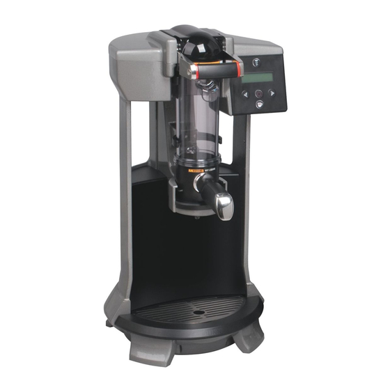
INTRODUCTION This equipment will brew a half-gallon batch of coffee into an awaiting dispenser. It can be easily confi gured for 120V 15 amp, 120/208V 20 amp or 120/240V 20 amp. The brewer may have a hot water faucet for allied beverage use. It is only for indoor use on a sturdy counter or shelf. CONTENTS Warranty ......................2 Contents ......................3... -
Page 4: Component Access
COMPONENT ACCESS This section provides procedures for testing and replacing various major components used in this brewer should service become necessary. Refer to Troubleshooting for assistance in determining the cause of any problem. WARNING - Inspection, testing, and repair of electri- cal equipment should be performed only by qualifi... -
Page 5: Upper Clamp Assembly Removal
4. Remove front panel. UPPER CLAMP ASSEMBLY REMOVAL 5. Disconnect silicon hose from vent valve. Discon- WARNING - Disconnect the brewer from the power nect 2 pin white/violet harness from Control Board source before the removal of any panel or the replace- J-11. -
Page 6: Upper Clamp Assembly Disassembly
UPPER CLAMP ASSEMBLY DISASSEMBLY WARNING - Disconnect the brewer from the power 3. Lift the sprayhead plug assembly out of the cap. source before the removal of any panel or the replace- ment of any component. 1. Remove c-clip, pivot shaft and brew chamber lifter. FIG. -
Page 7: Control Board
CONTROL BOARD Removal and Replacement: 1. Disconnect brewer from power source. 2. Disconnect the wires and harnesses from the control board. 3. Remove the six screws securing the control board to the bracket. 4. Secure the new control board to the bracket with six screws. -
Page 8: Cba Triac Map
CONTROL BOARD TRIAC MAP Triac: Load Component: Connector: Tank Heaters Heater Terminal/L2 Terminal Refi ll solenoid Red wire/White wire Rinse solenoid Brown wire/White wire FIG. 12-1 TRIAC MAP 42824 060611... - Page 9 DISPLAY/SWITCH BOARD Test Switches Procedure: Enter program mode by pressing both arrow but- tons until display reads "RECIPE CHANGES". Press and release the center program button until display reads "SERVICE TOOLS". Select "YES". Display will read "TEST OUTPUTS", select "NO". Display will read "TEST SWITCHES", select "YES".
-
Page 10: Refi Ll/Rinse Valves
REFILL/RINSE SOLENOID VALVES Removal and Replacement: 1. Disconnect the brewer from water & power sources. 2. Unscrew the brass elbow assembly from the valve. 3. Loosen (do not remove) the (2) M4 X 6mm screws RINSE REFILL securing the solenoid to the bracket. 4. -
Page 11: Air Pump Motors
AIR PUMP MOTORS Removal and Replacement: 1. Disconnect the brewer from the power source. 2. Remove nut and clamp. PRESS OUT 3. Disconnect harness and hose from the pump. PUMP TURBULENCE 4. Install new pump in reverse order. PUMP FIG. 15-1 PUMP MOTORS Location: The pump motors are located inside the top cover. -
Page 12: Tank Assembly
TANK ASSEMBLY HEATER RESISTANCE TEMPERATURE 1450W-100V 8.9-10.9 PROBE (3) 1450W-120V 32.8-40.1 1450W-230V 6.2- 7.6 TERMINAL TO SHEATH - INFINITE (OPEN) 3. Disconnect the wires from the tank heater terminals. 4. Check resistance value across tank heater terminals and compare to chart. If resistance is present as described, reconnect the wires, the tank heater is ok. -
Page 13: Temperature Probe
TANK ASSEMBLY TEMPERATURE PROBE (3) Removal and Replacement: 1. Disconnect the brewer from the power source. Location: 2. Disconnect the two pin connector from J2 on The temperature probe is inserted through the control board. tank lid assembly. 3. Remove clamp. Pull probe out of tubing. 4. -
Page 14: Schematic Wiring Diagrams
SCHEMATIC WIRING DIAGRAM TRIFECTA TANK t° LIMIT THERMOSTAT BLU/BLK TANK HEATER AIR PUMP MOTOR BREW INTLK SWITCH AIR VENT SOLENOID WHI/BLU WHI/BLU DISPLAY 1 WHI - Rx: 0 to +5vdc 2 BLK - Board Ground 3 RED - Tx: 0 to +3.4vdc... - Page 15 SCHEMATIC WIRING DIAGRAM TRIFECTA TANK t° BLU/BLK LIMIT LIMIT LIMIT THERMOSTAT THERMOSTAT THERMOSTAT THERMOSTAT TANK HEATER 230VAC AIR PUMP MOTOR BREW INTLK SWITCH AIR VENT SOLENOID WHI/BLU WHI/BLU DISPLAY 1 WHI - Rx: 0 to +5vdc 2 BLK - Board Ground 3 RED - Tx: 0 to +3.4vdc...
Need help?
Do you have a question about the trifecta and is the answer not in the manual?
Questions and answers