AMF S-100 Parts And Service Manual

AMF S-100 Parts And Service Manual

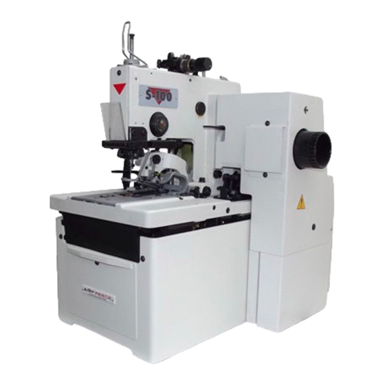
Electronic eyelet buttonhole machine
Hide thumbs Also See for S-100:
Table of Contents

Advertisement

Quick Links

S-311
MODEL
ELECTRONIC EYELET BUTTONHOLE
MACHINE
PARTS AND SERVICE MANUAL
MACHINE SERIAL No.
PART NUMBER 97. 1930.0.002
This manual is valid from the machine serial No.: N 190801
(version ACL: No. : N 190791)
AMF is trademark of AMF Group, Inc.
03/ 2 0 12

Advertisement

Table of Contents
loading

Summary of Contents for AMF S-100

  • Page 1 MACHINE PARTS AND SERVICE MANUAL MACHINE SERIAL No. PART NUMBER 97. 1930.0.002 This manual is valid from the machine serial No.: N 190801 (version ACL: No. : N 190791) AMF is trademark of AMF Group, Inc. 03/ 2 0 12...
  • Page 2 Authorized Distributor) will have the limited material warranty only. Only the defective material will be covered. Any charges associated with the use of an AMF Reece Technician or that of a Distributor to replace the defective part will be the customer’s responsibility.
  • Page 3 Warranty Registration Card (Please Fax or Mail immediately after installation) Note: All Warranty Claims Void, unless Registration Card on file at AMF Reece HQ Machine model number: (S100, S101, S104, S105, S 311, Deco, S4000 , EBS Mark II, ES505, etc) Manufacturer‘s serial or production number:...
  • Page 5: Table Of Contents

    S-311 TABLE OF CONTENTS A - INTRODUCTION 1. Basic information..........................1-1 2. Safety labels and device ......................... 1-2 3. General machine parts descriptions....................1-3 4. Specification ........................... 1-4 5. Buttonhole description........................1-6 6. Instructions for operator safety and maintenance of the machine S-311......... 1-7 7.
  • Page 6 S-311 TABLE OF CONTENTS 9. Setting the cutting ........................... 1-35 10. The round eye cutting setting ......................1-36 11. Service mode..........................1-37 12. Cycle mode ............................ 1-38 13. The buttonhole programming ......................1-39 14. The electronic system error messages..................... 1-40 15.
  • Page 7: Basic Information

    WARNING! Possible serious injury or machine damage. NOTICE! Possible injury or machine damage. We recommend that service workers from AMF Reece oversee the installation and initial training of your mechanics and operators. The most effective safety precaution is a well-managed safety program. Be sure those who use this machine are properly trained.
  • Page 8: Safety Labels And Device

    S-311 INTRODUCTION 2 . S A F E T Y L A B E L S A N D D E V I C E — — œ ™ š – Warning  Needle bar cover — Danger possible injury ž...
  • Page 9: General Machine Parts Descriptions

    S-311 INTRODUCTION 3 . G E N E R A L M A C H I N E PA R T S D E S C R I P T I O N S Main power switch Display Cutting activation button Table Air pressure regulator Control box...
  • Page 10: Specification

    S-311 INTRODUCTION 4. S P E C I F I C AT I O N S-311 Elektronic buttonhole machine with chain stitch is possible to use for men`s and women`s wear. Possible to use gimp thread, not in round eye. Machine type/model CT 22 - 32mm CT 14 - 24 mm...
  • Page 11 S-311 INTRODUCTION Machine type/model CT 14 - 32 mm Sewing speed 1000 to 2000 stitches/min (500 to 1000 rev/min of the drive shaft) The length 14 to 32 mm 10 to 36 mm of hole 0,5 to 2,0 mm (increments of 0,1 mm) Stitch Density 4 to 20 8 to 60...
  • Page 12: Buttonhole Description

    S-311 INTRODUCTION 5. B U T T O N H O L E D E S C R I P T I O N The first row of stitches ž ž ž ž ž The length of buttonhole – – – – – —...
  • Page 13: Instructions For Operator Safety And Maintenance Of The Machine S-311

    S-311 INTRODUCTION 6 . I N S T R U C T I O N S F O R O P E R AT O R S A F E T Y A N D M A I N T E N A N C E O F T H E M A C H I N E S - 311 When installing the machine the manufacturer recommends the minimum clearance mentioned above around the machine.
  • Page 14 S-311 INTRODUCTION When this machine is used incorrectly, or is incorrectly maintained, it can be dangerous. Everyone who uses this machine, or maintains this machine, must be completely familiar with this manual. C A U T I O N ! Perform all regular service as described in this manual.
  • Page 15: Special Device

    S-311 INTRODUCTION 7 . S P E C I A L D E V I C E 7.1. Working light – - order number 12.0008.4.875 7.2. Manual machine control — – - order number 03.5519.0.007 - allows to change the foot machine control for manual by switch installation on the table and changing the cables 7.3.
  • Page 16: B - Machine Assembly

    S-311 - MACHINE ASSEMBLY 1 . C O N T E N T O F T H E S H I P P I N G B O X – – – – – 1.1. If it is not mentioned otherwise during ordering, the shipping container usually contains: —...
  • Page 17 S-311 - MACHINE ASSEMBLY ˜ — ™ ˜ — 1-11 Revised 04/2007 e-mail: service@amfreece.cz; parts@amfreece.cz; website: www.amfreece.com Phones: +420 582 309 146 (Service); +420 582 309 286 (Spare Parts); Fax: +420 582 360 606...
  • Page 18: Connection Of The Machine Head With The Control Box

    S-311 - MACHINE ASSEMBLY 3. C O N N E C T I O N O F T H E M A C H I N E H E A D W I T H T H E C O N T R O L B O X 3.1.
  • Page 19 S-311 - MACHINE ASSEMBLY S-311 RDE - PNEUMATIC SYSTEM CONNECTION – ™ ™ ™ ™ ™ › ˜ ˜ ˜ ˜ ˜      4 bar 6 bar J8A1 – – – – – clamp feet up/down J8A2 ˜...
  • Page 20 S-311 - MACHINE ASSEMBLY S-311 AF - PNEUMATIC SYSTEM CONNECTION — – ™ ™ ™ ™ ™ › ˜ ˜ ˜ ˜ ˜ 4 bar      6 bar – – – – – clamp feet up/down J8A1 —...
  • Page 21 S-311 - MACHINE ASSEMBLY S-311 CT - PNEUMATIC SYSTEM CONNECTION — – ™ ™ ™ ™ ™ › ˜ ˜ ˜ ˜ ˜ 4 bar œ œ      6 bar J8A1 – – – – – clamp feet up/down —...
  • Page 22 S-311 - MACHINE ASSEMBLY S-311 LTT - PNEUMATIC SYSTEM CONNECTION — – ™ ™ ™ ™ ™ › ˜ ˜ ˜ ˜ ˜ 4 bar œ œ œ œ œ œ       6 bar – – – – – clamp feet up/down J8A1 —...
  • Page 23: Belt Tension

    S-311 - MACHINE ASSEMBLY ™ — 4. B E LT T E N S I O N 4.1. Lower belt – of sewing mechanism drive is installed on machine head pulley during the transport. To access this pulley : loosen screw — on drive belt cover ™, shift the cover aside and remove the cover.
  • Page 24: Power And Air Connection

    S-311 - MACHINE ASSEMBLY 5. P O W E R A N D A I R C O N N E C T I O N 5.1. Simple connection of air lines are made by quick connector. Socket 25 KEAK 13 (order number FESTO 151776 - marking KD 1/4 - S, order number RECTUS 38044) is used as standard.
  • Page 25: Thread Stand Installation

    S-311 - MACHINE ASSEMBLY 6. T H R E A D S TA N D I N S TA L L AT I O N 6.1. Put the thread stand together Picture 6.1. according to the drawing. 6.2. Position of the locking ring – allows assembly of the thread stand for various thickness of the table top.
  • Page 26: Lubrication

    S-311 - MACHINE ASSEMBLY 7. L U B R I C AT I O N 7.1. There is the fank for oil eycess on the machine –. 7.2. For oil tigthness and removal is important,that upper edge of the funnel — inserted to the holder ˜...
  • Page 27: C - Proper Application

    S-311 - PROPER APPLICATION 1 . P O W E R U P / H O M E P O S I T I O N 1.1. Turn the main power switch on – by turning clockwise to the „I“ position. 1.2.
  • Page 28: Needle Installation

    - PROPER APPLICATION 2 . N E E D L E I N S TA L L AT I O N Use needles AMF Reece 02.0505.0.111/113…. Nm 90 – 110), loading needle bard D = 2 mm. Needles 02.0558.1.112 are externally treated and needle shape is adapted for sewing thick material.
  • Page 29: Threading

    S-311 - PROPER APPLICATION 3 . T H R E A D I N G When threading, see the pictures below. For easy threading use threading devic – from accessories kit. It is possible to order the threading device —. Adjust the thread tension by knobs ˜, ™ according to sewing conditions.
  • Page 30 S-311 - PROPER APPLICATION 3.2. Lower thread - tilt back the rear cover – and lift the machine head — to thread the lower thread. – — lower thread AF, LTT 1-24 Revised 04/2007 e-mail: service@amfreece.cz; parts@amfreece.cz; website: www.amfreece.com Phones: +420 582 309 146 (Service); +420 582 309 286 (Spare Parts); Fax: +420 582 360 606...
  • Page 31 S-311 - PROPER APPLICATION 3.3. Gimp The appearance and quality of the buttonhole may be affected by one or more of the following: stitch density ( number of stitches in the first cutting space and the second row of stitches) tension of upper and lower thread number of stitches in the eye type of thread (size, etc.)
  • Page 32: D - Machine Controls

    S-311 - MACHINE CONTROLS 1 . O P E R AT I O N 1.1. With the machine in the home position, before sewing, the manufacturer recommends 3 minutes for warm up. 1.2. Be certain that the machine is threaded correctly see section C3, and required buttonhole appears on the display.
  • Page 33 S-311 - MACHINE CONTROLS ˜ ™ — š 1-27 Revised 04/2007 e-mail: service@amfreece.cz; parts@amfreece.cz; website: www.amfreece.com Phones: +420 582 309 146 (Service); +420 582 309 286 (Spare Parts); Fax: +420 582 360 606...
  • Page 34: Display Information

    S-311 - MACHINE CONTROLS Caution: Program for S311 machine is universal it allows to sew different buttonhole shapes only by changing the clamp plates. Please ensure that correct machine version (corresponding to clamp plate) is selected on the software. Be sure you understand the proper setting of the display: the eye shape, the sewing speed change, machine modification change, the cutting space setting and cycle mode use.
  • Page 35: The Buttonhole Shape Setting

    S-311 - MACHINE CONTROLS 3 . T H E B U T T O N H O L E SHAPE S E T T I N G To set the buttonhole, it is necessary to set the parameters of eye, the first and the second row of stitches and the bar.
  • Page 36: Buttonhole Parameters Adjustment

    S-311 - MACHINE CONTROLS 4. BUTTONHOLE PARAMETERS ADJUSTMENT Return to main display Table feeding in first and Electroniccaly First and second row of second row of stitches Buttonhole lenght Stitches density adjustable bite stitches adjustment (range 0 - 100) (depends on machine type) (range 0.5 - 2.0 mm) size (range ±...
  • Page 37 S-311 - MACHINE CONTROLS 5. BUTTONHOLE PARAMETERS ADJUSTMENT Return to main display Return to main display Return to previous display Number of stitches in round end (range 4 - 20 stitches) Number of removed or added stitches Number of overlapped stitches (range ±...
  • Page 38 S-311 - MACHINE CONTROLS 6. SEWING SPEED SETTING Return to main display Number of stitches, Number of stitches, Number of stitches, which are sewn by slow which are sewn with which are sewn by slow Sewing speed in double density (locking speed at buttonhole speed at buttonhole Sewing speed in the first and...
  • Page 39: Sewing Speed Setting For The Round Eye (Af, Rde)

    S-311 - MACHINE CONTROLS 7. SEWING SPEED SETTING FOR THE ROUND EYE (AF, RDE) Return to main display Number of stitches which are sewn by slow speed Number of stitches which at buttonhole start (range are sewn by slow speed Sewing speed 0 - 9 stitches, speed at buttonhole finish...
  • Page 40: Buttonhole Counters

    S-311 - MACHINE CONTROLS 8. BUTTONHOLE COUNTERS Return to main display Total number of cycles (buttonholes) Button for counting upward RESET button (SET) The counter range adjustment Button for counting (range 0 - 9999) descending EXPLANATION: A specific number can be entered in the counter which can be counted on ascending or descending form.
  • Page 41: Setting The Cutting

    S-311 - MACHINE CONTROLS 9. SETTING THE CUTTING Cutting indication Cut after Cut before sewing (CA) sewing (CB) cutting Return to main display Cutting space, distance Stitches distance from between first and cut to inner stitches of Buttonhole cut Buttonhole cut second row of stitches the eye correction in X axis...
  • Page 42 S-311 - MACHINE CONTROLS 10. ROUND EYE CUTTING SETTING No cutting Cut before sewing (CB) Cut after sewing Return to main display Buttonhole cut Buttonhole cut correction in X axis correction in Y axis (range ± 1.5 mm) (range ± 1.5 mm) 1-36 Revised 04/2007 e-mail: service@amfreece.cz;...
  • Page 43: Service Mode

    Button for machine type setting I/O TEST Return to previous Return to previous display display Button for copy saving Return to previous Logo AMF Reece Button for display Button AMF Reece service Pocket effect technicians * ON/OFF Button Only service code...
  • Page 44: Cycle Mode

    S-311 - MACHINE CONTROLS 12. C Y C L E M O D E It is possible to set the type and the number of buttonholes which will be sewn in one sewing cycle. C A U T I O N : Modification AF - it is necessary to use the same cutting length for all buttonholes in one cycle.
  • Page 45 S-311 - MACHINE CONTROLS 13. BUTTONHOLE PROGRAMMING 1. Press the button in the right bottom corner on the screen.The numerical display appears on the screen. Choose the buttonhole number 1 and press 2. Program the buttonhole shape according to the sections - D3, D4, D5. 3.
  • Page 46: Manual Cut Mode

    S-311 - MACHINE CONTROLS 14. E L E C T R O N I C S Y S T E M E R R O R M E S S A G E S If an error message appears on the display, press it – – – – – The screen — — — — — with a description and a correction of an error message appears on the display (see Troubleshooting).
  • Page 47: E - Standard Machine Adjustment

    S-311 - STANDARD MACHINE ADJUSTMENT W a r n i n g : - before making any adjustments, turn the main power switch off - careless adjustment can cause damage to electronic and mechanical parts C a u t i o n : - always maintain good safety standards - where possible, remove the sewing needle before making mechanical adjustments 1 .
  • Page 48: The Sewing Drive Sensor Plates Adjustment

    S-311 - STANDARD MACHINE ADJUSTMENT 2. THE SEWING DRIVE SENSOR PLATES ADJUSTMENT It is important that the sensor plates of the sewing drive are properly adjusted. To access these plates, remove the right side cover according to the section B4.The sensors are adjusted from the manufac- turing factory and are marked with the colour.
  • Page 49: The Bedplate Home Position Adjustment

    BQ3 š for Y. Sensor plate screws are painted from the manufacturer, and only a service technician from AMF REECE can perform this operation during the guarantee period . 3.1. Adjust the sensor plate ™ (BQ2)  after loosening the screws, ˜ to approximately 14 mm.
  • Page 50: The Race Mechanism Adjustment

    › is locked by paint from the manufacturer, that is why only a service technician from AMF REECE can perform this operation during the guarantee period. Make sure there is the buttonholl without eye on the display, stitches inclination 0°, cutting distance 0.0, see section D3,D6.
  • Page 51: The Sewing Mechanism Height Control

    S-311 - STANDARD MACHINE ADJUSTMENT 5. THE SEWING MECHANISM HEIGHT CONTROL Before any other adjustment, we recommend to check, if the height of the sewing mechanism of the loopers, spreaders and stitching plate is adjusted properly. 5.1. The height 6,5 mm of the sewing mechanism support –, from the surface for the anvil can be readjusted by inserting or removing the washer —...
  • Page 52: Mechanism Adjustment For Material Clamping

    S-311 - STANDARD MACHINE ADJUSTMENT 6. MECHANISM ADJUSTMENT FOR MATERIAL CLAMPING WA R N I N G ! Before doing any adjustments, disconnect the air supply and deflate the test of compressed air in the ˜ machine. The basic clamp plates adjustment – with clamp feet — is possible to modify after removing from the machine.
  • Page 53: Spreading Of A Material

    S-311 - STANDARD MACHINE ADJUSTMENT 7. S P R E A D I N G O F A M AT E R I A L Loose fabric, especially thin, can cause missing stitches unless it is spread. The machine is equipped by a mechanism to control the extent of fabric spreading.
  • Page 54: Adjustment Of The Cutting Mechanism

    S-311 - STANDARD MACHINE ADJUSTMENT 8. A D J U S T M E N T O F T H E C U T T I N G M E C H A N I S M Caution : Before doing the adjustment, it is necessary that the parameters, especially the cutting space and correction was adjusted on 0 - section D9, buttons The cut position is given by the point of departure of the stepping motors adjustment.
  • Page 55 S-311 - STANDARD MACHINE ADJUSTMENT 8.3. The knife in the axis X in the anvil › loosing the screws š and change safely the position, to the right or to the left. Tighten the screws. 8.4. The knife stop in the anvil › adjust for 70 mm after loosing the screws œ. œ...
  • Page 56 S-311 - STANDARD MACHINE ADJUSTMENT 8.7. The knife attachment into cutting steel with the screw needs to be done only manualy! The tool is used only for loosing too tight setting screw. Warning: When changing the knife, pay attention to the tightening the screw. 1-50 Revised 06/2007 e-mail: service@amfreece.cz;...
  • Page 57: Setting The Needle Bar Height

    S-311 - STANDARD MACHINE ADJUSTMENT 9. S E T T I N G T H E N E E D L E B A R H E I G H T 9.1. Remove the machine head front cover. – — 9.2.
  • Page 58: Spreader And Looper Cam Adjustment

    S-311 - STANDARD MACHINE ADJUSTMENT 10. S P R E A D E R A N D L O O P E R C A M A D J U S T M E N T Locate the cam – on the holder gauge line —...
  • Page 59: Spreaders Adjustment

    S-311 - STANDARD MACHINE ADJUSTMENT 1 2. S P R E A D E R S A D J U S T M E N T To reach this, rotate the hand wheel. 12.1. Adjust the right spreader Ÿ to the right looper edge ž, the left spreader with the groove on the hole of the left looper ›.
  • Page 60: Adjustment Of The Bite Mechanism

    S-311 - STANDARD MACHINE ADJUSTMENT 13. A D J U S T M E N T O F T H E B I T E M E C H A N I S M S 311 machine is equipped with a mechanism to change electronically the width of buttonhole seaming. The mechanism can be set up for 2 main seaming widths –...
  • Page 61: Upper Thread Trimming Mechanism - Af/Ltt

    S-311 - STANDARD MACHINE ADJUSTMENT 1 4. U P P E R T H R E A D T R I M M I N G MECHANISM - AF/LTT 14.1. After installation of the holder with trimming knife – adjust the trimming knife after loosening the screw ˜...
  • Page 62: Adjustment Of The Upper Thread Pick-Up Height

    S-311 - STANDARD MACHINE ADJUSTMENT A D J U S T M E N T O F T H E U P P E R T H R E A D P I C K - U P H E I G H T Is used on the LTT machine as standard.
  • Page 63: Upper Trimming And Lower Interception - Ct

    S-311 - STANDARD MACHINE ADJUSTMENT UPPER TRIMMING AND LOWER INTERCEPTION - CT with trimming knife –, adjust the height of the thread 16.1 After installation of the thread retainer retainer to within 0.2 mm of the top of the throat plate. 16.2.
  • Page 64 S-311 - STANDARD MACHINE ADJUSTMENT 16.7. Shears adjustment There is a trimming mechanism on the right clamp plate. Loosen the screw ž and adjust the center of the roller  to 43 mm from the edge of the clamp plate. Tighten the screw ž.
  • Page 65 S-311 - STANDARD MACHINE ADJUSTMENT 16.9. Elektronic adjustment of the CT parameters a) Electronic adjustment of trimmed threads tails Standard adjustment 15,2 Increase parameters on flexible threads 15,2 b) Electronic adjustment of the clamp feet elevation during the lower thread and gimp trimming - Time for the clamp feet elevation before trimming knives activation (range 0 –...
  • Page 66: Mechanismus Adjusting For Ct Gimp

    S-311 - STANDARD MACHINE ADJUSTMENT 17. MECHANISMUS ADJUSTING FOR CT GIMP Gimp auxiliary stretcher adjusting: Adjusting performed as follows: the stretcher slightly holds the gimp and when turning the race in the end of buttonhole where the gimp does not run from the coil but the thread end is shorter after the throat plate trimming Over tension in stretcher might cause the buttonhole deformation in eye.
  • Page 67: The Trimming Mechanism Adjustment - Ltt

    S-311 - STANDARD MACHINE ADJUSTMENT 18. TH E TR I M M I N G ME C H A N I S M AD J U S T M E N T - LT T The lower thread and gimp thread are trimmed before the clamp feet are raised. –...
  • Page 68 S-311 - STANDARD MACHINE ADJUSTMENT knives adjustment - LTT a.1. Loosen the screw a.2. Turn the knife œ in direction A and adjust the Blade section position of the guide plate so that the lower edge is aligned with knife edge œ . of the guide plate a.3.
  • Page 69 S-311 - STANDARD MACHINE ADJUSTMENT lower thread clamp fixing plate adjustment - LTT b.1. Loosen two screws b.2. Turn the knife œ in direction A to align the fixing knife face › with knife blade section Blade section edge œ. Then make as small as possible clearance C (approximately 1mm) between the thread catching plate –...
  • Page 70: Setting The Thread Tension And Thread Draw Off

    S-311 - STANDARD MACHINE ADJUSTMENT 19. S E T T I N G T H E T H R E A D T E N S I O N A N D T H R E A D D R AW O F F A thread tension change may be needed if the thread and fabric change.
  • Page 71: Voltage Guard

    S-311 - STANDARD MACHINE ADJUSTMENT 2 0 . VO LTAG E G UA R D The voltage guard - relay HRN-35 (VC1) as an extra accessories is placed in the machine control box. It is adjusted and sealed from a manufacturer. If the supply voltage is in the required range, the green LED Un indicates it on the voltage monitoring relay.
  • Page 72: F - Machine Maintenance

    S-311 - MACHINE MAINTENANCE Warning: - Check electrical cables for damage. - Check if the safety covers are in a good condition. Order or replace damaged covers. - Keep your hands out from the needle space and cutting mechanism. - Do not modify the machine in any way, which can eliminate its safety parts. Caution: - Do not neglect periodic maintenance.
  • Page 73 S-311 - MACHINE MAINTENANCE 1.6. Using a screwdriver, loosen the locks on the control box door. Using a wrench, loosen 4 screws on the fan rack C A U T I O N ! When loosening the last screw, hold the fan by hand inside the control box to prevent it from dropping into the control box.
  • Page 74: Periodic Maintenance

    S-311 - MACHINE MAINTENANCE 2 . P E R I O D I C M A I N T E N A N C E once a day (8 hours of operation) cleaning of the sewing mechanism area and inner frame of the machine once a week (40 hours of operation) visual check - external and internal mechanism...
  • Page 75: Scheme Of The Lubrication Distribution

    S-311 - MACHINE MAINTENANCE 3 . S C H E M E O F T H E L U B R I C AT I O N D I S T R I B U T I O N The machine is equipped with needle and ball bearings, which in combination with two lubrication circuits significantly decrease required maintenance.
  • Page 76: Machine Lubrication

    S-311 - MACHINE MAINTENANCE 4 . M A C H I N E L U B R I C AT I O N 4.1. It is necessary to remove preserve oils and lubricate the places shown below before the machine is switched on for the first time or after a long idle period. Use ESSO TERESSO 32 or similar quality.
  • Page 77 S-311 - MACHINE MAINTENANCE 4.5. Remove the feet plate according to the part E2, point 2 and oil the bushing œ and , rod of the spreader ž and Ÿ, stud and shafts , by one or two drops of oil to the marked places on the drawing shown and on the machine are those places marked by red dors.
  • Page 78: Machine Disposal

    S-311 - MACHINE MAINTENANCE 5 . M A C H I N E D I S P O S A L 5.1. To ensure machine ecological disposal it is necessary to remove especially nonmetallic parts from the machine. To take these parts out, it is necessary to perform the partial dismantling of the machine, remove covers, dismantle the machine arm and remove the frame.
  • Page 79: G - Documentation

    S-311 - DOCUMENTATION PNEUMATIC DIAGRAM 1-73 Revised 02/2009 e-mail: service@amfreece.cz; parts@amfreece.cz; website: www.amfreece.com Phones: +420 582 309 146 (Service); +420 582 309 286 (Spare Parts); Fax: +420 582 360 606...
  • Page 80: Electrical Diagram

    S-311 - DOCUMENTATION ELECTRICAL DIAGRAM 1-74 Revised 02/2009 e-mail: service@amfreece.cz; parts@amfreece.cz; website: www.amfreece.com Phones: +420 582 309 146 (Service); +420 582 309 286 (Spare Parts); Fax: +420 582 360 606...
  • Page 81 S-311 TROUBLESHOOTING TABLE OF CONTENTS SYMPTOM POSSIBLE CAUSE PROBABLE SOLUTION Page 1. INTRODUCTION ..................2-2 2. FAULTS WITHOUT ERROR MESSAGES ........... 2-3 3. THE ELECTRONIC SYSTEM ERROR MESSAGES ......2-6 4. ELECTRICAL FAULTS ................2-9 Revised 06/2007 e-mail: service@amfreece.cz; parts@amfreece.cz; website: www.amfreece.com Phones: +420 582 309 146 (Service), +420 582 309 286 (Spare Parts);...
  • Page 82 S-311 TROUBLESHOOTING Wa r n i n g ! Inspect the machine on a regular basis and use only quality parts. The manufacturer recommends using original AMF Reece parts, especially needles, loopers, spreaders, and throat plates. SYMPTOM POSSIBLE CAUSE PROBABLE SOLUTION 1 .
  • Page 83 S-311 TROUBLESHOOTING 2 . FA U LT S W I T H O U T E R R O R M E S S A G E S SERVICE SYMPTOM POSSIBLE CAUSE PROBABLE SOLUTION SYMPTOM POSSIBLE CAUSE PROBABLE SOLUTION SECTION Thread breakage.
  • Page 84 S-311 TROUBLESHOOTING SERVICE POSSIBLE CAUSE SYMPTOM PROBABLE SOLUTION SECTION SYMPTOM POSSIBLE CAUSE PROBABLE SOLUTION The lower thread is Choked slot in throat plate. Big clearance between holder not caught in the page 1-56 Adjust the clearance between and throat plate. thread retainer after the holder and throat plate sewing the...
  • Page 85 S-311 TROUBLESHOOTING SERVICE POSSIBLE CAUSE SYMPTOM PROBABLE SOLUTION SECTION SYMPTOM POSSIBLE CAUSE PROBABLE SOLUTION Indexer Air supply is not connected. Check air supply. clamp plates do not close. Clamp plates do not Check air pressure Low pressure. (0,5 min. Bar) E1-S-311+I. hold the material properly.
  • Page 86 S-311 TROUBLESHOOTING 3 . T H E E L E C T R O N I C S Y S T E M E R R O R M E S S A G E S If an error message appears on the display (see picture –), press it. The screen with a description and a correction of an error message appears on the display (see picture —).
  • Page 87 S-311 TROUBLESHOOTING POSSIBLE CAUSE PROBABLE SOLUTION SYMPTOM Check R axis home sensor BQ3 and R axis positioning error. stepper motor. Check I axis home sensor BQ10, I axis positioning error. BQ11 and stepper motor. T axis positioning error. Check T axis home sensor BQ5 and stepper motor.
  • Page 88 S-311 TROUBLESHOOTING SYMPTOM POSSIBLE CAUSE PROBABLE SOLUTION ACL-LP lapel cutting lenght Check the lapel cutting length parameter error. according to moveable support plate range of machine type ACL-LP lapel cutting parameters Check the lapel cutting length and error. position according to moveable support plate range of machine type.
  • Page 89 Cable from the display Check the display connection disconnected Replace display or control units, Display or its control damaged call AMF Reece Service When sewing operation Replace fuse PN 12.0008.4.664 Fuse F4 failure (T10A) started, motor does not operate. Frequency inverter Replace contactor 12.0008.4.833...
  • Page 90 S-311 TROUBLESHOOTING SYMPTOM POSSIBLE CAUSE PROBABLE SOLUTION Replace contactor 12.0008.4.833 When sewing operation Contactor KM1 damaged started, air valves do not operate. The air pressure correct. Replace contactor 12.0008.4.833 Inadequate contact of contactor Incorrect function of the air Check the main power supply with KM1,or sockets X4 valves socket X4...

This manual is also suitable for:

S-101S-104S-105S-311S-4000Deco ... Show all

Table of Contents