Table of Contents
Advertisement
Quick Links
Advertisement
Chapters
Table of Contents

Subscribe to Our Youtube Channel
Related Manuals for AMF ES-505


Summary of Contents for AMF ES-505
- Page 1 ES-505 MODEL ELECTRONIC EYELET BUTTONHOLE MACHINE PARTS AND SERVICE MANUAL MACHINE SERIAL No: 97.1500.0.003 PART NUMBER This manual is valid from the machine Serial No.: R5050058 R5050059 R5050060 R5050061 AMF is trademark of AMF Group, Inc. 12 / 2017...
- Page 3 ES-505 MODEL ELECTRONIC EYELET BUTTONHOLE MACHINE PARTS AND SERVICE MANUAL MACHINE SERIAL No: 97.1500.0.003 PART NUMBER This manual is valid from the machine Serial No.: R5050058 R5050059 R5050060 R5050061 AMF is trademark of AMF Group, Inc. 12 / 2017...
- Page 7 However, the satisfaction and goodwill of our customers are of pri- mary concern to AMF Reece, Inc. In the event that a warranty matter is not handled to your satisfaction, please contact AMF Reece office:...
- Page 9 Warranty Registration Card (Please Fax or Mail immediately after installation) Note: All Warranty Claims Void, unless Registration Card on file at AMF Reece HQ Machine model number: (S101, S100, S104, S105, S311, Decostitch, S4000, EBS Mark II, etc) Manufacturer‘s serial or production number: Installation Site Information: Customer‘s Name:...
-
Page 11: Table Of Contents
4.2.1. Models of machines with ultraflex: ...................... 1-8 4.2.2. Use of the machine: ..........................1-9 4.3. Indexer model ............................1-10 4.3.1. Models of es-505 indexer machine ..................... 1-10 4.3.2. Use on the machine ..........................1-10 5. TECHNICAL CONDITIONS ........................1-11 5.1. - Page 12 ES-505 TABLE OF CONTENTS 2. PROGRAMMING ............................. 1-36 2.1. Buttonhole program options ........................1-36 2.2. Program name options ........................... 1-37 2.3. Setting buttonhole parameters ....................... 1-38 2.3.1. Setting eye parameters ........................1-38 2.3.2. Setting parameters round buttonhole ....................1-39 2.3.3. Setting parameters of first and secod raw of stitches ................1-40 2.3.4.
- Page 13 ES-505 TABLE OF CONTENTS 5.1. Setting up sensor screen bq1 ......................... 1-73 5.2. Setting up sensor screen bq8 ........................ 1-73 6. SETTING BED PLATE ..........................1-74 7. SETTING UP TURNING MECHANISM ....................1-75 8. CHECKING SEWING MECHANISM HEIGHT ..................1-76 9.
- Page 14 ES-505 TABLE OF CONTENTS 1.2.1. Control box ............................1-111 1.2.2. Draining lubrication oil out ........................1-111 1.2.3. Eye safety cover ..........................1-111 1.2.4. Lubrication ............................1-111 1.2.5. Battery replacement ..........................1-112 2. MAINTENANCE LIST ..........................1-113 3. MACHINE DISPOSAL ..........................1-113 H-DOCUMENTATION 1.
-
Page 15: A-Introduction
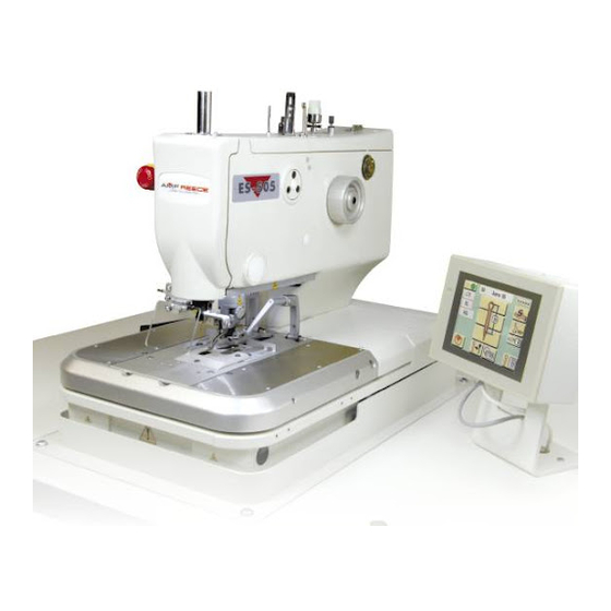
The second part is to provide information to help with ordering spare parts for this machine. ES-505 is electronic apparel buttonhole machine. It is used for sewing all types of buttonholes on different kinds of fabrics and with options of cut before (CB) or cut after (CA) sewing. The machine can sew chain stitch with double or single thread and optionally with gimp. -
Page 16: Safety Instructions
Do not put the machine into operation until you have read all manuals supplied with the machine and you understood each function and operation! We recommend AMF Reece servicemen to be present at the machine installation and initial training of your mechanics and operators. -
Page 17: Delivery Safety Instructions
ES-505 A - INTRODUCTION 2.3. DELIVERY SAFETY INSTRUCTIONS When unwrapping the machine, follow the marks and symbols on the box and wrapping. Visible damages of the consignment caused during shipment must be reported to the freight forwarder immediately. Check the content of the consignment with the order and inform the manufacturer on any discrepancies. -
Page 18: Safety And Instruction Labels On The Machine
ES-505 A - INTRODUCTION 2.6. SAFETY AND INSTRUCTION LABELS ON THE MACHINE Released: 01/2018 E-mail: service@amfreece.cz; webside: amfreece.com Phone: +420 582 309 146; Fax: +420 582 360 606... - Page 19 ES-505 A - INTRODUCTION Released: 01/2018 E-mail: service@amfreece.cz; webside: amfreece.com Phone: +420 582 309 146; Fax: +420 582 360 606...
-
Page 20: Colour Marks On The Machine
ES-505 A - INTRODUCTION 3. COLOUR MARKS ON THE MACHINE Loosening and dismantling this joint is significant hit to the adjustment of the mechanism, which was done at the manufacturer YELLOW MARKS during assembly and final sew off. After such interference into the... -
Page 21: General Machine Parts Description
ES-505 A - INTRODUCTION 4. GENERAL MACHINE PARTS DESCRIPTION 4.1. BASIC MODEL Sewing Head Thread Stand Stand Front Cover Foot Pedal Control Box Upper Cover Eye Guard Motor Rare Cover Hand Wheel Table Bed plate Emergency Stop Button Activation ofimediate Button... -
Page 22: Ultraflex Model
ES-505 A - INTRODUCTION 4.2. ULTRAFLEX MODEL Elektronic apparel buttonhole machine with sliding cutting steel enables sewing buttonholes withing the range of 13- 30 mm and wits the cut 6 - 30 mm without the change the cutting steel. This device is called ULTRAFLEX (formerly know as ACL). -
Page 23: Use Of The Machine
ES-505 A - INTRODUCTION 4.2.2. Use of the machine: Slidding Block Mechanism Motor Sensor Pressure changing valve 0,5 MPa 0,25 MPa Regulator cutting lapel buttonhole cutting pressure (0,25 MPa) Manometer Released: 01/2018 E-mail: service@amfreece.cz; webside: amfreece.com Phone: +420 582 309 146; Fax: +420 582 360 606... -
Page 24: Indexer Model
The electronic eylet buttonhole machine with Indexer enables automatic sewing of buttonholes which can be specified in number and distance between them. 4.3.1. Models of ES-505 Indexer machine a) AF+I This model is designed to be used for sewing single thread chain stitch buttonholes on ready-tailored jacket sleeves. -
Page 25: Technical Conditions
ES-505 A - INTRODUCTION 5. TECHNICAL CONDITIONS 5.1. BASIC MODEL 1-11 Released: 01/2018 E-mail: service@amfreece.cz; webside: amfreece.com Phone: +420 582 309 146; Fax: +420 582 360 606... -
Page 26: Ultraflex Model
ES-505 A - INTRODUCTION 5.2. ULTRAFLEX MODEL 1-12 Released: 01/2018 E-mail: service@amfreece.cz; webside: amfreece.com Phone: +420 582 309 146; Fax: +420 582 360 606... -
Page 27: Indexer Model
ES-505 A - INTRODUCTION 5.3. INDEXER MODEL Machine models AF + I CT14 - 26 mm + I Aplication Jacket Sleeve Jacket Sleeve / Jeans Fly Front Stitch Type Single chainstitch Double chainstitch with or without gimp Number Of Buttohnhole 1 –... -
Page 28: Terminology Used To Describe Buttonhole Parts
ES-505 A - INTRODUCTION 6. TERMINOLOGY USED TO DESCRIBE BUTTONHOLE PARTS First raw of stitches Number of stitches in eye Number of stitches in round end Second raw of stitches Stitch density Number of stitches in cross bar Eye area... -
Page 29: Ultraflex Model
ES-505 A - INTRODUCTION 7.2. ULTRAFLEX MODEL The table shows cutting options for buttonholes (with and without eye) with cross bar. Both cutting options can be used for buttonholes with a different bar type (fly bar, cross bar and round end) or without a bar (open end buttonhole). -
Page 30: Special Accessories
ES-505 A - INTRODUCTION 8. SPECIAL ACCESSORIES Working light 12.0008.4.875 Manual start control Pocket holder 03.5515.0.015 03.5515.0.036 Thread nipper Optical sensor for Ultraflex Two-position foot pedal 03.5515.0.019 model/lapel optical 12.0010.4.238 03.5515.0.018 1-16 Released: 01/2018 E-mail: service@amfreece.cz; webside: amfreece.com Phone: +420 582 309 146; Fax: +420 582 360 606... -
Page 31: B-Machine Instalation
ES-505 B - MACHINE INSTALATION 1. CONSIGNMENT CONTENT When unpacking the machine, it is necessary to follow the signs on the package. If not specified otherwise at the time of the order, the consignment consists of: • Assembled machine with electroinstallation on the stand •... -
Page 32: Placing Machine
ES-505 B - MACHINE INSTALATION 3. PLACING MACHINE Minimal safety distances A [m] B [m] C [m] D [m] 1 - wall, machines 2 - side, table 3 - service path 4 - second machine operator 4. THREAD STAND INSTALLATION See the picture for Thread stand assembly. -
Page 33: Checking Oil Tank
ES-505 B - MACHINE INSTALATION 5. CHECKING OIL TANK 5.1. To Cheb oil and to install drainage for excess oil, use the tank 5.2. Screw the tankinto the bottom area of the frame 5.3. Pour out the tank if full... -
Page 34: Connecting Machine With Electricity And Air Distribution
ES-505 B - MACHINE INSTALATION 6. CONNECTING MACHINE WITH ELECTRICITY AND AIR DISTRIBUTION 6.1. Air adjustment unit can be easily connected with the safety quickjoint socket. We normaly recommend using the socket 25 KE AK 13 (order.no. FESTO 151 776 označen KD -1/4, order.no.RECTUS 38044) -
Page 35: C-Proper Usage
1.1. ADJUSTING NEEDLE Use AMF Reece needles only. Order.no.02.0579.1.111 (NEEDLE 579 - 100 Nm GEBEDUR). Diameter of the needle inlet in the needle bar is2 mm. Needles are surface finished and their shape suits thick fabric sewing. It is not possible to use thicker needles for standard stitch plates. -
Page 36: Threading Upper Thread
ES-505 C - PROPER USAGE 1.3. THREADING UPPER THREAD For threading see pictures below. To make threading easier use threading tool which is part of the machine can be ordered (order no 12.0008.6.200). Thread tension (see E 29 section) needs to be accessories. -
Page 37: Threading Bottom Thread
ES-505 C - PROPER USAGE 1.4. THREADING BOTTOM THREAD See pictures below. Model CT Model LTT Model AF 1-23 Released: 01/2018 E-mail: service@amfreece.cz; webside: amfreece.com Phone: +420 582 309 146; Fax: +420 582 360 606... -
Page 38: Gimp Draw Off
ES-505 C - PROPER USAGE 1.5. GIMP DRAW OFF See pictures below. Model AF Model LTT, CT 1-24 Released: 01/2018 E-mail: service@amfreece.cz; webside: amfreece.com Phone: +420 582 309 146; Fax: +420 582 360 606... -
Page 39: Lubrication
ES-505 C - PROPER USAGE 2. LUBRICATION CAUTION! Before you start lubricating machine mechanisms, switch off power supply and air inlet from the machine! Note: To lubricate mechanisms in the machine use the recommended oil Esso Terestic T68 or Mobil Terestic T68 only. -
Page 40: Lubricating Important Parts
ES-505 C - PROPER USAGE 2.2. LUBRICATING IMPORTANT PARTS Before you use the machine for the first time or if you have not used it for some time, check and Needle bar area lubricate palces shown in pictures. These places are not lubricated from the tanks and therefore it is necessary to check them every month. -
Page 41: Putting Machine Into Home Position For Sewing
ES-505 C - PROPER USAGE 3. PUTTING MACHINE INTO HOME POSITION FOR SEWING 3.1 Start the main switch by turning it clockwise into the position I. 3.2 Display gets activated and illuminated. The screen shows information on manufacturer and numbers of programs downloaded into the machine. -
Page 42: Loading Fabric
ES-505 C - PROPER USAGE 4. LOADING FABRIC 4.1 Bring the machine into home position see section C3 (with clamps up). 4.2 Adjust the distance of the buttonhole from fabric edge: Position of the screw shows approximate distance of the buttonhole from the fabric edge. Loosen... -
Page 43: Sewing Buttonhole
ES-505 C - PROPER USAGE 5. SEWING BUTTONHOLE Bring the machine into the home position to sew (as in section C3 of this part). Before starting sewing, it is recommended that the machine is left is such state for 3 minutes to warm up. -
Page 44: Broken Thread
ES-505 C - PROPER USAGE 6. BROKEN THREAD If thread gets broken during buttonhole sewing, follow the instructions: 6.1 Press down the left pedal while sewing. The machine stops and the display changes screens . The workpiece is clamped down and held by the clamp feet, the needle moves into the upper dead point. -
Page 45: D-Machine Controls
D before setting up the parameters. • ES-505 machine uses a universal program that enables various sewing of buttonholes just changing clamp plates. Please make sure that the clamp plates in the machine correspond with the machine modification set up. - Page 46 ES-505 D - MACHINE CONTROLS Button/ Current/ following Screen name/ Parameter setting Chapter icon icon name screen 1 Button hole 1 Buttonhole program number Numeric keyboard D 2.1. 2700 List of programs Buttonhole program number D 2.1. screen 1 Button hole 1...
- Page 47 ES-505 D - MACHINE CONTROLS Current / following Screen name - Button - Parameter setting Chapter icon name icon screen Round buttonhole Cutting types cutting parameters Correction of cut in X / Y axes D 2.5. screen Cutting time delay...
-
Page 48: Buttons And Icons Commonly Used
ES-505 D - MACHINE CONTROLS 1.2. BUTTONS AND ICONS COMMONLY USED Bellow mentioned buttons and icons are routinely seen on display screens. They are not described in following chapters. Please study carefully their meanings before initioal programming. Button Name of the button... -
Page 49: Before Initial Programming
ES-505 D - MACHINE CONTROLS 1.3. BEFORE INITIAL PROGRAMMING WARNING! • Before initial sewing make sure you understand how to set up the display: eye shape, sewing speed and how to change it, machine modification, cutting space, cycling mode. •... -
Page 50: Programming
ES-505 D - MACHINE CONTROLS 2. PROGRAMMING 2.1. BUTTONHOLE PROGRAM OPTIONS Set parameters are automatically and continuously saved during the whole programming process. If you wish to modify a program, which has been already saved in the machine memory, proceed the same way as when saving the program or use the screen with program listing. -
Page 51: Program Name Options
ES-505 D - MACHINE CONTROLS 2.2. PROGRAM NAME OPTIONS To make individual programs easier to find it is possible to save each program under a name. A program name can have a combination of maximum 14 alphanumeric symbols. Procedure: Press the button on the main screen. -
Page 52: Setting Buttonhole Parameters
ES-505 D - MACHINE CONTROLS 2.3. SETTING BUTTONHOLE PARAMETERS Buttonhole parameter screen enable setting of buttonhole parameters as well as the way of their sewing. Before the initial sewing of the buttonhole, it is necessary to set parameters of the eye, first and second raw of stitches and the ending (type of bar). -
Page 53: Setting Parameters Round Buttonhole
ES-505 D - MACHINE CONTROLS 2.3.2. SETTING PARAMETERS ROUND BUTTONHOLE Press the button on the main screen of the round buttonhole. Round buttonhole parameters screen comes up at AF model. Here you can choose a buttonhole without eye, with eye or round buttonhole (buttons Press the button and the round buttonhole is highlighted active. -
Page 54: Setting Parameters Of First And Secod Raw Of Stitches
ES-505 D - MACHINE CONTROLS 2.3.3. SETTING PARAMETERS OF FIRST AND SECOND ROW OF STITCHES Here you set the buttonhole length and stitch features – density, bite and position of stitches. Press the button on the main screen. First and second raw of stitches screen comes up. -
Page 55: Buttonhole Ending Setup
ES-505 D - MACHINE CONTROLS 2.3.4. BUTTONHOLE ENDING SETUP Buttonhole can have open end, fly bar, cross bar or round end – see section A 7.1. For each ending setup follow the instructions in the chapters bellow. 2.3.4.1. SETTING BUTTONHOLE OPEN END Press the button on the main screen. -
Page 56: Setting Buttonhole Cross Bar
ES-505 D - MACHINE CONTROLS 2.3.4.3. SETTING BUTTONHOLE CROSS BAR Press the button on the main screen. The screen shows possible buttonhole ends. Use buttons to select the required buttonhole end. Press the button , which stand for the cross bar of an buttonhole. - Page 57 ES-505 D - MACHINE CONTROLS 2.3.4.5. SETTING ROUND END OF BUTTONHOLE WITH SEWING START IN BAR Press the button on the main screen. The screen shows possible buttonhole ends. Use buttons to select the required buttonhole end. Press the button , which stand for the round end of an buttonhole with sewing starting in the bar.
-
Page 58: Setting Buttonhole Cutting
ES-505 D - MACHINE CONTROLS 2.4. SETTING BUTTONHOLE CUTTING Cutting options can be set up with the buttons as follows. Apart from that, and if needed, a buttonhole can be cut independently of set up program – see chapter E 3. Flexible cutting is provided by the Ultraflex model –... -
Page 59: Setting Round Buttonhole Cutting
ES-505 D - MACHINE CONTROLS 2.5. SETTING ROUND BUTTONHOLE CUTTING Cutting options can be set up with the buttons as follows. Apart from that, and if needed, a buttonhole can be cut independently of set up program – see chapter E 3. -
Page 60: Ultraflex
ES-505 D - MACHINE CONTROLS 2.6. ULTRAFLEX Ultraflex system enables the operator to set up 3 different types of cutting without a change of the cutting block. There is an icon on the main screen confirming the Ultraflex model being active . If the icon is not illuminated and you wish to activate the Ultraflex model, follow the instructions in chapter E 2.6.2. -
Page 61: Cutting The Straight Part Of The Buttonhole
ES-505 D - MACHINE CONTROLS 2.6.2. Cutting the straight part of the buttonhole Press the button on the parameters screen for Ultraflex cutting. Cut length and position screen comes up. Press the button set the cutting length within the range 8 - 25 mm for UFX - LP1 and 24 - 33 mm for UFX - LP2. -
Page 62: Indexer Model
ES-505 D - MACHINE CONTROLS 2.7. INDEXER MODEL Indexer model allows sewing of buttonholes according to the preset order. When indexer is turned off, the Indexer clamp-feet go into the home position and one can sew individual buttonholes just like using the basic model. Distance between indexer clamps is loaded after turn on the indexer. -
Page 63: Setting Electronic Thread Tension
ES-505 D - MACHINE CONTROLS 2.8. SETTING ELECTRONIC THREAD TENSION First row Buttonhole Second row Bar-tack of stitches of stitches (for cross-bar & round end) Top thread tension value Bottom thread tension value Copy the thread tension adjustment of first row of stitches to all other fields. -
Page 64: Setting Up Buttonhole Sewing Speed
ES-505 D - MACHINE CONTROLS 2.9. SETTING UP BUTTONHOLE SEWING SPEED Sewing speed can be set up within 1000 - 2700 revolutions per minute. Each part of a buttonhole can be sewn at different speed. 1 stitch = 2 pricks = 2 revolutions. -
Page 65: Cycle Mode
ES-505 D - MACHINE CONTROLS 3. CYCLE MODE Cycling is to be used for sewing different types and different number of buttonholes in one sewing cycle that repeats. Cycle mode can save up to 47 different cycle programs. One cycling program can keep a combination of up to 21 different buttonhole programs. -
Page 66: Buttonhole Program Selection In Cycle Mode
ES-505 D - MACHINE CONTROLS 3.2. BUTTONHOLE PROGRAM SELECTION IN CYCLE MODE It is possible to chose individual buttonhole programs under position 1-21 in one cycle program. Note: Cycle program is able to work with pre-set buttonhole programs only. For detailed instructions on their programming see chapters D 2.1. -
Page 67: Setting Cycle Mode With Active Optical Sensor
ES-505 D - MACHINE CONTROLS 3.3. SETTING CYCLE MODE WITH ACTIVE OPTICAL SENSOR Optical sensor is used to automates the sewing cycle during production of women and men’s jackets. The aim of the device is to recognize the type of buttonhole that is to be sewn and make the work of the operator easier. Using the optical sensor reduces errors during work process. - Page 68 ES-505 D - MACHINE CONTROLS Example of usage: You wish to sew 2 buttonholes only: no. 1 (button hole) and no. 2 (lapel hole). If sensor not active , buttonhole no 1 (button hole) is sewn, if sensor is active , buttonhole no 2 (lapel hole) is sewn.
-
Page 69: Indexer Model
ES-505 D - MACHINE CONTROLS 4. INDEXER MODEL 4.1. Indexer Main Screen Description The main screen appears on the display after turning the indexer on described in chapter D 2.7. The main screen contains the standard buttons described in chapter D 1.1. - D 1.2. and also several further buttons. -
Page 70: Setting Indexer Cycle
ES-505 D - MACHINE CONTROLS 4.2. Setting indexer cycle Press the button on the main screen. Setting cycle screen comes up. Press the button . Numeric keyboard comes up. Set number of cycle and confirm it by button Press button and set number of buttonhole that will be sewed at 1. -
Page 71: Buttonhole Parameters Changing
ES-505 D - MACHINE CONTROLS Note I: Distance between buttonholes is possible to change directly from the main screen without saving. Note II: Angle Indexer selected If Angle Indexer model is selected, it is possible to set angle from the Indexer cycle setting screen. -
Page 72: Aditional Functions
ES-505 D - MACHINE CONTROLS 4.4. Indexer cycle interruption Press the buton during sewing BH in indexer cycle to machine stops after finishing actual BH and new screen comes up. Press the buton to indexer cycle is ended. Press the buton simultaneously with left pedal to machine continues in indexer cycle. -
Page 73: Error Messages
ES-505 D - MACHINE CONTROLS 5.2. ERROR MESSAGES If there is a problem in the machine, the main screen shows an error message Press the button . Error message screen lights up. Found problem is indicated with a number, error is briefly described, and solution is suggested. -
Page 74: E-Standard Machine Adjustment
ES-505 E - STANDARD MACHINE ADJUSTMENT 1. STANDARD BUTTONHOLE SHAPES SET BY MANUFACTURER Programs 95 - 99 are pre programmed by the manufacturer - see table (program). For their usage see chapter D 2.1. 1-60 Released: 01/2018 E-mail: service@amfreece.cz; webside: amfreece.com... -
Page 75: Service Menu Display
ES-505 E - STANDARD MACHINE ADJUSTMENT WARNING! • Switch off the main switch for any adjustment. • Unskilled operations may damage electronic devices and machine mechanisms. • With each program number change make sure that the required buttonhole shape is selected. - Page 76 ES-505 E - STANDARD MACHINE ADJUSTMENT Current Icon Screen name Set parameters Chapter screen Setting numeric values such as Password keyboard buttonhole program number, E2.2 password etc. E2.3 Information screen Copying of buttonhole programs Program copy screen E2.4 Language selection...
-
Page 77: Password Login
ES-505 E - STANDARD MACHINE ADJUSTMENT 2.2. PASSWORD LOGIN All parameters of button hole program are protected by password level II. It means that is possible to list parameters of button hole program but parameter can not be changed without entering password level II. -
Page 78: Buttonhole Program Copying
ES-505 E - STANDARD MACHINE ADJUSTMENT 2.4. BUTTONHOLE PROGRAM COPYING Copy screen enables copying quickly and easily parameters of chosen button program under a new program number. Instructions: Press the button on the main screen. Copy screen comes up. Press the button and numeric keyboard comes up. -
Page 79: Machine Setting
ES-505 E - STANDARD MACHINE ADJUSTMENT 2.5. MACHINE SETTING Machine parameters setting screen gives access to select language, activate pedal function and sewing. Pressing the button . in the main screen brings you to the main parameters screen. Parameters setting screen fall under the protection level II and is protected by a password;... -
Page 80: Selection Of Model And Machine Accessories
ES-505 E - STANDARD MACHINE ADJUSTMENT Starting sewing cycle depends on the parameter . If the left pedal is only active, you will operate individual steps with the left pedal . If both pedals are active, take the following steps: depress the left pedal to lower the clamp feet. - Page 81 ES-505 E - STANDARD MACHINE ADJUSTMENT Model AF – automatic upper thread trimming Model CT 10 - 22 – model with automatic trimming of all threads, short tail of all threads for buttonholes in the range 10 mm – 22 mm Model CT 14 - 26 –...
-
Page 82: Ultraflex Model
ES-505 E - STANDARD MACHINE ADJUSTMENT 2.6.2. ULTRAFLEX MODEL This model has 2 ranges UFX - LP1 and UFX - LP2. Follow instructions below to activate Ultraflex model from the main screen. The model screen falls under the protection level III. -
Page 83: Selection Of Optical Senzor For Ultraflex Model
ES-505 E - STANDARD MACHINE ADJUSTMENT 2.6.3. SELECTION OF OPTICAL SENSOR FOR ULTRAFLEX MODEL In case of Ultraflex model is active – see icon on the main screen, you can add a function of optical sensor. Follow the instructions to activate the sensor from the main screen. The screen falls under the protection level III. -
Page 84: Input Testing
ES-505 E - STANDARD MACHINE ADJUSTMENT 2.7. INPUT TESTING Input testing screen enables to check functions of machine sensors, buttons, pedals, switches and motors. Press the button on the main service screen to enter the input testing screen, which belongs to protection level II and is protected by a password –... -
Page 85: Motor Testing
ES-505 E - STANDARD MACHINE ADJUSTMENT 2.9. MOTOR TESTING Motor testing screen enables to test functions of servo drives and stepper motors. Press the button on the main service screen to enter the motor testing screen, which belong to protection level III and is protected by a password - see chapter E 2.2. -
Page 86: Repeated Fabric Cut Mode
ES-505 E - STANDARD MACHINE ADJUSTMENT 3. REPEATED FABRIC CUT MODE There is a button , placed on the outside of the control box, that enables to activate cutting independently of the program. It can be used together with the left foot pedal pressed down in order to have the fabric clamped by the clamping feet and check the cut. -
Page 87: Setting Up Sewing Drive Sensor Rings
ES-505 E - STANDARD MACHINE ADJUSTMENT 5. SETTING UP SEWING DRIVE SENSOR RINGS For correct machine functioning, it is important to set sewing drive sewing mechanism right. Sensors are preset already from the manufacturer and they are market with yellow color. -
Page 88: Setting Bed Plate
Y. Sensor screen screws are locked with yellow color by the manufacturer. In the warranty period this operation can therefore be done only by the AMF REECE service mechanic. 6.1. To get access to BQ2 sensor screen, dismantle the right bedplate cover . -
Page 89: Setting Up Turning Mechanism
In the warranty period this operation can therefore be done only by the AMF REECE service mechanic. To set up the mechanism, make sure the display shows a buttonhole with eye, stitch angle 0°... -
Page 90: Checking Sewing Mechanism Height
ES-505 E - STANDARD MACHINE ADJUSTMENT 8. CHECKING SEWING MECHANISM HEIGHT Before you do further adjustments, check, that the Cutting block base height of sewing mechanism, loopers, spreaders and throat plate is set up correctly. See below. 8.1. Inserting or removing washer... -
Page 91: Setting Up Mechanism Clamping Fabric
ES-505 E - STANDARD MACHINE ADJUSTMENT 9. SETTING UP MECHANISM CLAMPING FABRIC WARNING! Before doing any kind of adjustment, disconnect the air distribution and blow off remaining pressed air in the machine. Basic clamp plates and clamp feet setup can be adjusted once they are removed from the machine. -
Page 92: Various Spreading Of Workpiece
ES-505 E - STANDARD MACHINE ADJUSTMENT 10. VARIOUS SPREADING OF WORKPIECE Stretch material, especially thin one, not being spread can cause skip stitching. The machine is equipped with a mechanism that can mechanically change the extension of spreading. The mechanism home position can be adjusted once the bedplate covers are removed (see 10.3). -
Page 93: Cutting Mechanism Set Up
ES-505 E - STANDARD MACHINE ADJUSTMENT 11. CUTTING MECHANISM SET UP CAUTION! It is important that parameters, especially cutting space and cutting corrections, are set to „0“ – see chapter D 2.4. before doing the setup. Buttonhole cutting setup. Position of the cut is given by the position of screens BQ2 and BQ3 of the bedplate – see chapter E 6. - Page 94 ES-505 E - STANDARD MACHINE ADJUSTMENT 11.1.2. Press the button to activate the stepping function. Then press the button , bedplate movement. Double press of the button brings you back to the main menu, where you can check the display and its correct setup.
-
Page 95: Knife And Cutting Steel Set Up - Standard
ES-505 E - STANDARD MACHINE ADJUSTMENT 11.2. KNIFE AND CUTTING STEEL SET UP – STANDARD: CAUTION! Knife end stops are preset from the manufacturer and secured with screws . Screws are marked with yellow color and they cannot be loosen during the warranty period. -
Page 96: Knife And Cutting Steel Set Up - Ultraflex
ES-505 E - STANDARD MACHINE ADJUSTMENT 11.3. KNIFE AND CUTTING STEEL SET UP – ULTRAFLEX: CAUTION! Knife end stops are preset from the manufacturer and secured with screws . are marked with yellow color and they cannot be loosen during the warranty period. -
Page 97: Pressure And Cutting Sensor Adjustment
ES-505 E - STANDARD MACHINE ADJUSTMENT 11.4. PRESSURE AND CUTTING SENSOR ADJUSTMENT: WARNING! Follow parameters setup otherwise knife may get damaged! Pneumatic system pressure is preset by the manufacturer with the regulator to 0,6 MPa. Cutting knife pressure is preset by the manufacturer with the regulator to 0,5 MPa). -
Page 98: Knife And Cutting Steel Exchange
ES-505 E - STANDARD MACHINE ADJUSTMENT 12. KNIFE AND CUTTING STEEL EXCHANGE 12.1. CUTTING WITH FIXED CUTTING STEEL CAUTION! • If the material is not neatly cut with the cutting steel, check the quality of knife edge. • If the knife is damaged, replace it with new one. -
Page 99: Modification Of Cutting Steels Surface
ES-505 E - STANDARD MACHINE ADJUSTMENT 12.2. MODIFICATION OF CUTTING STEELS SURFACE Neat buttonhole cut in fabric can be achieved only if the cutting pressure is the same along the whole buttonhole length. Damaged cutting steels can be refined on their surface by grinding but only 1 mm of the material thickness. -
Page 100: Standard Sewing Cam Setting
ES-505 E - STANDARD MACHINE ADJUSTMENT 13. STANDARD SEWING CAM SETTING Bring the needle bar into home position. Loosen the screw . Turn the as needed and adjust it on the match mark . Tighten the screw 1-86 Released: 01/2018 E-mail: service@amfreece.cz;... -
Page 101: Adjusting The Needle And Looper Timing
ES-505 E - STANDARD MACHINE ADJUSTMENT 14. ADJUSTING THE NEEDLE AND LOOPER TIMING NOTE! The needle bar moves thourgh two needle drop cycles for each single turn of the upper shaft pulley. The needle drop movement toward the left side (knife cutting side) is called the centre sewing position and the needle drop movement toward the right is called the bite sewing position. -
Page 102: Adjusting The Looper Stroke
ES-505 E - STANDARD MACHINE ADJUSTMENT 15. ADJUSTING THE LOOPER STROKE The standard looper stroke is 3 mm. (It may be changed according to material and thread used.) 15.1. Turn the upper shaft pulley to set the needle bar the needle drop position at the centre sewing position. -
Page 103: Adjusting The Height Of The Needle Bar
ES-505 E - STANDARD MACHINE ADJUSTMENT 16. ADJUSTING THE HEIGHT OF THE NEEDLE BAR The standard height for the needle bar is 1,5 mm. (It may be changed according to material and thread used.) 16.1. Remove the front cover. 16.2. Turn the upper shaft pulley until... -
Page 104: Adjustment Of Distance Between Needle And Loopers
ES-505 E - STANDARD MACHINE ADJUSTMENT 17. ADJUSTMENT OF DISTANCE BETWEEN NEEDLE AND LOOPERS 17.1. Adjust the left looper sideways loosening the screw so that the gap between the needle and its tip is 0,1 - 0,2 mm. Tighten the screw 17.2. -
Page 105: Loopers Adjustment
ES-505 E - STANDARD MACHINE ADJUSTMENT 18. LOOPERS ADJUSTMENT Turn the hand wheel to adjust the loopers. Procedure: 18.1. Loosen the screw on the race to According to used thread release end stoppers . Moving and turning the end stoppers... -
Page 106: Stitch Bite Mechanism Set Up
ES-505 E - STANDARD MACHINE ADJUSTMENT 19. STITCH BITE MECHANISM SET UP The ES-505 machine can electronically change the stitch bite –see chapter D 2.3.3. It is possible to adjust the mechanism for 2 main widths – approximately 1,9 mm and 2,7 mm. Changing the value electronically on the display, it is possible to affect the main widths in range of ±... -
Page 107: Upper Thread Trimming Mechanism - Af, Ltt
ES-505 E - STANDARD MACHINE ADJUSTMENT 20. UPPER THREAD TRIMMING MECHANISM - AF, LTT 20.1. Fit in the holder with trimming knife . Before you tighten the screw adjust the hight of the knife so that the play of the knife above the right spreader is 0,1-0,15 mm. -
Page 108: Bottom Thread And Gimp Trimming - Ltt
ES-505 E - STANDARD MACHINE ADJUSTMENT 21. BOTTOM THREAD AND GIMP TRIMMING - LTT The bottom thread and gimp is trimmed in clamping plates area. The clamp feet are released after trimming. Procedure: 21.1. Adjust the bottom thread and gimp so that... -
Page 109: Ltt Knife Replacement
ES-505 E - STANDARD MACHINE ADJUSTMENT 22. LTT KNIFE REPLACEMENT Unscrew the screws and remove the knives upper cover 22.1. Replacing moving knife: Unscrew the screws and remove the moving knife Unscrew the screws from the moving knife remove the thread separator... -
Page 110: Knives Adjustment - Ltt
ES-505 E - STANDARD MACHINE ADJUSTMENT 23. KNIVES ADJUSTMENT - LTT 23.1. Loosen the screews . Turn the sliding knife in A direction and set up the guide spring position so that its bottom edge matches the knife edge 23.2. Turn the sliding knife... -
Page 111: Bottom Thread Holder Adjustment - Ltt
ES-505 E - STANDARD MACHINE ADJUSTMENT 24. BOTTOM THREAD HOLDER ADJUSTMENT - LTT in A direction so Loosen the screws . Turn the sliding knife BLADE AREA that the knife front matches the knife edge . Then set up the play C as small as possible (approx.1 mm) between the guiding... -
Page 112: Upper Thread Nipper Mechanism
E - STANDARD MACHINE ADJUSTMENT 25. UPPER THREAD NIPPER MECHANISM The thread nipper is a standard equipment delivered with LTT, CT and CT/RDE machines. It can be ordered for any version of ES-505 machine. Procedure: 25.1. To make the adjustment it is necessary to have the nipper in the home position. -
Page 113: Upper Trimming And Lower Interception - Ct
ES-505 E - STANDARD MACHINE ADJUSTMENT 26. UPPER TRIMMING AND LOWER INTERCEPTION - CT 26.1. Once the knife holder is fitted with the trimming knife adjust the height 0,2 mm from the throat plate . The knife holder must not go over the thrread catcher 26.2. -
Page 114: Ct Knife Replacement And Adjustment
ES-505 E - STANDARD MACHINE ADJUSTMENT 27. CT KNIFE REPLACEMENT AND ADJUSTMENT 27.1. KNIFE REPLACEMENT AND ADJUSTMENT Unscrew screws and remove the knife upper cover Unscrew the screw Take out the screw with the washer . Remove the upper knife... -
Page 115: Clamping Feet
ES-505 E - STANDARD MACHINE ADJUSTMENT 28. CLAMPING FEET 28.1. SHEERS ADJUSTMENT Loosen the screws . Adjust the trimming sheers carefully to 3,8 mm from the clamping plate surface. Tighten the screw and try trimming on the free thread. If the trimming is not sufficient, reduce the gauge from 3,8 mm to 3,5 mm. -
Page 116: Spreaders And Thread Tensioner Adjustment
ES-505 E - STANDARD MACHINE ADJUSTMENT 29. SPREADERS AND THREAD TENSIONER ADJUSTMENT NOTE! It is necessary to adjust the thread tension with any change of material or thread. Since the quality of threads affects the results of sewing machines, it is necessary to use threads of good quality and smooth. -
Page 117: Bottom Thread
ES-505 E - STANDARD MACHINE ADJUSTMENT 29.2. BOTTOM THREAD Turn the tensioner nut clockwise to increase the bottom thread tension and anticlockwise to reduce it. For CT and LTT version it is necessary to have the loose bottom thread long enough , which making pneumatic cylinder. -
Page 118: Gimp
ES-505 E - STANDARD MACHINE ADJUSTMENT 29.3. GIMP Turn the tensioner nut clockwise to increase the upper thread tension and anticlockwise to reduce it. Gimp tension is in operation only with CT version CT GIMP AF/LTT to adjust the gimp length coming out the stitch GIMP plate. -
Page 119: F-Standard Machine Adjustment Indexer Model
ES-505 F - STANDARD MACHINE ADJUSTMENT INDEXER MODEL 1. SETTING UP THE HEIGHT OF CLAMPING FEET In order for the Indexer to function correctly, it is important to set up correct height of Indexer clamping feet above the desktop cover. -
Page 120: Setting Up Minimal Play Between Indexer Feet And Clamping Mat
ES-505 F - STANDARD MACHINE ADJUSTMENT INDEXER MODEL 2. SETTING UP MINIMAL PLAY BETWEEN INDEXER FEET AND CLAMPING MAT It is important to set up the minimal play between Indexer feet and clamping mat correctly so that the spreading mechanism on the sewing head operates correctly. -
Page 121: Setting Up The Distance Between Clamping Feet
ES-505 F - STANDARD MACHINE ADJUSTMENT INDEXER MODEL 3. SETTING UP THE DISTANCE BETWEEN CLAMPING FEET Change the distance between clamping feet if you want to change workpiece or number of buttonholes to be sewn. 3.1. Loose the screws of the right holder... - Page 122 ES-505 F - STANDARD MACHINE ADJUSTMENT INDEXER MODEL Example: You wish to sew 4 buttonholes with the distance of 25 mm between them. The total length is 75 mm (the first buttonhole is always sewn in indexer home position). X = (number of buttonholes -1 fixed in place) x distance between them + 2 mm (minimal play between Indexer feet and clamping mat of the sewing head;...
-
Page 123: G-Machine Maintenance
ES-505 G - MACHINE MAINTENANCE WARNING! • Check the condition of electric cables regularly! Make sure they are not damaged! • Check that there are no damages on the safety covers. Change damaged covers for good ones or order them! •... -
Page 124: Filter Unit Cleaning And Maintenance
ES-505 G - MACHINE MAINTENANCE 1.1.2. Filter unit cleaning and maintenance a) Connect the machine to the air supply. b) Check the level of condensation in the reservoir . The liquid level must not get more than 10 mm under the filter sleeve . -
Page 125: Cleaning And Checking As Needed
ES-505 G - MACHINE MAINTENANCE 1.2. CLEANING AND CHECKING AS NEEDED Apply instructions bellow as needed with regard to machine production workload. 1.2.1. Control box Use vacuum cleaner to clean control box filter sleeves 1.2.2. Draining lubrication oil out Check the oil tank under the machine. -
Page 126: Battery Replacement
ES-505 G - MACHINE MAINTENANCE 1.2.5. Battery replacement a) If the display shows the error message - see chapter D 5.3., it is necessary to check the battery connection, or to replace the battery. b) Battery lifetime is guaranteed for 5 years at the temperature of 25°C. -
Page 127: Maintenance List
ES-505 G - MACHINE MAINTENANCE 2. MAINTENANCE LIST Maintenance list Clean sewing mechanism area Clean frame area Check cutting knife edge Once a day 10 hours Check waste hole in the cutting block Clean sliding screw in cutting block mechanism (Ultraflex) -
Page 128: Pneumatic Diagram
ES-505 H - DOCUMENTATION 1. PNEUMATIC DIAGRAM 1-114 Released: 01/2018 E-mail: service@amfreece.cz; webside: amfreece.com Phone: +420 582 309 146; Fax: +420 582 360 606... -
Page 129: Electrical Diagram
ES-505 H - DOCUMENTATION 2. ELECTRICAL DIAGRAM 1-115 Released: 01/2018 E-mail: service@amfreece.cz; webside: amfreece.com Phone: +420 582 309 146; Fax: +420 582 360 606... - Page 131 ES-505 TROUBLESHOOTING CONTENT INTRODUCTION ............................2-3 1.1. List of faults indicated on display ......................2-3 1.2. List of values to set up mechanisms ......................2-4 FAILURES NOT INDICATED BY ERROR MESSAGE ................2-4 ELECTRICAL FAILURES ........................2-7 3.1. FAULTS INDICATED ON DISPLAY BY ERROR MESSAGES ...............2-7 3.2.
-
Page 133: Introduction
ES-505 TROUBLESHOOTING NOTICE! It is recommended by the manufacturer to use AMF REECE original parts only, especially needles, loopers, spreaders, and throat plate! If the service check during the guarantee period reveals that recommendations are not followed, any repairs will be charged to the customer! 1. -
Page 134: List Of Values To Set Up Mechanisms
ES-505 TROUBLESHOOTING 1.2. List of values to set up mechanisms Note: Machine setup can be changed according to fabric type and thread. Correct setup decreases parts wear-out in the machine. Mechanisms, whose parts are fixed with yellow color, cannot be adjusted in the warrantee period without an approval of the manufacturer. - Page 135 ES-505 TROUBLESHOOTING Manual Problem Cause Solution section Tensioners are too tight. Adjust correct thread tension. E 27 Needle is adjusted incorrectly. Adjust needle correctly. Use either thinner thread or different E 20 Thread for needle too thick. needle size. Check clearance between needle and Needle and loopers setup is incorrect.
- Page 136 ES-505 TROUBLESHOOTING Manual Problem Cause Solution section E 24 Sliding knives (CT, LTT) are not sharp. Replace knives with new ones. E 25 Bottomthread not E 21 Sliding knives (CT, LTT) are in incorrect Check and adjust knife position and...
-
Page 137: Electrical Failures
ES-505 TROUBLESHOOTING 3. ELECTRICAL FAILURES 3.1. FAULTS INDICATED ON DISPLAY BY ERROR MESSAGES E-99 Emergency Stop Signalization input: PLC-A input 0.08 Fault Cause Troubleshooting 1. STOP button is switched. Release it by turning it. 2. STOP button does not switch. - Page 138 ES-505 TROUBLESHOOTING E-20 Servodriver fault Signalization input: PLC-A input 0.09 Fault Cause Troubleshooting 1. Not indicator lights up. Contactor KM1 is Stop SA1 button is not switched, or not switched. interlock switch for machine opening SA2 is not open. 2. Burnet fuse F4 - T10A.
-
Page 139: Faults That Shows Once Machine Is Started
ES-505 TROUBLESHOOTING E-21 Faulty stepper motors Signalization input: PLC-A input 1.01 Fault Cause Troubleshooting 1. Driver signaling breakdown. Switch the machine off for more than 1 min and switch it on again. In case the Red light on/flashing at drive still shows a problem, replace off for some of stepper motor driver 12.0010.4.161, or call the service. - Page 140 ES-505 TROUBLESHOOTING Fault Cause Troubleshooting 1. Connector X9 at control box is Check correct connection of X9 connector. disconnected. 2. Connecting block for XH lights Chec correct connection at connecting One the machine is disconnected block (located at sewing motor on the switched on with the head).
- Page 141 ES-505 TROUBLESHOOTING Fault Cause Troubleshooting Contactor KM1 makes 1. Faulty contactor contact Check that contactors contacts 13 and only a short contact 14 mak contact. Replace contactor and immediately 12.0008.4.833. ATTENTION - line voltage! disconnects. Once the machine 1. Faulty battery connection...
-
Page 142: Faulty Electromagnetic Valve Switch
ES-505 TROUBLESHOOTING 3.3. FAULTY ELECTROMAGNETIC VALVE SWITCH (Display -> output test - see chapter E 2.8) Fault Cause Troubleshooting 1. Connector X4 or X11 at the real side Check correct connection of X4 and X11 control box disconnected connectors. 2. Line wire no.51 disconnected (blue... -
Page 143: Induction Scanning Sensor Failure
ES-505 TROUBLESHOOTING 3.4. INDUCTION SCANNING SENSOR FAILURE (Display -> output test - see chapter E 2.7) Fault Cause Troubleshooting At one sensor its light 1. Faulty adjustment of scanning sensor Adjust scanning sensor (see manual). does not come up 2. Faulty sensor Replace senzor 12.0010.4.093 - short 39... -
Page 144: Faulty Axis / Stepper Motor Movement
ES-505 TROUBLESHOOTING 3.5. FAULTY AXIS / STEPPER MOTOR MOVEMENT (Display -> motor tests - see chapter E 2.9) Fault Cause Troubleshooting All axis / motors do not 1. Faulty stepper motors See chapter Failures by error messages keep their position (it is for description. -
Page 145: Faulty Foot Pedal
ES-505 TROUBLESHOOTING 3.6. FAULTY FOOT PEDAL (Display -> input test - see chapter E 2.7) Fault Cause Troubleshooting 1. Machine not in home position. Bring machine into home position by No machine activity pressing the button on display – after pressing foot follow instruction on display.
Need help?
Do you have a question about the ES-505 and is the answer not in the manual?
Questions and answers