AMF REECE S-100 Parts And Service Manual
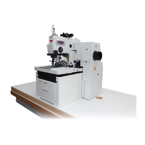
Eyelet buttonhole machine
Hide thumbs
Also See for REECE S-100:
- Parts and service manual (119 pages) ,
- Parts and service manual (90 pages)

Related Manuals for AMF REECE S-100


Summary of Contents for AMF REECE S-100
- Page 1 S-100 MODEL EYELET BUTTONHOLE MACHINE PARTS AND SERVICE MANUAL MACHINE SERIAL No. PART NUMBER 97. 1700.1.004 This manual is valid from the machine serial No.: J173961 02/ 2 0 0 6 AMF is trademark of AMF Group, Inc.
-
Page 2: Warranty Registration Card
Warranty Registration Card (Please Fax or Mail immediately after installation) Note: All Warranty Claims Void, unless Registration Card on file at AMF Reece HQ Machine model number: (S101, S100, S104, S211, Decostitch, S4000 BH, etc) Manufacturer‘s serial or production number: Installation Site Information: Customer‘s Name:... - Page 3 Authorized Distributor) will have the limited material warranty only. Only the defective material will be covered. Any charges associated with the use of an AMF Reece Technician or that of a Distributor to replace the defective part will be the customer’s responsibility.
-
Page 4: Table Of Contents
S100 TABLE OF CONTENTS A-INTRODUCTION 1. Introduction .......................... 1-1 2. Specifications ........................1-2 3. Safety of work ........................1-3 4. Security of the operator and maintenance ................1-4 5. List of the safety labels and devices ..................1-6 6. Position of the labels and the safety devices ................1-7 B - MACHINE INSTALLATION 1. - Page 5 1. Electrical diagrams ........................ 1-72 Revised 10/ 2005 e - mail service @amfreece.cz, parts @amf reece.cz,website: www.amfreece.com 1-10 Phones: + 420 582 309 146 ( service), + 420 582 309 286 (spare parts), Fax : + 420 582 360 606...
-
Page 6: A-Introduction
S100 A - INTRODUCTION 1 . I N T R O D U C T I O N The S100-030/031/032 (AF-CB/CA-RE) is a versatile two thread chain stitch sewing machine for sewing buttonholes with possibility to insert the gimp. The regular eye, Cut Before / Cut After, adjustable flybar machine may be used for suits, jeans and a wide variety of sewing applications. -
Page 7: Specifications
S100 A - INTRODUCTION 2 . S P E C I F I C AT I O N S Revised 10/2005 e-mail: service@amfreece.cz ; parts@amfreece.cz; website: www.amfreece.com Phones: +420 582 309 146 (Service), +420 582 309 286 (Spare Parts); Fax: +420 582 360 606... -
Page 8: Safety Of Work
Possible injury or machine damage. N O T I C E ! It is recommended to service workers from AMF Reece oversaw to the installation and initial training of mechanics and operators. Strictly given safety program, which part is the direction for safety operation, is the most effective security of the workers safety during the operating with the machine. -
Page 9: Security Of The Operator And Maintenance
S100 A - INTRODUCTION 4 . I N S T R U C T I O N S F O R T H E S E C U R I T Y O F T H E O P E R AT O R A N D M A I N T E N A N C E When the machine is set to the working area, it is recommended to keep the minimal distance said in the drawing. - Page 10 S100 A - INTRODUCTION Before changing the needle, switch off the operating switch (circuit breaker). In case when the operator will not work on the machine, disconnect the power supply by removing the plug from the socket. Before cleaning or any maintenance work on the machine, disconnect the power supply by removing the plug from the socket.
-
Page 11: List Of The Safety Labels And Devices
S100 A - INTRODUCTION 5 . L I S T O F T H E S A F E T Y L A B E L S A N D D E V I C E S 0.45 - 0.50 MPa Standard label. -
Page 12: Position Of The Labels And The Safety Devices
S100 A - INTRODUCTION 6 . P O S I T I O N O F T H E L A B E L S A N D T H E S A F E T Y D E V I C E S Machine head Locking screw... -
Page 13: B - Machine Installation
S100 B - MACHINE INSTALLATION Ê 1 . C O N T E N T O F T H E S H I P P I N G B O X 1. The delivery usually contains two boxes. One box contains the table and wiring, second the head of machine. -
Page 14: Machine Unpacking And Assembling
S100 B - MACHINE INSTALLATION 3 . M A C H I N E U N PA C K I N G A N D A S S E M B L I N G After unpacking it is necessary to put the table together according to the enclosed documentation. Delivered table is standardly took apart. - Page 15 S100 B - MACHINE INSTALLATION WA R N I N G ! It is commended to use original table, part number 04.90.17.0.xxx, for delivered machine. If the user has to use another table, producer can not take the responsibility for possible troubles. In this case it is necessary to use such equipment, which allows to reach on the left driving pulley for the machine cycle max.
- Page 16 S100 B - MACHINE INSTALLATION Fold the rear covers and tilt the head in the frame, make rear screws accessible during the assembly. Since some deliveries can have the covers partly dismantled, fix them to their place by using drawings in parts manual.
-
Page 17: Adjustment Of The T - Belt Tension For Sewing
S100 B - MACHINE INSTALLATION 4 . A D J U S T M E N T O F T H E T - B E LT T E N S I O N F O R S E W I N G The driving belt is placed under the right side cover. -
Page 18: Adjustment Of The Left T - Belt Tension
S100 B - MACHINE INSTLLATION 5 . A D J U S T M E N T O F T H E L E F T T- B E LT T E N S I O N The access to the belt will be obtained after folding of the folding rear cover. Then adjust the idler pulley until 13 mm, (1/2”) of flex is obtained in the belt, as illustrated. -
Page 19: Thread Stand Installation
S100 B - MACHINE INSTALLATION 6 . T H R E A D S TA N D I N S TA L L AT I O N Put the thread stand together according to the drawing. Position of the locking ring allows assembly of the thread stand for various thickness of the table top. -
Page 20: C - Operator Instructions
S100 C - OPERATOR INSTRUCTIONS 1 . P R E PA R I N G T O S E W Read through all safety instructions and ensure all covers are installed. Only Cord Trim - Check on the air pressure regulator that pressure is in range 4.5 - 5 bars (0.45 - 0.50 MPa), see note above the regulator. -
Page 21: Needle Installation
S100 C - OPERATOR INSTRUCTIONS 2 . N E E D L E I N S TA L L AT I O N Loosen needle locking screw and dismantle the original needle. Insert the new needle, so that the needle flat A is on opposite side from screw of the tension. - Page 22 S100 C - OPERATOR INSTRUCTIONS Threading the gimp and upper thread to the machine - S 100-030/031/032/033/035/036/052/053 To change the upper thread tension, use the nut Upper thread Gimp thread To adjust the gimp tension on the machine S 100 - 060 (CRB) use the screw Revised 10/2005 e-mail: service@amfreece.cz ;...
- Page 23 S100 C - OPERATOR INSTRUCTIONS L o w e r t h r e a d Use the manual nut to change the lower thread tension. Lower thread Revised 10/2005 e-mail: service@amfreece.cz ; parts@amfreece.cz; website: www.amfreece.com 1-18 Phones: +420 582 309 146 (Service), +420 582 309 286 (Spare Parts); Fax: +420 582 360 606...
-
Page 24: D - Machine Adjustments
S100 D - MACHINE ADJUSTMENT 1 . S T I T C H E S D E N S I T Y A D J U S T M E N T - S T R A I G H T S E C T I O N a ) m a c h i n e m o d i f i c a t i o n S 1 0 0 - 0 3 0 / 0 3 3 / 0 3 5 / 0 3 6 / 0 5 2 / 0 5 3 Remove auxiliary rear cover. - Page 25 S100 D - MACHINE ADJUSTMENT Wa r n i n g : When the machine is used for long time, the stitch density can be changed because of the running of the main cam brake and main shaft brake. That is why it is necessary to adjust the brakes. A d j u s t i n g m a i n c a m b r a k e The main cam brake controls the density of stitches which is adjust in chapter 2.
- Page 26 S100 D - MACHINE ADJUSTMENT A d j u s t m e n t o f t h e m a i n s h a f t b r a k e The main shaft brake equalizes the stitch density of the buttonhole seam for the left and right-hand sides.
-
Page 27: Adjustment Of The Stitches Density In The Eye
S100 D - MACHINE ADJUSTMENT 2 . A D J U S T M E N T O F T H E S T I T C H E S D E N S I T Y I N T H E E Y E This mechanism is not used for machine S 100 - 052 and S 100 - 053. -
Page 28: Lengths Of The Sewing
S100 D - MACHINE ADJUSTMENT 4 . L E N G T H S O F T H E S E W I N G The mechanism is not used for machine S 100 - 052 and S 100 - 053. Loosen the clamp screw and move with the rod till , so that the needed sewing length on the... -
Page 29: Change Of The Buttonhole Shape - Change Of The Lateral Cam
S100 D - MACHINE ADJUSTMENT 5. CHANGE OF THE BUTTONHOLE SHAPE - CHANGE OF THE LATERAL Machines S 100 - 0 3 0, S 100 - 0 3 1 and S 100 - 0 3 2 Fly bar Loosen the screw Lift the roll stud , so that the locking lever allows the insertion of new lateral cam... -
Page 30: Change Of The Width Bite
S100 D - MACHNE ADJUSTMENT Supplied lateral cams: Only for order: flybar 7 mm, stitch width 2 mm ** Only for CRB When the lateral cam is changed, it is necessary to ensure the adjustment of the WARNING ! correct buttonhole length, and install the correct cutting steel or knife. 6 . - Page 31 S100 D -MACHINE ADJUSTMENT Ï Î Î Ï Ï Î Revised 10/2005 e-mail: service@amfreece.cz ; parts@amfreece.cz; website: www.amfreece.com 1-26 Phones: +420 582 309 146 (Service), +420 582 309 286 (Spare Parts); Fax: +420 582 360 606...
- Page 32 S100 D - MACHINE ADJUSTMENT A d j u s t m e n t o f t h e w i d t h b i t e i n t h e c r o s s b a r The cross bar can be narrow down only by maximally 0.6 mm in adjusted width bite;.
-
Page 33: Principles Of Sewing
D - MACHINE ADJUSTMENT 7. P R I N C I P L E S O F S E W I N G S - 100 machine, produced by AMF Reece, sews two-thread, chain stitches with possibility to insert the gimp. - Page 34 S100 D - MACHINE ADJUSTMENT A stitch is the unit of thread formed in the production of seams and stitching. Stitching is defined as a series of stitches embodied in a material for ornamental purposes, for finishing an edge, or both. The type of stitch used in the eyelet buttonhole machine is a 401 stitch, two-thread, chain lock, purl stitch enveloping a reinforcing cord.
- Page 35 S100 D - MACHINE ADJUSTMENT The looper carrier continues moving to the right, carrying the lower thread, the left-hand looper, and the spreader, fully enter the formed loop. Needle Throat plate Upper thread Lower thread Gimp L.H. looper R.H. looper R.H.
- Page 36 S100 D - MACHINE ADJUSTMENT As the needle moves down to form a new loop, a take-up implement pulls the upper thread up into the material, and brings the lower thread with it. Needle Throat plate Upper thread Lower thread Gimp R.H.
- Page 37 S100 D - MACHINE ADJUSTMENT The looper carrier continues moving to the left. The right-hand looper and spreader fully enter the formed loop. Needle Throat plate Upper thread R.H. looper & spreader Lower thread Needle guard The right-hand spreader opens, making room for the needle to pass through a loop formed by the upper thread.
- Page 38 S100 D - MACHINE ADJUSTMENT The looper carrier moves to the right as the needle “strips” the loop previously formed. The left-hand looper enters the new loop which is being formed. Needle Upper thread Gimp Lower thread R.H. looper & spreader R.H.
-
Page 39: Bed Plate Alignment
S100 D - MACHINE ADJUSTMENT 8 . B E D P L AT E A L I G N M E N T Make the adjustment with the lateral cam for sewing of the buttonhole without eye and without flybar. Remove feet plates and instead of stitching plate install support of the gauge from accessories. -
Page 40: Turning Mechanism
S100 D - MACHINE ADJUSTMENT 1 0 . T U R N I N G M E C H A N I S M WA R N I N G ! This adjustment can be performed only by well trained mechanic. If the stitches are not vertical to the catted hole, it is necessary to adjust the turning mechanism: The machine must be in home position. - Page 41 S100 D - MACHINE ADJUSTMENT Space 1. row of 2. row of Table slot stitches stitches Gauge Space 2. row of stitches 1. row of stitches Give straight edge of the gauge over front edge of the supporting surface of the loopers. Check the space between the gauge and the table slat.
-
Page 42: Stopping Mechanism
S100 D - MACHINE ADJUSTMENT 11 . S T O P P I N G M E C H A N I S M WA R N I N G ! Switch off the main power to prevent accidental engagement of the machine. Rotate the handle until the machine is in the home position. - Page 43 S100 D - MACHINE ADJUSTMENT The clearance between the brake shaft and the cam of the hand wheel should be 0,05 - 0,10 mm, (0.002” - 0.004”). It can be adjust after loosing the screw of the three fork lever (below). Pull up the locking lever forward.
-
Page 44: Setting - Up The Mechanism For Fabric Clamping
S100 D - MACHINE ADJUSTMENT 12 . S E T T I N G - U P O F T H E M E C H A N I S M F O R FA B R I C C L A M P I N G Basic position of the feet plates with the feet is possible to adjust in position, when by turning the hand wheel the rollers are on the spreader block of the knife holder (picture, page 1-39) and feet plates are opened. -
Page 45: Clamp Plate Spreading
S100 D - MACHINE ADJUSTMENT 1 3 . C L A M P P L AT E S P R E A D I N G The amount of spread distance is determined by the sewing application. Loose fabric (especially thin) should cause stitches missing. -
Page 46: Length Setting - Up Of The Second Buttonhole Row
S100 D - MACHINE ADJUSTMENT 1 4 . L E N G T H S E T T I N G - U P O F T H E S E C O N D B U T T O N H O L E R O W Loosen the locking nut and rotate the adjustable screw for the correct last stitch stop location. -
Page 47: Needle Bar Height
S100 D - MACHINE ADJUSTMENT 1 6 . N E E D L E B A R H E I G H T Perform this adjustment when the machine is in the home position Remove the throat plate and the needle. Install the support of the gauge , instead of throat plate. - Page 48 After setting of the loopers is necessary to adjust center puncture to the buttonhole axis. Differently adjust the needle bar by the machines S-100.052/053, see MACHINE ADJUSTMENT ROUND BUTTON- HOLE - Differently position of the machine mechanisms S -100 - 052/053. The standard clearance be- tween the loopers and needle is 0.05 to 0.1 mm, (0.002 to 0.004").
-
Page 49: Spreaders Adjustment
S100 D - MACHINE ADJUSTMENT 1 8 . S P R E A D E R S A D J U S T M E N T Install left and right spreader , spreader stops and its springs Left fork spreader adjust above the hole in the left looper Inner side of right spreader adjust to the same level with appropriate inner side of the right looper It is possible to do adjustment after loosing the screws of the stop by its swinging. -
Page 50: Loopers Movement
S100 D - MACHINE ADJUSTMENT 1 9 . A D J U S T M E N T O F T H E L O O P E R S M O V E M E N T Turn the left handle of the machine until the drive shaft is released. Turn the right hand wheel until the needle bar is in the lower position of the center puncture. - Page 51 N o t e : Repeating the above mentioned steps is usual for reaching of the correct adjustment. C A U T I O N ! Using S 100 AMF Reece designed replacement parts, will ensure the best quality and highest production possible.
- Page 52 S100 D - MACHINE ADJUSTMENT Rotate the right-handwheel until the needle bar reaches the lowest point of the vibrator stroke. After raising the needle bar 3.5 mm, (0.140"), note the position of the right looper point to the center line of the needle.
-
Page 53: Setting - Up Of The Spreaders Movement
S100 D - MACHINE ADJUSTMENT 2 0 . S E T T I N G - U P O F T H E S P R E A D E R S M O V E M E N T It is necessary to adjust the spreaders so that the left and right spreader is opening and closing equally on the left and right, without contacting the needle. -
Page 54: Cutting Lever And Anvil
S100 D - MACHINE ADJUSTMENT 2 1 . C U T T I N G L E V E R A N D A N V I L Side adjustment of the cutting lever do with inserted knife after loosing the cutting lever studs locknuts and by moving the studs to the left or right, as needed. -
Page 55: Knife And Cutting Steel Change
S100 D - MACHINE ADJUSTMENT 2 2 . K N I F E A N D C U T T I N G S T E E L C H A N G E Various types of knives (straight buttonhole, cutting before and after sewing) and steels for machine S - 100 can be replaced. - Page 56 S100 D - MACHINE ADJUSTMENT Then position a piece of fabric between the knife and the cutting steel and cycle the machine and check the cut of the fabric. The cut must be even and can not be discontented through the whole length.
-
Page 57: Cutting Space Modification
S100 D - MACHINE ADJUSTMENT 2 3 . C U T T I N G S PA C E M O D I F I C AT I O N Change of the stitches rows position, increase or decrease the cutting space, it is used especially when the cutting before is changing to the cutting after. -
Page 58: Cut Before And Cut After
S100 D - MACHINE ADJUSTMENT 2 4 . C U T B E F O R E A N D C U T A F T E R Ensure the change by two functional components, after loosing the locking nut above and screw of the feet control lever down and by shifting in grooves in direction to the marked stops as needed, CA is... -
Page 59: Knife Adjustment For Upper Thread Trim
S100 D - MACHINE ADJUSTMENT 2 5 . K N I F E A D J U S T M E N T F O R U P P E R T H R E A D T R I M After repeatedly mounted holder with thread knife loosening the knife travel nut... - Page 60 S100 D - MACHINE ADJUSTMENT To adjust the actuator , loosen the actuator Picture 2 adjusting screw , then move the end position of the thread trimmer knife until the point of the knife passes the point of the right - hand looper, measured during the moment the actuator passes Screw over the pawl...
-
Page 61: Thread Draw Off Mechanism
S100 D - MACHINE ADJUSTMENT 2 6 . T H R E A D D R AW O F F M E C H A N I S M Basic position of the lever of the upper thread draw off is adjusted after loosing of the arresting screw Measure of the upper thread draw off is adjusted by means of stop screw... -
Page 62: Introduction
S100 E - MACHINE ADJUSTMENT FOR ROUND EYE 1 . I N T R O D U C T I O N The S 100 - 052 & -053 are two thread or single thread, round eye machines, used for decorative round holes in materials up to 6 mm thick, such as round holes in capes and cap vent holes. -
Page 63: Stop Motion Control
S100 E - MACHINE ADJUSTMENT FOR THE ROUND EYE 3 . S T O P M O T I O N C O N T R O L With the machine in the home position, using the adjustable screw , set the gap 0.1 to 0.2 mm, (0.004 to 0.008"). -
Page 64: Round Eye Machine Eyelet Diameter Or Cutting Space Change
S100 E - MACHINE ADJUSTMENT FOR THE ROUND EYE 4 . R O U N D E Y E M A C H I N E E Y E L E T D I A M E T E R O F C U T T I N G S PA C E C H A N G E To alter the eyelet diameter, without affecting the stitch bite, loosen the locking screw and rotate the... -
Page 65: Adjustment Of The Supplied Accessories
S100 E - MACHINE ADJUSTMENT FOR THE ROUND EYE 6 . A D J U S T M E N T O F T H E S U P P L I E D A C C E S S O R I E S This is used for machine rearrangement for one thread sewing. -
Page 66: F - Machine Adjustment - Cross Bar
S100 F - MACHINE ADJUSTMENT - CROSS BAR 1 . I N T R O D U C T I O N The S 100-060 are two threads or single thread machines with decorative chain stitch. Used for cross bar sewing buttonholes on the slacks, suits atc. -
Page 67: Device For Sewing The Cross Bar
S100 F - MACHINE ADJUSTMENT - CROSS BAR 4 . D E V I C E F O R S E W I N G T H E C R O S S B A R T h e m e c h a n i s m s f o r s e w i n g t h e c r o s s b a r a d j u s t m e n t Remove the side cover and tilt the rear cover. - Page 68 S100 F - MACHINE ADJUSTMENT - CROSS BAR Adjustment of the cam and the lever perform only after the buttonhole eye is adjusted - see chapter D 9. Use the hand crank turn the cam so that the pivot is still in the travel of the cam. This is the position, when the eye of the buttonhole was just sewn.
-
Page 69: Hand Feeding
S100 F -MACHINE ADJUSTMENT - CROSS BAR 5. R E A D J U S T M E N T O F T H E M A C H I N E S 1 0 0 - 0 6 0 ( C R O S S B A R ) T O T H E M A C H I N E S 1 0 0 - 0 3 0 ( W I T H O U T B A R ) Lift the pawl... -
Page 70: Cross Bar Length Adjustment
S100 F -MACHINE ADJUSTMENT - CROSS BAR If the hand crank feeding is used, make sure, that the stopping mechanism will not be open - lift the stopping lever If the cam reach to the loosen position, the cycle of sewing the cross bar must run (the cam mechanism must be turned by 360°... -
Page 71: Correction Of The Cross Bar Position In Axis X
S100 F -MACHINE ADJUSTMENT - CROSS BAR 9 . C O R R E C T I O N O F T H E CR O S S B A R P O S I T I O N I N A X I S X Stop the sewing in the position, when the stud leaves the before the second row of stitches is sewn, and lever... -
Page 72: Change Of The Machine Rotation
S100 F - MACHINE ADJUSTMENT - CROSS BAR 11 . C H A N G E O F T H E M A C H I N E R O TAT I O N It is necessary to decrease the sewing speed on the S 100 - 060 machine. The reason is cross bar sewing. The machine is supplied with the table, which allows 1450 rotations / min. -
Page 73: G - Machine Maintenance
S100 G - MACHINE MAINTENANCE WA R N I N G ! - Check the electrical cables for damage. - Check if the safety covers are in good condition. Replace damaged covers! - Keep your hands out from the needle space! - Do not modify the machine in any way, which can eliminate its safety parts. -
Page 74: Periodic Maintenance
S100 G - MACHINE MAINTENANCE 4. The air regulator maintenance - f o r m o d i f i c a t i o n C T ( S 1 0 0 - 0 3 3 / 0 3 5 / 0 3 6 ) o n l y . Maintenance of air regulator contains check of the condensate and possible replacement of the filter pad . -
Page 75: Machine Lubrication
S100 G - MACHIME MAINTENANCE 3 . M A C H I N E L U B R I C AT I O N It is necessary to lubricate the machine before the first switch on, or after long time, when the machine did not operate. -
Page 76: Machine Disposal
S100 G - MACHINE MAINTENANCE Auxiliary oil reservior 4. M A C H I N E D I S P O S A L To ensure machine ecological disposal it is necessary to remove especially nonmetallic parts from the machine. To take these parts out, it is necessary to perform the partial dismantling of the machine, remove covers, dismantle the machine arm and remove the frame. - Page 77 S100 H - DOCUMENTATION 1. E L E C T R I C A L W I R I N G D I A G R A M S WA R N I N G ! If the machine is not used with standard table, it is necessary to keep the connection, which correspond to safety precaution of the country, which is pursued in.
- Page 78 S100 H - DOCUMENTATION A S S E M B LY D I A G R A M Revised 10/2005 e-mail: service@amfreece.cz ; parts@amfreece.cz ; website: www.amfreece.com 1-73 Phones: +420 582 309 146 (Service), +420 582 309 286 (Spare Parts); Fax: +420 582 360 606...
- Page 79 S100 H - DOCUMENTATION Revised 10/2005 e-mail: service@amfreece.cz ; parts@amfreece.cz; website: www.amfreece.com 1-74 Phones: +420 582 309 146 (Service), +420 582 309 286 (Spare Parts); Fax: +420 582 360 606...
- Page 80 S100 H - DOCUMENTATION Revised 10/2005 e-mail: service@amfreece.cz ; parts@amfreece.cz ; website: www.amfreece.com 1-75 Phones: +420 582 309 146 (Service), +420 582 309 286 (Spare Parts); Fax: +420 582 360 606...
- Page 81 S100 H - DOCUMENTATION Revised 10/2005 e-mail: service@amfreece.cz ; parts@amfreece.cz; website: www.amfreece.com 1-76 Phones: +420 582 309 146 (Service), +420 582 309 286 (Spare Parts); Fax: +420 582 360 606...
- Page 82 S100 H - DOCUMENTATION Revised 10/2005 e-mail: service@amfreece.cz ; parts@amfreece.cz ; website: www.amfreece.com 1-77 Phones: +420 582 309 146 (Service), +420 582 309 286 (Spare Parts); Fax: +420 582 360 606...
- Page 83 S100 Revised 10/2005 e-mail: service@amfreece.cz ; parts@amfreece.cz; website: www.amfreece.com 1-78 Phones: +420 582 309 146 (Service), +420 582 309 286 (Spare Parts); Fax: +420 582 360 606...
- Page 84 S100 TABLE OF CONTENTS TROUBLESHOOTING Page Motor fails to start ....................2-2 The machine fails ..................... 2-2 Machine starts, but stops prematurely ............... 2-2 Machine starts, fails to stitch and stops ..............2-2 Machine fails to stitch, but completes the cycle ............2-2 Machine fails to stop stitching ...................
-
Page 85: Motor Fails To Start
S100 TROUBLESHOOTING SYMPTOMS POSSIBLE CHANGE PROBABLE SOLUTION PAGE No voltage. Check the main lead wire. Motor fails to start. Incorrect voltage. Perform voltmetr check. Check the main switch,the cutouts, Electrical equipment defect. and the emergency stop switch. Incorrect motor rotation. Change the plugs. -
Page 86: Machine Fails To Stop Stitching
S100 TROUBLESHOOTING SYMPTOM POSSIBLE CAUSE PROBABLE SOLUTION Incorrect stop mechanism function. Correctly adjust the pressure. Replace or correctly adjust the stop Machine fails to stop stitching. Worn or damaged stop mechnism teeth. mechanism teeth. Broken tension spring. Replace the spring. Cam braking belt tension too tight. -
Page 87: Uneven Clamp Feet Pressure
S100 TROUBLESHOOTING SYMPTOM POSSIBLE CAUSE PROBABLE SOLUTION Rocker lever bearing screw loose. Tighten the screw. Uneven clamp feet pressure. Tighten the screw or replace the drive Drive member loose or damaged. member. Damaged knife. Replace the knife. Damaged cutting block. Repair or replace the block. -
Page 88: Skipping Stitches
S100 TROUBLESHOOTING SYMPTOM POSSIBLE CAUSE PROBABLE SOLUTION Damaged or incorrectly installed Replace the needle. needle. Excessive looper to needle clearance. Correctly decrease the clearance. Correct the looper and the needle Incorrect looper and needle timing. timing. Correct the spreader open/close timing. Incorrect spreader open/close timing. -
Page 89: Bobbin Thread Break
S100 TROUBLESHOOTING SYMPTOM POSSIBLE CAUSE PROBABLE SOLUTION Excessive bobbin thread tension . Correctly decrease the tension. Incorrect left - hand spreader Correct the left - hand spreader installation. position. Needle contacts the looper. Correctly increase the clearance. Bobbin thread break. Needle contacts the clamp foot. -
Page 90: Incorrect Eye Shape
S100 TROUBLESHOOTING SYMPTOMS POSSIBLE CAUSE PROBABLE SOLUTION Improper lateral cam timing. Correctly adjust the cam timing. Correct the looper bracket initial Incorrect looper bracket initial position. position. Incorrect looper bracket turn angle. Correct the looper bracket turn angle. Incorrect eye shape. Incorrect knife drop position. -
Page 91: Round Eye Machines Only
S100 TROUBLESHOOTING ROUND EYE MACHINES ONLY : SYMPTOMS POSSIBLE CAUSE PROBABLE SOLUTION Correct the upper thread tension Incorrect upper thread tension release. release. Damaged right looper. Replace the looper. Removing stitches at the end of the sewing. Damaged throat plate hole. Replace the throat plate. - Page 92 S100 TROUBLESHOOTING THE CROSS BAR SEWING MACHINE S 1 0 0 - 0 6 0 SYMPTOMS POSSIBLE CAUSE PROBABLE SOLUTION The cross bar sewing is not Incorrect screw adjustment on the Adjust according to the chapter G3. vertical to the fly bar sewing. lever.
- Page 93 S100 TROUBLESHOOTING Revised 10/2005 2-10 e-mail: service@amfreece.cz, parts@amfreece.cz, website: www.amfreece.com Phones: +420 582 309 146 (service), +420 582 309 286 (spare parts), Fax + 420 582 360 606...
Need help?
Do you have a question about the REECE S-100 and is the answer not in the manual?
Questions and answers