Table of Contents
Advertisement
Quick Links
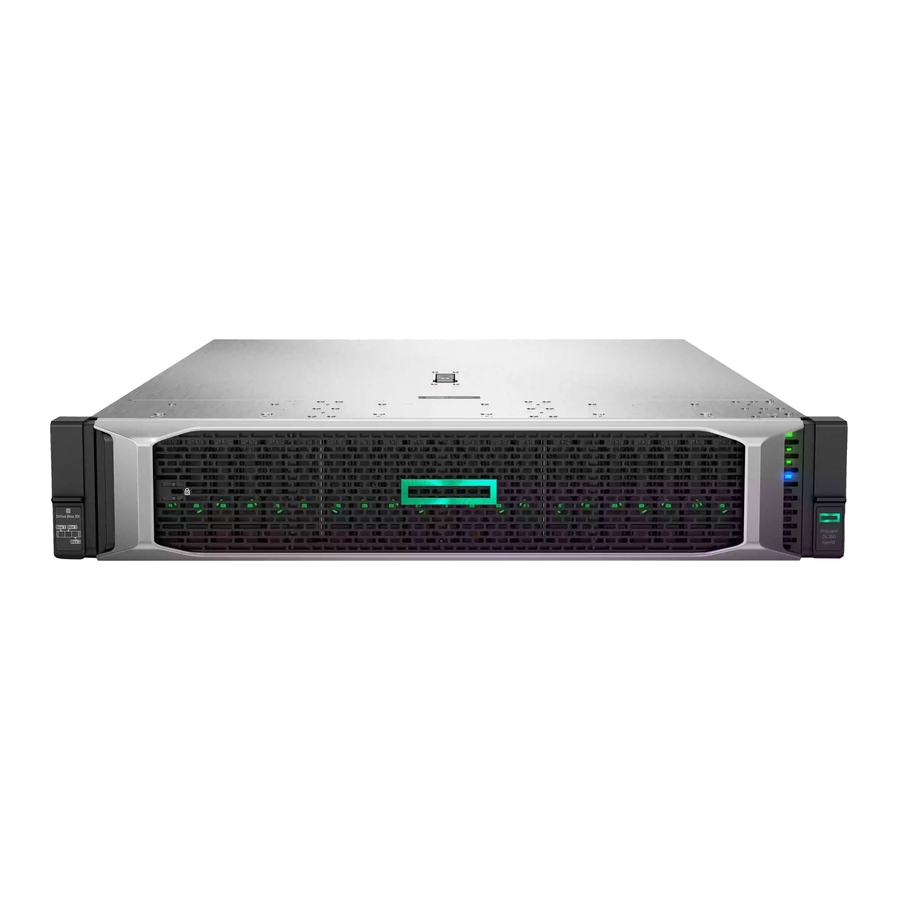
HPE ProLiant DL380 Gen10 Server User Guide
Abstract
This document is for the person who installs, administers, and troubleshoots servers and storage systems. Hewlett Packard
Enterprise assumes you are qualified in the servicing of computer equipment and trained in recognizing hazards in products
with hazardous energy levels.
Part Number: 868990-009a
Published: June 2020
Edition: 10
Advertisement
Table of Contents

Related Manuals for HPE ProLiant DL380 Gen10


Summary of Contents for HPE ProLiant DL380 Gen10
- Page 1 HPE ProLiant DL380 Gen10 Server User Guide Abstract This document is for the person who installs, administers, and troubleshoots servers and storage systems. Hewlett Packard Enterprise assumes you are qualified in the servicing of computer equipment and trained in recognizing hazards in products with hazardous energy levels.
- Page 2 © Copyright 2017-2020 Hewlett Packard Enterprise Development LP Notices The information contained herein is subject to change without notice. The only warranties for Hewlett Packard Enterprise products and services are set forth in the express warranty statements accompanying such products and services. Nothing herein should be construed as constituting an additional warranty.
-
Page 3: Table Of Contents
Drive bay numbering: NVMe drives................................36 uFF drive bay numbering....................................37 Riser components............................................38 HPE Flex Slot Power Supply with Integrated Battery Backup Unit components and LED............42 Checking the battery backup charge level............................. 42 HPE 12G SAS Expander Card port numbering..............................43 HPE Smart Array P824i-p MR Gen10 Controller..............................44 HPE InfiniBand HDR/Ethernet 940QSFP 56x16 adapter LEDs........................45... - Page 4 HPE 16GB NVDIMM option.....................................85 HPE Scalable Persistent Memory (CTO only)............................88 HPE Persistent Memory option..................................89 Controller options........................................... 92 Installing a storage controller..................................92 Installing an HPE Smart Array P824i-p MR Gen10 controller in a configured server..........93 Installing a Universal Media Bay.....................................96 Drive cage options..........................................98...
- Page 5 Installing a processor......................................... 148 HPE Trusted Platform Module 2.0 Gen10 option............................150 Overview..........................................150 HPE Trusted Platform Module 2.0 Guidelines..........................151 Installing and enabling the HPE TPM 2.0 Gen10 option......................151 Cabling..........................156 HPE ProLiant Gen10 DL Servers Storage Cabling Guidelines........................156 Cabling diagrams..........................................156 Cable routing: Front 2SFF drive option for SFF..........................159...
- Page 6 Environmental specifications......................................191 Mechanical specifications........................................191 Power supply specifications......................................192 HPE 500W Flex Slot Platinum Hot-plug Low Halogen Power Supply................192 HPE 800W Flex Slot Platinum Hot-plug Low Halogen Power Supply................193 HPE 800W Flex Slot Titanium Hot-plug Low Halogen Power Supply................194 HPE 800W Flex Slot Universal Hot-plug Low Halogen Power Supply................195 HPE 800W Flex Slot -48VDC Hot-plug Low Halogen Power Supply..................195...
- Page 7 Support and other resources....................199 Accessing Hewlett Packard Enterprise Support..............................199 Accessing updates..........................................199 Remote support.............................................200 Warranty information.........................................200 Regulatory information........................................200 Documentation feedback.........................................201...
-
Page 8: Component Identification
Component identification Front panel components SFF front panel components Item Description Box 1 (optional drives or universal media bay) Box 2 (optional drives) Box 3 Drives 1-8 Serial label pull tab or optional Systems Insight Display iLO service port USB 3.0 port Universal media bay components Item Description... - Page 9 12-drive LFF front panel components Item Description Drive bays 8-drive LFF model front panel components Item Description Drives (optional) LFF power switch module Drive bays LFF power switch module components Component identification...
-
Page 10: Front Panel Leds And Buttons
Item Description Optical disk drive Serial label pull tab USB 3.0 port iLO service port Video display port Front panel LEDs and buttons SFF front panel LEDs and button Item Description Status Power On/Standby button and Solid green = System on system power LED* Flashing green (1 Hz/cycle per sec) = Performing power on sequence... - Page 11 Item Description Status NIC status LED* Solid green = Link to network Flashing green (1 Hz/cycle per sec) = Network active Off = No network activity UID button/LED* Solid blue = Activated Flashing blue: • 1 Hz/cycle per sec = Remote management or firmware upgrade in progress •...
- Page 12 Item Description Status Health LED* Solid green = Normal Flashing green (1 Hz/cycle per sec) = iLO is rebooting Flashing amber = System degraded Flashing red (1 Hz/cycle per sec) = System critical** Power On/Standby button and Solid green = System on system power LED* Flashing green (1 Hz/cycle per sec) = Performing power on sequence...
- Page 13 LFF power switch module LEDs and button Item Description Status UID button/LED* Solid blue = Activated Flashing blue: • 1 Hz/cycle per sec = Remote management or firmware upgrade in progress • 4 Hz/cycle per sec = iLO manual reboot sequence initiated •...
-
Page 14: Uid Button Functionality
The UID button can be used to display the Server Health Summary when the server will not power on. For more information, see the latest HPE iLO 5 User Guide on the Hewlett Packard Enterprise website. Front panel LED power fault codes The following table provides a list of power fault codes, and the subsystems that are affected. - Page 15 Description Status Processor LEDs Off = Normal Amber = Failed processor DIMM LEDs Off = Normal Amber = Failed DIMM or configuration issue Fan LEDs Off = Normal Amber = Failed fan or missing fan NIC LEDs Off = No link to network Solid green = Network link Flashing green = Network link with activity If power is off, the front panel LED is not active.
-
Page 16: Systems Insight Display Combined Led Descriptions
Systems Insight Display combined LED descriptions The combined illumination of the following LEDs indicates a system condition: • Systems Insight Display LEDs • System power LED • Health LED Systems Insight Display LED Health LED System power Status and color Processor (amber) Amber One or more of the following conditions... -
Page 17: Rear Panel Components
Systems Insight Display LED Health LED System power Status and color Power supply (amber) Amber Green One or more of the following conditions might exist: • Redundant power supply is installed and only one power supply is functional. • AC power cord is not plugged into redundant power supply. -
Page 18: Rear Panel Leds
Item Description Serial port (optional)* 1Gb RJ-45 ports 1–4 (if equipped) iLO management port USB 3.0 ports FlexibleLOM slot *When a tertiary riser cage is installed as shown, the serial port can be installed in riser slot 6. Rear panel LEDs Item Description Status... -
Page 19: System Board Components
System board components Item Description FlexibleLOM connector System maintenance switch Primary PCIe riser connector Front display port/USB 2.0 connector Table Continued Component identification... -
Page 20: System Maintenance Switch Descriptions
Item Description x4 SATA port 1 x4 SATA port 2 x2 SATA port 3 x1 SATA port 4 Optical disk drive/SATA port 5 Power switch/SID module connector Drive backplane power connectors Energy pack connector Chassis intrusion detection connector Drive backplane power connector microSD card slot Dual internal USB 3.0 ports Type-a Smart Array connector... -
Page 21: Dimm Label Identification
Position Default Function — Reserved — Reserved — Reserved — Reserved — Reserved To access the redundant ROM, set S1, S5, and S6 to On. When the system maintenance switch position 6 is set to the On position, the system is prepared to restore all configuration settings to their manufacturing defaults. -
Page 22: Dimm Slot Locations
R = RDIMM (registered) L = LRDIMM (load reduced) E = Unbuffered ECC (UDIMM) For more information about product features, specifications, options, configurations, and compatibility, see the HPE DDR4 SmartMemory QuickSpecs on the Hewlett Packard Enterprise website (https://www.hpe.com/support/ DDR4SmartMemoryQS). DIMM slot locations DIMM slots are numbered sequentially (1 through 12) for each processor. -
Page 23: Nvdimm Identification
— For more information about NVDIMMs, see the product QuickSpecs on the Hewlett Packard Enterprise website (http:// www.hpe.com/info/qs). NVDIMM 2D Data Matrix barcode The 2D Data Matrix barcode is on the right side of the NVDIMM label and can be scanned by a cell phone or other device. -
Page 24: Nvdimm Led Identification
When scanned, the following information from the label can be copied to your cell phone or device: • (P) is the module part number. • (L) is the technical details shown on the label. • (S) is the module serial number. Example: (P)HMN82GR7AFR4N-VK (L)16GB 1Rx4 NN4-2666V-RZZZ-10(S)80AD-01-1742-11AED5C2 NVDIMM LED identification Item... -
Page 25: Hpe Persistent Memory Module Label Identification
The NVDIMM-N has an internal error or a firmware update is in Fast-flashing progress. For more information about an NVDIMM-N internal error, see the IML. HPE Persistent Memory module label identification Item Description Example Unique ID number 8089-A2-1802-1234567... -
Page 26: Processor, Heatsink, And Socket Components
For more information about product features, specifications, options, configurations, and compatibility, see the product QuickSpecs on the Hewlett Packard Enterprise website (https://www.hpe.com/support/persistentmemoryQS). Processor, heatsink, and socket components Item Description Heatsink nuts Processor carrier Pin 1 indicator Heatsink guide/keying feature Alignment post Heatsink keying frame Symbol also on the processor and frame. -
Page 27: Nvme Ssd Led Definitions
Item Description Status Locate • Solid blue = The drive is being identified by a host application. • Flashing blue = The drive carrier firmware is being updated or requires an update. Activity ring LED • Rotating green = Drive activity. •... - Page 28 Item Status Definition Locate Solid blue The drive is being identified by a host application. Flashing blue The drive carrier firmware is being updated or requires an update. Activity Rotating green Drive activity ring No drive activity Drive Solid green The drive is a member of one or more logical drives.
-
Page 29: Uff Drive Components And Leds
uFF drive components and LEDs Item Description Status Locate • Off—Normal • Solid blue—The drive is being identified by a host application • Flashing blue—The drive firmware is being updated or requires an update uFF drive ejection latch Removes the uFF drive when released Do not remove LED •... -
Page 30: Fan Bay Numbering
Fan bay numbering Drive box identification Front boxes Item Description Box 1 Box 2 Box 3 Component identification... - Page 31 Item Description Box 1 Box 2 Box 3 Rear boxes Item Description Box 4 Box 5 Box 6 Item Description Box 4 Box 6 Component identification...
-
Page 32: Drive Bay Numbering
Midplane box (LFF only) Item Description Box 7 Drive bay numbering Drive bay numbering depends on how the drive backplanes are connected: • To a controller ◦ Embedded controllers use the onboard SATA ports. ◦ Type-a controllers install to the type-a smart array connector. ◦... - Page 33 Component identification...
-
Page 34: Drive Bay Numbering: Sas Expander
Drive bay numbering: SAS expander Drive numbering through a SAS Expander is continuous. • SAS expander port 1 always connects to port 1 of the controller. • SAS expander port 2 always connects to port 2 of the controller. • SAS expander port 3 = drive numbers 1-4. - Page 35 When any stacked 2SFF drive configuration is connected to the SAS expander, the drive numbering skips the second number to allow uFF drive bay numbering. • Front 2SFF to SAS expander port 3: • Rear 2SFF to SAS expander port 9: •...
-
Page 36: Drive Bay Numbering: Nvme Drives
• Mid 4LFF to SAS expander port 6: • Front 12LFF + Midplane 4LFF + All rear 2SFF: Drive bay numbering: NVMe drives If the server is populated with NVMe drives and NVMe risers: Component identification... -
Page 37: Uff Drive Bay Numbering
uFF drive bay numbering There are two uFF drives in each drive carrier. If the drives are connected to a controller: • The left bay = The default bay number of the server • The right bay = The default bay number of the server + 100 If the drives are connected to a SAS expander: For example: •... -
Page 38: Riser Components
Riser components 4-port NVMe Slimline riser Item Description 1–4 x8 Slimline NVMe connectors Three-slot with NVMe Slimline riser Item Description x8 Slimline NVMe connector Controller backup power connectors (3) 3–5 x8 PCIe slots Component identification... - Page 39 Three-slot with M.2 riser Item Description GPU power cable connector Controller backup power connectors (3) M.2 SSD drive connectors x8 PCIe slot x16 PCIe slot x8 PCIe slot The riser supports installation of a second M.2 SSD drive on the reverse side. Three-slot GPU riser Item Description...
- Page 40 Two-slot GPU riser Item Description GPU power cable connector Controller backup power connectors (2) x16 PCIe slot x16 PCIe slot Two-slot x8 riser (tertiary) Item Description x8 PCIe slot x8 PCIe slot Controller backup power connectors (2) Component identification...
- Page 41 x8 riser (tertiary) Item Description x8 PCIe slot x8 Slimline NVMe connector Controller backup power connector Dual Slimline riser (tertiary) Item Description x8 Slimline NVMe connector x8 Slimline NVMe connector Component identification...
-
Page 42: Hpe Flex Slot Power Supply With Integrated Battery Backup Unit Components And Led
1. Battery check button 2. Power LED For more information about the HPE Flex Slot Power Supply with Integrated Battery Backup Unit, see the document that ships with the component. The label on the component indicates that the flex slot power supply has an integrated battery back up module. -
Page 43: Hpe 12G Sas Expander Card Port Numbering
30% <= RSOC <= 62% 63% <= RSOC <= 94% 95% <= RSOC Relative State of Charge The battery will fully charge within one hour of being installed into the server. HPE 12G SAS Expander Card port numbering Component identification... -
Page 44: Hpe Smart Array P824I-P Mr Gen10 Controller
HPE Smart Array P824i-p MR Gen10 Controller Components Item Description Internal SAS port 1i Internal SAS port 2i Internal SAS port 3i Internal SAS port 4i Controller backup power cable connector Internal SAS port 5i Internal SAS port 6i Component identification... -
Page 45: Hpe Infiniband Hdr/Ethernet 940Qsfp 56X16 Adapter Leds
HPE InfiniBand HDR/Ethernet 940QSFP 56x16 adapter LEDs Link LED status Description A link has not been established. Solid amber Active physical link exists Blinking amber 4 Hz blinking amber indicates a problem with the physical link. Solid green A valid logical (data activity) link exists with no active traffic. - Page 46 LEDs The HPE for Pensando DSP DSC-25 2p SFP28 Card is a dual-port, single-slot, half-height, half-length (HHHL) SFP28 network adapter. It has LEDs for Link (L) and Activity (A) for each port. A half-height bracket is shown in the following illustration with SFP28 ports and LEDs.
- Page 47 Item Status Description Flashing green Passing traffic; flashing frequency indicates traffic intensity Solid amber Link fault System status LED System is not powered Solid amber Power is up, software has not booted yet Solid green System is up and fully operational Component identification...
-
Page 48: Operations
Operations Power up the server To power up the server, use one of the following methods: • Press the Power On/Standby button. • Use the virtual power button through iLO. Power down the server Before powering down the server for any upgrade or maintenance procedures, perform a backup of critical server data and programs. -
Page 49: Removing The Server From The Rack
Removing the server from the rack To remove the server from a Hewlett Packard Enterprise, Compaq-branded, Telco, or third-party rack: Procedure 1. Power down the server. 2. Extend the server from the rack. 3. Disconnect the cabling and remove the server from the rack. For more information, see the documentation that ships with the rack mounting option. -
Page 50: Release The Cable Management Arm
To identify components, see Rear panel components. 2. At the rear of the server, plug in the power cord to the power supply. 3. Install the power cord anchors. 4. Secure the cables to the cable management arm. IMPORTANT: Leave enough slack in each of the cables to prevent damage to the cables when the server is extended from the rack. -
Page 51: Remove The Access Panel
Remove the access panel WARNING: To reduce the risk of personal injury from hot surfaces, allow the drives, power supplies, and internal system components to cool before touching them. CAUTION: Do not operate the chassis for long periods with the access panel open or removed. Operating the chassis in this manner results in improper airflow and improper cooling that can lead to thermal damage. -
Page 52: Removing The Fan Cage
Removing the fan cage CAUTION: Do not operate the server for long periods with the access panel open or removed. Operating the server in this manner results in improper airflow and improper cooling that can lead to thermal damage. IMPORTANT: For optimum cooling, install fans in all primary fan locations. Procedure 1. -
Page 53: Removing The Air Baffle Or Midplane Drive Cage
IMPORTANT: For optimum cooling, install fans in all primary fan locations. Removing the air baffle or midplane drive cage CAUTION: Do not detach the cable that connects the battery pack to the cache module. Detaching the cable causes any unsaved data in the cache module to be lost. CAUTION: For proper cooling, do not operate the server without the access panel, baffles, expansion slot covers, or blanks installed. - Page 54 • Remove the 4LFF midplane drive cage: a. Disconnect all cables. b. Remove all drives. Be sure to note the location of each drive. c. Remove the drive cage. CAUTION: Do not drop the drive cage on the system board. Dropping the drive cage on the system board might damage the system or components.
-
Page 55: Installing The Air Baffle
Installing the air baffle Procedure 1. Observe the following alerts. CAUTION: For proper cooling, do not operate the server without the access panel, baffles, expansion slot covers, or blanks installed. If the server supports hot-plug components, minimize the amount of time the access panel is open. CAUTION: Do not detach the cable that connects the battery pack to the cache module. -
Page 56: Removing A Riser Slot Blank
• Extend the server from the rack. • Remove the server from the rack. 4. Remove the access panel. 5. Remove the riser cage: • Primary and secondary riser cages • Tertiary riser cage Removing a riser slot blank CAUTION: To prevent improper cooling and thermal damage, do not operate the server unless all PCI slots have either an expansion slot cover or an expansion board installed. -
Page 57: Removing The Hard Drive Blank
Procedure 1. Power down the server. 2. Remove all power: a. Disconnect each power cord from the power source. b. Disconnect each power cord from the server. 3. Do one of the following: • Extend the server from the rack. •... - Page 58 Operations...
-
Page 59: Setup
HPE support services offer upgraded service levels to expand the standard product warranty with easy-to-buy, easy-to-use support packages that will help you make the most of your server investments. Some of the HPE support services for hardware, software or both are: •... - Page 60 ◦ Download it from the HPE support center website. ◦ Extract it from the SPP. Procedure Unbox the server 1. Unbox the server and verify the contents: • A server • A power cord • Rack-mounting hardware • Documentation 2. (Optional) Install hardware options.
- Page 61 If a smart array controller is installed: ◦ For smart array SR controllers, use HPE Smart Storage Administrator to create arrays: a. From the boot screen, press F10 to run Intelligent Provisioning. b. From Intelligent Provisioning, run HPE Smart Storage Administrator.
-
Page 62: Operational Requirements
From the boot screen, press F9 to run UEFI System Utilities. From the UEFI System Utilities screen, select System Configuration > Embedded Storage: HPE Smart Storage S100i SR Gen10 > Array Configuration > Create Array Deploy an OS or virtualization software 8. - Page 63 CAUTION: When using a Compaq branded 7000 series rack, install the high airflow rack door insert (PN 327281-B21 for 42U rack, PN 157847-B21 for 22U rack) to provide proper front-to-back airflow and cooling. CAUTION: If a third-party rack is used, observe the following additional requirements to ensure adequate airflow and to prevent damage to the equipment: •...
- Page 64 Because of the high ground-leakage currents associated with multiple servers connected to the same power source, Hewlett Packard Enterprise recommends the use of a PDU that is either permanently wired to the building’s branch circuit or includes a nondetachable cord that is wired to an industrial-style plug. NEMA locking-style plugs or those complying with IEC 60309 are considered suitable for this purpose.
-
Page 65: Server Warnings And Cautions
IMPORTANT: The minimum nominal thread diameter of a pillar or stud type terminal must be 3.5 mm (0.138 in); the diameter of a screw type terminal must be 4.0 mm (0.157 in). 3. Stack each same-colored pair of wires and then attach them to the same power source. The power cord consists of three wires (black, red, and green). -
Page 66: Rack Warnings
Rack warnings WARNING: To reduce the risk of personal injury or damage to the equipment, be sure that: • The leveling jacks are extended to the floor. • The full weight of the rack rests on the leveling jacks. • The stabilizing feet are attached to the rack if it is a single-rack installation. -
Page 67: Server Box Contents
Before installing an operating system, observe the following: • Be sure to read the HPE UEFI requirements for ProLiant servers on the Hewlett Packard Enterprise website. If UEFI requirements are not met, you might experience boot failures or other errors when installing the operating system. -
Page 68: Registering The Server
Registering the server To experience quicker service and more efficient support, register the product at the Hewlett Packard Enterprise Product Registration website. Setup... -
Page 69: Hardware Options Installation
Product QuickSpecs For more information about product features, specifications, options, configurations, and compatibility, see the product QuickSpecs on the Hewlett Packard Enterprise website (https://www.hpe.com/info/qs). Introduction Install any hardware options before initializing the server. If multiple options are being installed, read the installation instructions for all the hardware options to identify similar steps and streamline the installation process. -
Page 70: Installing The Bezel And Bezel Lock
Hot-plug power supply calculations For hot-plug power supply specifications and calculators to determine electrical and heat loading for the server, see the Hewlett Packard Enterprise Power Advisor website (https://www.hpe.com/info/poweradvisor/online). Installing a redundant hot-plug power supply CAUTION: All power supplies installed in the server must have the same output power capacity. Verify that all power supplies have the same part number and label color. - Page 71 CAUTION: To prevent improper cooling and thermal damage, do not operate the server unless all bays are populated with either a component or a blank. Procedure 1. Release the cable management arm to access the rear panel. 2. Remove the blank. WARNING: To reduce the risk of personal injury from hot surfaces, allow the power supply or power supply blank to cool before touching it.
-
Page 72: Energy Pack Options
One energy pack option can support multiple devices. An energy pack option is required for P-class Smart Array controllers. Once installed, the status of the energy pack displays in HPE iLO. For more information, see the HPE iLO user guide on the Hewlett Packard Enterprise website (https://www.hpe.com/support/ilo-docs). - Page 73 • Extend the server from the rack. • Remove the server from the rack. Remove the access panel. Do one of the following: • Remove the air baffle. • If installed on LFF models, remove the midplane drive cage. Install the Smart Storage battery. Install the cable.
-
Page 74: Hpe Smart Storage Hybrid Capacitor
The capacitor pack can support up to three devices. This server supports the HPE Smart Storage Hybrid Capacitor with the 145mm cable. Before installing the HPE Smart Storage Hybrid Capacitor, verify that the system BIOS meets the minimum firmware requirements to support the capacitor pack. - Page 75 Procedure Power down the server. Remove all power: a. Disconnect each power cord from the power source. b. Disconnect each power cord from the server. Do one of the following: • Extend the server from the rack. • Remove the server from the rack. Remove the access panel.
-
Page 76: Drive Options
Install the fan cage. 10. Install the access panel. 11. Install the server into the rack. 12. Connect each power cord to the server. 13. Connect each power cord to the power source. 14. Power up the server. Drive options Drive guidelines Depending on the configuration, the server supports SAS, SATA, and NVMe drives. -
Page 77: Installing A Hot-Plug Sas Or Sata Drive
• SFF Smart Carrier (SC) • SFF Smart Carrier NVMe (SCN) • SFF Smart Carrier M.2 (SCM) • LFF Smart Carrier (SC) • LFF to SFF Smart Carrier Converter Installing a hot-plug SAS or SATA drive Procedure 1. Remove the drive blank. 2. -
Page 78: Installing An Nvme Drive
Installing a uFF drive and SCM drive carrier IMPORTANT: Not all drive bays support the drive carrier. To find supported bays, see the server QuickSpecs on the Hewlett Packard Enterprise website (https://www.hpe.com/info/qs). Procedure 1. If needed, install the uFF drive into the drive carrier. -
Page 79: Installing An M.2 Drive
Push firmly near the ejection handle until the latching spring engages with the drive bay. 4. Power on the server. To configure the drive, use HPE Smart Storage Administrator. Installing an M.2 drive This procedure is for replacing M.2 drives located on an expansion card, riser, or the system board only. Do not use this procedure to replace uFF drives. -
Page 80: Fan Options
Procedure 1. Power down the server. 2. Remove all power: a. Disconnect each power cord from the power source. b. Disconnect each power cord from the server. 3. Do one of the following: • Extend the server from the rack. •... -
Page 81: Installing High-Performance Fans
Configuration Fan bay 1 Fan bay 2 Fan bay 3 Fan bay 4 Fan bay 5 Fan bay 6 1 processor Fan blank Fan blank 1 processor 24-SFF or 12-LFF configuration with high-performance fans 2 processors For a single-processor configuration, excluding 24-SFF and 12-LFF configurations, four fans and two blanks are required in specific fan bays for redundancy. - Page 82 4. Remove the air baffle. 5. Remove all standard fans. IMPORTANT: Do not mix standard fans and high-performance fans in the same server. 6. Install high-performance fans in all fan bays. Hardware options installation...
-
Page 83: Memory Options
For specific DIMM and NVDIMM population information, see the DIMM population guidelines on the Hewlett Packard Enterprise website (http://www.hpe.com/docs/memory-population-rules). HPE SmartMemory speed information For more information about memory speed information, see the Hewlett Packard Enterprise website (https://www.hpe.com/ docs/memory-speed-table). Installing a DIMM The server supports up to 24 DIMMs. - Page 84 Prerequisites Before installing this option, be sure you have the following: The components included with the hardware option kit For more information on specific options, see the server QuickSpecs on the Hewlett Packard Enterprise website. Procedure Power down the server. Remove all power: a.
-
Page 85: Hpe 16Gb Nvdimm Option
The server can support up to 12 NVDIMMs in 2 socket servers (up to 192GB) and up to 24 NVDIMMs in 4 socket servers (up to 384GB). The HPE Smart Storage Battery provides backup power to the memory slots allowing data to be moved from the DRAM portion of the NVDIMM to the Flash portion for persistence during a power down event. - Page 86 HPE Smart Storage Battery, fails. HPE Smart Storage battery is a critical component required to perform the backup functionality of NVDIMMs. It is important to act when HPE Smart Storage Battery related failures occur. Always follow best practices for ensuring data protection.
- Page 87 F9 key during POST. For more information about UEFI System Utilities, see the Hewlett Packard Enterprise website (http://www.hpe.com/info/uefi/docs). iLO RESTful API for HPE iLO 5—For more information about configuring the system for NVDIMMs, see https:// •...
-
Page 88: Hpe Scalable Persistent Memory (Cto Only)
The NVDIMM-N Sanitize options are intended to meet the Purge level. For more information on sanitization for NVDIMMs, see the following sections in the HPE 16GB NVDIMM User Guide on the Hewlett Packard Enterprise website (http://www.hpe.com/info/nvdimm-docs): • NVDIMM sanitization policies •... -
Page 89: Hpe Persistent Memory Option
HPE Persistent Memory option HPE Persistent Memory, which offers the flexibility to deploy as dense memory or fast storage and features Intel Optane persistent memory, enables per-socket memory capacity of up to 3.0 TB. HPE Persistent Memory, together with traditional volatile DRAM DIMMs, provide fast, high-capacity, cost-effective memory and storage to transform big data workloads and analytics by enabling data to be stored, moved, and processed quickly. - Page 90 Installing an HPE Persistent Memory module Use this procedure only for new HPE Persistent Memory module installations. If you are migrating this HPE Persistent Memory module from another server, see the HPE Persistent Memory User Guide on the Hewlett Packard Enterprise website (https:// www.hpe.com/info/persistentmemory-docs).
- Page 91 DIMM or HPE Persistent Memory module with the corresponding notches in the slot before installing the component. Do not force the DIMM or HPE Persistent Memory module into the slot. When installed properly, not all DIMMs or HPE Persistent Memory modules will face in the same direction.
-
Page 92: Controller Options
• HPE Persistent Memory Management Utility—The HPE Persistent Memory Management Utility is a desktop application used to configure the server for HPE Persistent Memory, as well as evaluate and monitor the server memory configuration layout. For more information, see the HPE Persistent Memory User Guide on the Hewlett Packard Enterprise website (https:// www.hpe.com/info/persistentmemory-docs). -
Page 93: Installing An Hpe Smart Array P824I-P Mr Gen10 Controller In A Configured Server
For Type-p Smart Array controllers, install the controller in a compatible expansion slot. • 7. Cable the controller. The installation is complete. Installing an HPE Smart Array P824i-p MR Gen10 controller in a configured server Procedure Back up data on the system. Close all applications. - Page 94 • If the new Smart Array is the new boot device, install the device drivers. • If the new Smart Array is not the new boot device, go to the next step. NOTE: If the logical drive is used in a Smart Array SR controller RAID array, you are not able to boot from that device if you are attached to a Smart Array MR controller.
- Page 95 • HPE MR Storage Administrator • StorCLI HPE MR Storage Administrator and StorCLI are available in the Service Pack for Proliant (SPP). For more information about using each configuration utility, see the documentation for the configuration utility. Hardware options installation...
-
Page 96: Installing A Universal Media Bay
NOTE: • Any RAID configuration created for the HPE Smart Array MR controller is not available to HPE Smart Array SR controllers. • The message "Data Protection disabled" in the logical drive properties can be ignored as it refers to a feature not currently supported by the HPE MR Storage Administrator product. - Page 97 Route the USB and video cables through the opening. If installing a two-bay SFF front drive cage, install the drive cage. 10. Install the universal media bay. 11. (Optional) Install the optical disc drive. Hardware options installation...
-
Page 98: Drive Cage Options
12. Connect the cables. 13. Install the fan cage. 14. Install the air baffle. 15. Install the access panel. 16. Slide the server into the rack. 17. Connect each power cord to the server. 18. Connect each power cord to the power source. 19. - Page 99 WARNING: To reduce the risk of personal injury from hot surfaces, allow the drives and the internal system components to cool before touching them. CAUTION: To prevent damage to electrical components, properly ground the server before beginning any installation procedure. Improper grounding can cause ESD. Power down the server.
-
Page 100: Installing A Front 6Sff Sas/Sata + 2Nvme Premium Drive Cage
Install the associated NVMe riser. 10. Connect the power cable to the drive backplane power connector. 11. Connect the data cables from the drive backplane to the NVMe riser. 12. Install drives or drive blanks. The installation is complete. Installing a front 6SFF SAS/SATA + 2NVMe Premium drive cage The drive cage can be installed in any box. - Page 101 Remove the fan cage. Remove the blank. Install the drive cage: a. If drive blanks are installed in the drive cage assembly, remove the drive blanks. Retain the drive blanks for use in empty drive bays. b. Install the drive cage. Connect the power cable.
- Page 102 Installing airflow labels When an Express Bay drive cage is installed, airflow labels might be required: Prerequisites Before you perform this procedure, make sure that you have the components included with the hardware option kit. Procedure • If an eight-bay SFF drive cage is installed in box 1, then airflow labels are not required. •...
-
Page 103: Installing A Front 8Sff Sas/Sata Drive Cage In Box 1
Installing a front 8SFF SAS/SATA drive cage in box 1 Prerequisites Before you perform this procedure, make sure that you have the following items available: • T-10 Torx screwdriver • The components included with the hardware option kit Procedure Power down the server. Remove all power: a. - Page 104 Install the 8SFF front drive cage option. Connect the power and data cables. 10. Install the fan cage. 11. Install the air baffle. 12. Install the access panel. 13. Slide the server into the rack. 14. Connect each power cord to the server. 15.
-
Page 105: Installing A Front 8Sff Sas/Sata Drive Cage In Box 2
Installing a front 8SFF SAS/SATA drive cage in box 2 Procedure Power down the server. Remove all power: a. Disconnect each power cord from the power source. b. Disconnect each power cord from the server. Do one of the following: Extend the server from the rack. -
Page 106: Installing A Front 2Sff Nvme/Sas/Sata Premium Drive Cage
Connect the power and data cables. 10. Install the fan cage. 11. Install the access panel. 12. Slide the server into the rack. 13. Connect each power cord to the server. 14. Connect each power cord to the power source. 15. - Page 107 • Extend the server from the rack. • Remove the server from the rack. Remove the access panel. Remove the front bay blank. Remove the optical disc drive from the universal media bay. Remove the SFF drive blank from the universal media bay. Hardware options installation...
- Page 108 Install the drive cage into the universal media bay. Install the optical disc drive in the universal media bay. Hardware options installation...
-
Page 109: Installing A Midplane 4Lff Sas/Sata Drive Cage
10. Install the universal media bay. 11. Connect the power and data cables. 12. Install the access panel. 13. Slide the server into the rack. 14. Connect each power cord to the server. 15. Connect each power cord to the power source. 16. - Page 110 • A 1U heatsink is required for each processor when installing this option. • If you have a TPM, install it prior to this option. • If you have a type-a controller, install it prior to this option. Prerequisites Before you perform this procedure, make sure that you have the following items available: The components included with the hardware option kit Procedure Power down the server.
- Page 111 Connect the power cable to the drive backplane power connector on the system board. If connecting the data cable to the system board or a controller, connect the data cable. Prepare the drive cage for installation by lifting the latches on the drive cage. 10.
-
Page 112: Installing A Rear 2Sff Sas/Sata Drive Cage In The Primary Or Secondary Riser
11. Install drives or drive blanks. 12. Push down on the latches to lower the drive cage into place. 13. Connect the power and data cables to the drive backplane. The installation is complete. Installing a rear 2SFF SAS/SATA drive cage in the primary or secondary riser Prerequisites Before you perform this procedure, make sure that you have the following items available: •... - Page 113 Do one of the following: For primary bays, remove the riser cage. For secondary bays, remove the rear wall blank. Install a SAS expander or other expansion card, if needed. Install the drive cage. Hardware options installation...
-
Page 114: Installing A Rear 2 Sff Sas/Sata Drive Cage Over The Power Supplies
Cable the drive backplane. Install drives or drive blanks. 10. Install the access panel. 11. Slide the server into the rack. 12. Connect each power cord to the server. 13. Connect each power cord to the power source. 14. Power up the server. The installation is complete. - Page 115 • Extend the server from the rack. • Remove the server from the rack. Remove the access panel. Do one of the following: • If installed, remove the secondary riser cage. • Remove the secondary wall blank. Remove the tertiary wall blank. Hardware options installation...
- Page 116 Install the drive cage compatible rear wall. Install the drive cage. Hardware options installation...
-
Page 117: Installing A Rear 3Lff Sas/Sata Drive Cage
Install drives or drive blanks. 10. Install the secondary riser cage or rear wall. 11. Cable the drive backplane. 12. Install the access panel. 13. Slide the server into the rack. 14. Connect each power cord to the server. 15. Connect each power cord to the power source. 16. - Page 118 Do one of the following: • Extend the server from the rack. Remove the server from the rack. • Remove the access panel. If installed, remove the secondary riser cage. The secondary riser cage is not supported with a three-bay LFF rear configuration.
-
Page 119: Riser And Riser Cage Options
Install drives or drive blanks. Connect the power and data cables. 10. Install the access panel. 11. Slide the server into the rack. 12. Connect each power cord to the server. 13. Connect each power cord to the power source. 14. - Page 120 Do one of the following: • Extend the server from the rack. Remove the server from the rack. • Remove the access panel. Remove the riser cage. Remove the riser board. Install the riser. If needed, install an expansion board. If needed, connect data cables to the riser or expansion board.
-
Page 121: Installing Tertiary Risers
Installing tertiary risers Prerequisites Before you perform this procedure, make sure that you have the following items available: • The components included with the hardware option kit • T-10 Torx screwdriver • A tertiary riser cage is required to install this option. Procedure Power down the server. -
Page 122: Installing A Secondary Riser Cage
Installing a secondary riser cage Prerequisites Before you perform this procedure, make sure that you have the following items available: • The components included with the hardware option kit • T-10 Torx screwdriver Procedure 1. Observe the following alert: CAUTION: To prevent damage to the server or expansion boards, power down the server and remove all AC power cords before removing or installing the PCI riser cage. -
Page 123: Installing A Tertiary Riser Cage
The installation is complete. Installing a tertiary riser cage Prerequisites Before you perform this procedure, make sure that you have the following items available: • The components included with the hardware option kit • T-10 Torx screwdriver Procedure 1. Observe the following alert. CAUTION: To prevent damage to the server or expansion boards, power down the server and remove all AC power cords before removing or installing the PCI riser cage. - Page 124 7. Install the rear blank from the option kit. Hardware options installation...
-
Page 125: Installing The 2Nvme Slimsas Riser Option
8. Install any expansion boards, if needed 9. Install the tertiary riser cage: The installation is complete. Installing the 2NVMe slimSAS riser option Prerequisites Before you perform this procedure, make sure that you have the following items available: • The components included with the hardware option kit •... -
Page 126: Installing The 8Nvme Slimsas Riser Option
Procedure 1. Power down the server. 2. Do one of the following: • Disconnect each power cord from the power source. • Disconnect each power cord from the server. 3. Do one of the following: • Extend the server from the rack. Remove the server from the rack. -
Page 127: Expansion Slots
To install the riser in the primary position: To install the riser in the secondary position, install the secondary riser cage. 7. Connect data cables to the drive backplane. Expansion slots Supported PCIe form factors All slots support full-height expansion cards. Use the following information to find supported lengths for each slot. Slot description example Hardware options installation... -
Page 128: Installing Expansion Boards
Primary riser connector PCIe slot and card length 3-slot riser* 2-slot riser (Optional) 2-slot riser (Optional) Slot 1 - Full-length/Full- PCIe3 x8 (8, 4, 2, 1) — PCIe3 x16 (16, 8, 4, 2, 1) height (FL/FH) Slot 2 - Full-length/Full- PCIe3 x16 (16, 8, 4, 2, 1) PCIe3 x16 (16, 8, 4, 2, 1) PCIe3 x16 (16, 8, 4, 2, 1) - Page 129 Procedure Power down the server. Remove all power: a. Disconnect each power cord from the power source. b. Disconnect each power cord from the server. Do one of the following: • Extend the server from the rack. • Remove the server from the rack. Remove the access panel.
-
Page 130: Installing A 12G Sas Expander Card
For 24SFF configurations, install 8SFF front drive cages in boxes 1 and 2. • For configurations including a 2SFF rear drive cage, install the drive cage over the power supplies. • HPE recommends installing the SAS expander card into slot 3 of the primary PCIe riser expansion card. Hardware options installation... - Page 131 • To ensure that cables are connected correctly, observe the labels on the cable and port. • Be sure that you have the latest firmware for the controllers and the expander card. To download the latest firmware, see the Hewlett Packard Enterprise website. Prerequisites Before you perform this procedure, make sure that you have the following items available: •...
- Page 132 Install the 12G SAS expander card. IMPORTANT: The 12G SAS expander card requires a controller. The server supports embedded, type-a, and type- p Smart Array controllers. If using a type-p Smart Array controller, then install the controller in slot 1. 10.
-
Page 133: Installing An Accelerator Or Gpu
16. Install the access panel. 17. Install the server into the rack. 18. Connect each power cord to the server. 19. Connect each power cord to the power source. 20. Power up the server . The installation is complete. Installing an accelerator or GPU An accelerator or GPU can be installed into the primary, secondary, or tertiary position. - Page 134 b. Install the appropriate retention clip onto the air baffle. Install the clip that supports your configuration. Primary, secondary, and tertiary positions are shown. Install high-performance heatsinks. Install the air baffle. 10. Remove the rear wall blank. The secondary rear wall blank is shown. Hardware options installation...
- Page 135 To install a card in the primary riser cage, see "Removing a riser cage". To install a card in the tertiary riser cage, see "Installing a tertiary riser cage". 11. Remove the PCIe blank. 12. Install the card into the riser. Hardware options installation...
- Page 136 13. If required, connect the power cable from the card to the riser. 14. For full-length cards, open the retention clips. 15. Install the riser cage. Hardware options installation...
-
Page 137: Installing The Chassis Intrusion Detection Switch
16. For full-length cards, slide the retention clips to the locked position. The installation is complete. Installing the chassis intrusion detection switch Prerequisites Before you perform this procedure, make sure that you have the following items available: The components included with the hardware option kit Procedure Power down the server. -
Page 138: Installing A Rear Serial Port Interface
a. Disconnect each power cord from the power source. b. Disconnect each power cord from the server. Do one of the following: Extend the server from the rack. • • Remove the server from the rack. Remove the access panel. Install the chassis intrusion detection switch. - Page 139 Procedure Power down the server. Do one of the following: • Disconnect each power cord from the power source. • Disconnect each power cord from the server. Do one of the following: • Extend the server from the rack. Remove the server from the rack. •...
- Page 140 If a tertiary riser cage is installed, perform the following steps: a. Remove the riser and the blank. b. Install the serial port. Hardware options installation...
-
Page 141: Installing The Systems Insight Display
Install the access panel. Install the server in the rack. Connect each power cord to the server. 10. Connect each power cord to the power source. 11. Power up the server. The installation is complete. Installing the Systems Insight Display Prerequisites Before you perform this procedure, make sure that you have the following items available: •... - Page 142 • Extend the server from the rack. • Remove the server from the rack. Remove the access panel. Do one of the following: • Remove the air baffle. • If installed, remove the 4LFF midplane drive cage. Remove the fan cage. Disconnect the power switch module cable from the power switch/SID module connector.
-
Page 143: Installing A Flexiblelom Adapter
10. Connect the SID module cable to the power switch/SID module connector. 11. Install the fan cage. 12. Do one of the following: • Install the air baffle. • Perform steps 9–13 of “Installing a midplane 4LFF SAS/SATA drive cage”. 13. - Page 144 • Disconnect each power cord from the power source. • Disconnect each power cord from the server. Do one of the following: • Extend the server from the rack. • Remove the server from the rack. Remove the access panel. Remove the primary riser cage.
-
Page 145: Installing A 1U Or High Performance Heatsink
Install the riser cage. Install the access panel. 10. Install the server into the rack. 11. Connect the LAN segment cables. 12. Connect each power cord to the server. 13. Connect each power cord to the power source. 14. Power up the server. The installation is complete. - Page 146 • Alcohol wipe • 1/4-inch flathead screwdriver Procedure Observe the following alerts. CAUTION: To prevent possible server malfunction and damage to the equipment, multiprocessor configurations must contain processors with the same part number. CAUTION: If installing a processor with a faster speed, update the system ROM before installing the processor. To download firmware and view installation instructions, see the Hewlett Packard Enterprise Support Center website.
- Page 147 c. Lift the processor heatsink assembly and move it away from the system board. d. Turn the assembly over and place it on a work surface with the processor facing up. e. Install the dust cover. Separate the processor from the heatsink: a.
-
Page 148: Installing A Processor
Intelligent System Tuning supports specific processors and configurations. For more information, see the product QuickSpecs on the HPE website. IMPORTANT: Existing HPE ProLiant and HPE Synergy Gen10 server products containing first-generation Intel Xeon Scalable processors may not be upgraded to second-generation Intel Xeon Scalable processors at this time. - Page 149 CAUTION: When handling the heatsink, always hold it along the top and bottom of the fins. Holding it from the sides can damage the fins. CAUTION: To avoid damage to the processor or system board, only authorized personnel should attempt to replace or install the processor in this server.
-
Page 150: Hpe Trusted Platform Module 2.0 Gen10 Option
HPE Trusted Platform Module 2.0 Gen10 option Overview Use these instructions to install and enable an HPE TPM 2.0 Gen10 Kit in a supported server. This option is not supported on a Gen9 and earlier server. This procedure includes three sections:... -
Page 151: Hpe Trusted Platform Module 2.0 Guidelines
IMPORTANT: In UEFI Boot Mode, the HPE TPM 2.0 Gen10 Kit can be configured to operate as TPM 2.0 (default) or TPM 1.2 on a supported server. In Legacy Boot Mode, the configuration can be changed between TPM 1.2 and TPM 2.0, but only TPM 1.2 operation is supported. - Page 152 WARNING: The front panel Power On/Standby button does not shut off system power. Portions of the power supply and some internal circuitry remain active until AC power is removed. To reduce the risk of personal injury, electric shock, or damage to the equipment, remove power from the server: For rack and tower servers, remove the power cord.
- Page 153 CAUTION: The TPM is keyed to install only in the orientation shown. Any attempt to install the TPM in a different orientation might result in damage to the TPM or system board. 2. Align the TPM board with the key on the connector, and then install the TPM board. To seat the board, press the TPM board firmly into the connector.
- Page 154 Preparing the server for operation Procedure 1. Install any options or cables previously removed to access the TPM connector. 2. Do one of the following: Install the air baffle. • • Install the 4LFF midplane drive cage. 3. Install the access panel. 4.
- Page 155 If the following actions were performed, the server reboots a second time without user input. During this reboot, the TPM setting becomes effective. • Changing from TPM 1.2 and TPM 2.0 • Changing TPM bus from FIFO to CRB • Enabling or disabling TPM •...
-
Page 156: Cabling
Cabling HPE ProLiant Gen10 DL Servers Storage Cabling Guidelines When installing cables, observe the following: • All ports are labeled: ◦ System board ports ◦ Controller ports ◦ 12G SAS Expander ports • Most data cables have labels near each connector with destination port information. - Page 157 Option kit Cable part number* From Power cable part number Front 4LFF SAS/SATA drive cages 869827-001 Drive backplane 869825-001 System board SAS Expander Controller Mid 4LFF SAS/SATA drive cage 869824-001 Drive backplane 869810-001 System board SAS Expander Controller 869823-001 Rear 2SFF SAS/SATA riser drive cage Drive backplane 869806-001 System board...
- Page 158 Cable part number From HPE GPU 6px6p Y-Power Cable Kit 873193-001 Riser HPE GPU 8px6p Y-Power Cable Kit 869805-001 Riser HPE GPU 8p Keyed GPU Cable Kit 869820-001 Riser HPE GPU 8p Cable Kit 869821-001 Riser HPE GPU power adapter 869828-001...
-
Page 159: Cable Routing: Front 2Sff Drive Option For Sff
Table 6: Data kits Option kit Cable part number From Front USB/display port (SFF UMB) 869804-001 Component System board Front USB port (SFF UMB) 869829-001 Component System board Front display port (LFF) 869808-001 Component System board Optical disk drive 756914-001 Component System board Systems Insight Display... -
Page 160: Cable Routing: Front 2Sff Drive Option For Lff
Option 2: SAS Expander Option 3 (not shown): A controller Cable routing: Front 2SFF drive option for LFF Option 1: System board Cabling... -
Page 161: Cable Routing: Front 2Sff Drive Options (3 Position Cable)
Option 2: Controller Option 3 (not shown): SAS Expander Cable routing: Front 2SFF drive options (3 position cable) SFF models Cabling... -
Page 162: Cable Routing: Front 8Sff Drive Options
LFF models Figure 2: Front 4LFF drive cage 1 (2SFF option) Figure 3: Front 4LFF drive cage 1 NOTE: The HPEProLiant DL380 Gen10 Mini-SAS 3-position cable kit (P/N 826709-B21) is required to support the 11th and 12th embedded SATA ports for 12LFF configurations. Cable routing: Front 8SFF drive options Cabling... - Page 163 Box 1 to SAS Expander Box 2 to SAS Expander Cabling...
-
Page 164: Cable Routing: Front 8Sff Nvme/Sas Premium Drive Option
All boxes Cable routing: Front 8SFF NVMe/SAS premium drive option The backplane shown is in box 3. Cable routing: Front 8SFF NVMe drive options Cabling... - Page 165 Box 1 Box 2 Cabling...
-
Page 166: Cable Routing: Front 2Sff Nvme Drive Option For Sff
Box 3 Cable routing: Front 2SFF NVMe drive option for SFF Cable routing: Front 2SFF NVMe drive option for LFF Cabling... -
Page 167: Cable Routing: Midplane 4Lff Drive Option
Cable routing: Midplane 4LFF drive option Cabling... -
Page 168: Cable Routing: Rear 3Lff Drive Option
Cable routing: Rear 3LFF drive option Cable routing: Rear 2SFF drive options Rear 2SFF drive option to a SAS expander, both in the primary slot Rear 2SFF drive option in the secondary slot to a SAS Expander in primary slot Cabling... -
Page 169: Cable Routing: Hpe 12G Sas Expander To A Controller
Rear 2SFF drive option above the power supplies to a controller Cable routing: HPE 12G SAS Expander to a controller Observe the following: • Port 1 always connects to port 1 of the controller. • Port 2 always connects to port 2 of the controller. -
Page 170: Cable Routing: Smart Array P824I-P Controller
SAS expander to a p-type controller Cable routing: Smart Array P824i-P Controller Observe the following: • Do not store excess cabling in the rear of the server. This blocks airflow and increases heat inside the server. • Extra cable slack should be stored towards the front of the server, near the drive backplane. Backup power cable A smart storage battery is required with this controller. - Page 171 24SFF with a Smart Array P824i-P controller in primary 24SFF with a Smart Array P824i-P controller in secondary Cabling...
-
Page 172: Cable Routing: Systems Insight Display
Front 12LFF + Middle 4LFF + Rear 3LFF with the Smart Array P824i-P in the primary position *One cable is left disconnected. Front 12LFF + Middle 4LFF + Rear 2SFF with the Smart Array P824i-P controller in the primary position *One cable is left disconnected Cable routing: Systems Insight Display An SFF model is shown. - Page 173 Cabling...
-
Page 174: Software And Configuration Utilities
Product QuickSpecs For more information about product features, specifications, options, configurations, and compatibility, see the product QuickSpecs on the Hewlett Packard Enterprise website (https://www.hpe.com/info/qs). Active Health System Viewer Active Health System Viewer (AHSV) is an online tool used to read, diagnose, and resolve server issues quickly using AHS uploaded data. -
Page 175: Active Health System
Consolidated health and service alerts with precise time stamps • Agentless monitoring that does not affect application performance For more information about the Active Health System, see the iLO user guide at the following website: https://www.hpe.com/ support/ilo-docs. Active Health System data collection The Active Health System does not collect information about your operations, finances, customers, employees, or partners. -
Page 176: Hpe Ilo 5
HPE iLO 5 iLO 5 is a remote server management processor embedded on the system boards of HPE ProLiant servers and Synergy compute modules. iLO enables the monitoring and controlling of servers from remote locations. iLO management is a powerful tool that provides multiple ways to configure, update, monitor, and repair servers remotely. -
Page 177: Ilo Restful Api
RESTful Interface Tool The RESTful Interface Tool (iLOREST) is a scripting tool that allows you to automate HPE server management tasks. It provides a set of simplified commands that take advantage of the iLO RESTful API. You can install the tool on your computer for remote use or install it locally on a server with a Windows or Linux Operating System. -
Page 178: Integrated Management Log
Intelligent Provisioning simplifies server setup, providing a reliable and consistent way to deploy servers. Intelligent Provisioning 3.30 and later includes HPE Rapid Setup Software. When you launch F10 mode from the POST screen, you are prompted to select whether you want to enter the Intelligent Provisioning or HPE Rapid Setup Software mode. -
Page 179: Management Security
Support Matrix on the Hewlett Packard Enterprise website (https://www.hpe.com/info/ossupport). Management security HPE ProLiant Gen10, HPE ProLiant Gen10 Plus, and HPE Apollo servers are built with some of the industry's most advanced security capabilities, out of the box, with a foundation of secure embedded management applications and firmware. The management security provided by HPE embedded management products enables secure support of modern workloads, protecting your components from unauthorized access and unapproved use. -
Page 180: Uefi System Utilities
Selecting the primary boot controller or partition. • Configuring memory options. • Launching other preboot environments. HPE servers with UEFI can provide: • Support for boot partitions larger than 2.2 TB. Such configurations could previously only be used for boot drives when using RAID solutions. •... -
Page 181: Secure Boot
Operating systems must support Secure Boot and have an EFI boot loader signed with one of the authorized keys to boot. For more information about supported operating systems, see https://www.hpe.com/servers/ossupport. You can customize the certificates embedded in the UEFI BIOS by adding or removing your own certificates, either from a management console directly attached to the server, or by remotely connecting to the server using the iLO Remote Console. -
Page 182: Hpe Smart Storage Administrator
HPE Smart Storage Administrator HPE SSA is the main tool for configuring arrays on HPE Smart Array SR controllers. It exists in three interface formats: the HPE SSA GUI, the HPE SSA CLI, and HPE SSA Scripting. All formats provide support for configuration tasks. Some of the advanced tasks are available in only one format. -
Page 183: Hpe Infosight For Servers
For more information about the MR Storage Administrator, see MR Storage Administrator User Guide on the Hewlett Packard Enterprise website (https://www.hpe.com/info/P824i-pdocs). HPE InfoSight for servers The HPE InfoSight portal is a secure web interface hosted by HPE that allows you to monitor supported devices through a graphical interface. HPE InfoSight for servers: •... -
Page 184: Redundant Rom Support
The SPP is also available for download from the SPP download page at https://www.hpe.com/servers/spp/download. Smart Update Manager SUM is an innovative tool for maintaining and updating the firmware, drivers, and system software of HPE ProLiant, HPE BladeSystem, HPE Synergy, and HPE Apollo servers, infrastructure, and associated options. - Page 185 Integrated Smart Update Tools (SUT) is the smart update solution for performing online firmware and driver updates. SUT is used with iLO 4, iLO 5, and with update solutions (management appliances such as iLO Amplifier Pack or HPE OneView and Smart Update Manager (SUM) to stage, install, and activate firmware and driver updates.
-
Page 186: Drivers
Procedure 1. Access the System ROM Flash Binary component for your server from the Hewlett Packard Enterprise Support Center (https://www.hpe.com/support/hpesc). 2. Copy the binary file to a USB media or iLO virtual media. 3. Attach the media to the server. -
Page 187: Software And Firmware
For information about specific versions of a supported operating system, refer to the operating system support matrix. HPE Pointnext Portfolio HPE Pointnext delivers confidence, reduces risk, and helps customers realize agility and stability. Hewlett Packard Enterprise helps customers succeed through Hybrid IT by simplifying and enriching the on-premise experience, informed by public cloud qualities and attributes. -
Page 188: Troubleshooting
• Error Message Guide for HPE ProLiant Gen10 servers and HPE Synergy provides a list of error messages and information to assist with interpreting and resolving error messages. •... -
Page 189: Battery Replacement
Battery replacement If the server no longer automatically displays the correct date and time, you may need to replace the battery that provides power to the real-time clock. WARNING: The computer contains an internal lithium manganese dioxide, a vanadium pentoxide, or an alkaline battery pack. - Page 190 For more information about battery replacement or proper disposal, contact an authorized reseller or an authorized service provider. Battery replacement...
-
Page 191: Specifications
Specifications Environmental specifications Specification Value Temperature range — Operating 10°C to 35°C (50°F to 95°F) Nonoperating -30°C to 60°C (-22°F to 140°F) Relative humidity (noncondensing) — Operating Minimum to be the higher (more moisture) of -12°C (10.4°F) dew point or 8% relative humidity Maximum to be 24°C (75.2°F) dew point or 90% relative humidity Nonoperating... -
Page 192: Power Supply Specifications
Depending on the installed options and the regional location where the server was purchased, the server can be configured with one of the following power supplies: • HPE 500W Flex Slot Platinum Hot-plug Low Halogen Power Supply • HPE 800W Flex Slot Platinum Hot-plug Low Halogen Power Supply HPE 800W Flex Slot Titanium Hot-plug Low Halogen Power Supply •... -
Page 193: Hpe 800W Flex Slot Platinum Hot-Plug Low Halogen Power Supply
500 W at 100 VAC to 127 VAC input 500 W at 100 VAC to 240 VAC input 500 W at 240 VDC input for China only HPE 800W Flex Slot Platinum Hot-plug Low Halogen Power Supply Specification Value Input requirements —... -
Page 194: Hpe 800W Flex Slot Titanium Hot-Plug Low Halogen Power Supply
800 W at 100 VAC to 127 VAC input 800 W at 100 VAC to 240 VAC input 800 W at 240 VDC input for China only HPE 800W Flex Slot Titanium Hot-plug Low Halogen Power Supply Specification Value Input requirements —... -
Page 195: Hpe 800W Flex Slot Universal Hot-Plug Low Halogen Power Supply
HPE 800W Flex Slot Universal Hot-plug Low Halogen Power Supply Specification Value Input requirements — Rated input voltage 200 VAC to 277 VAC 380 VDC Rated input frequency 50 Hz to 60 Hz Rated input current 4.4 A at 200 VAC 3.1 A at 277 VAC... - Page 196 Specification Value Rated input power (W) 874 W at -40 VDC input 865 W at -48 VDC input, nominal input 854 W at -72 VDC input Rated input power (BTUs per hour) 2983 at -40 VDC input 2951 at -48 VDC input, nominal input 2912 at -72 VDC input Power supply output —...
-
Page 197: Hpe 800W Flex Slot Scalable Persistent Memory Power Supply
HPE 800W Flex Slot Scalable Persistent Memory Power Supply Specification Value Input requirements Rated input voltage 100 VAC to 127 VAC 200 VAC to 240 VAC 240 VDC for China only Rated input frequency 50 Hz to 60 Hz Not applicable to 240 VDC Rated input current 5.8 A at 100 VAC... -
Page 198: Hpe 1600W Flex Slot Platinum Hot-Plug Low Halogen Power Supply
HPE 1600W Flex Slot Platinum Hot-plug Low Halogen Power Supply Specification Value Input requirements Rated input voltage 200 VAC to 240 VAC 240 VDC for China only Rated input frequency 50 Hz to 60 Hz Rated input current 8.7 A at 200 VAC 7.2 A at 240 VAC... -
Page 199: Support And Other Resources
• To download product updates: Hewlett Packard Enterprise Support Center https://www.hpe.com/support/hpesc Hewlett Packard Enterprise Support Center: Software downloads https://www.hpe.com/support/downloads My HPE Software Center https://www.hpe.com/software/hpesoftwarecenter • To subscribe to eNewsletters and alerts: https://www.hpe.com/support/e-updates • To view and update your entitlements, and to link your contracts and warranties with your profile, go to the Hewlett Packard Enterprise Support Center More Information on Access to Support Materials page: https://www.hpe.com/support/AccessToSupportMaterials... -
Page 200: Remote Support
IMPORTANT: Access to some updates might require product entitlement when accessed through the Hewlett Packard Enterprise Support Center. You must have an HPE Passport set up with relevant entitlements. Remote support Remote support is available with supported devices as part of your warranty or contractual support agreement. It provides intelligent event diagnosis, and automatic, secure submission of hardware event notifications to Hewlett Packard Enterprise, which will initiate a fast and accurate resolution based on your product's service level. -
Page 201: Documentation Feedback
Hewlett Packard Enterprise is committed to providing documentation that meets your needs. To help us improve the documentation, send any errors, suggestions, or comments to Documentation Feedback (docsfeedback@hpe.com). When submitting your feedback, include the document title, part number, edition, and publication date located on the front cover of the document.
Need help?
Do you have a question about the ProLiant DL380 Gen10 and is the answer not in the manual?
Questions and answers