
Related Manuals for Sun Microsystems StorEdge L400


Summary of Contents for Sun Microsystems StorEdge L400
- Page 1 Sun™ StorEdge™ L400 Installation and User’s Guide A Sun Microsystems, Inc. Business 901 San Antonio Road Palo Alto, CA 94303-4900 USA 650 960-1300 fax 650 969-9131 Part No.: 802-7984-12 Revision A, April 1998...
- Page 2 Sun. Sun, Sun Microsystems, le logo Sun, StorEdge, SunDiag, SunVTS, Solstis Backup, et Solaris sont des marques déposées ou enregistrées de Sun Microsystems, Inc. aux Etats-Unis et dans d’autres pays. Toutes les marques SPARC, utilisées sous licence, sont des marques déposées ou enregistrées de SPARC International, Inc.
- Page 3 FCC radio frequency emission limits. Networking connections can be made using unshielded twisted-pair (UTP) cables. Modifications: Any modifications made to this device that are not approved by Sun Microsystems, Inc. may void the authority granted to the user by the FCC to operate this equipment.
- Page 4 This Class B digital apparatus meets all requirements of the Canadian Interference-Causing Equipment Regulations. Cet appareil numérique de la classe B respecte toutes les exigences du Règlement sur le matériel brouilleur du Canada. Sun StorEdge L400 Installation and User’s Guide • April 1998...
- Page 5 Standby – The On/Standby switch is in the standby chassis. position. Modifications to Equipment Do not make mechanical or electrical modifications to the equipment. Sun Microsystems is not responsible for regulatory compliance of a modified Sun product. Safety Agency Compliance Statements...
- Page 6 Geräteschaden. Befolgen Sie die Anweisungen. Nennwerte. Herkömmliche, im Haushalt verwendete Verlängerungskabel besitzen keinen Überlastungsschutz und sind daher für Achtung – Hohe Temperatur. Nicht berühren, da Computersysteme nicht geeignet. Verletzungsgefahr durch heiße Oberfläche besteht. Sun StorEdge L400 Installation and User’s Guide • April 1998...
- Page 7 Ne pas apporter de modification mécanique ou électrique au Conformité aux normes de sécurité matériel. Sun Microsystems n’est pas responsable de la conformité réglementaire d’un produit Sun qui a été modifié. Ce texte traite des mesures de sécurité qu’il convient de prendre pour l’installation d’un produit Sun Microsystems.
- Page 8 Ne pas la démonter ni essayer de la recharger. Lorsque la pile au lithium doit être Encendido – Aplica la alimentación de CA al sistema. remplacée, remplacer l'ensemble de la carte contrôleur SMC. viii Sun StorEdge L400 Installation and User’s Guide • April 1998...
- Page 9 No realice modificaciones de tipo mecánico o eléctrico en el fuente de alimentación está diseñado para ser el equipo. Sun Microsystems no se hace responsable del elemento primario de desconexión del equipo. El cumplimiento de las normativas de seguridad en los equipos equipo debe instalarse cerca del enchufe de forma Sun modificados.
- Page 10 Levér det brugte batteri tilbage til leverandøren. Suomi VAROITUS – Paristo voi räjähtää, jos se on virheellisesti asennettu. Vaihda paristo ainoastaan laitevalmistajan suosittelemaan tyyppiin. Hävitä käytetty paristo valmistajan ohjeiden mukaisesti. Sun StorEdge L400 Installation and User’s Guide • April 1998...
-
Page 11: Table Of Contents
Contents Preface Product Description Front Panel Components Back Panel Components Internal Components Preparing the Tape Library for Installation Unpacking the Tape Library Preparing the Tape Library Installing the Tape Cartridges 2.3.1 Setting the Write-Protect Switch 2.3.2 Adding the Bar Code Labels 2.3.3 Placing the Tape Cartridge in the Removable Holder 2.3.4... - Page 12 Installing the Optional Second Tape Drive Upgrade Tape Drive in the Drive Carrier or Drive Blank 5.1.1 Removing the Drive Carrier or Drive Blank 5.1.2 Installing the Drive Carrier or Drive Blank Sun StorEdge L400 Installation and User’s Guide • April 1998...
- Page 13 Operating the Tape Library Understanding the Operator Panel 6.1.1 Using the Operator Panel Using the Control Modes 6.2.0.1 SCSI Interface Mode 6.2.0.2 Sequential 1 Mode and Sequential 2 Mode 6.2.0.3 Dual Sequential Mode 6.2.0.4 LCD Interface Mode 6.2.1 Changing the Control Mode Interrupting the Tape Library’s Operation Resuming the Tape Library’s Operation Resetting the Tape Library...
- Page 14 7.4.3.5 Scan Test 7-18 7.4.3.6 Scan With Range Test 7-19 7.4.3.7 Home Gripper Test 7-19 7.4.3.8 Home CHM Test 7-20 7.4.3.9 Cycle Pick/Place Test 7-20 7.4.3.10 Cycle Gripper Test 7-21 Sun StorEdge L400 Installation and User’s Guide • April 1998...
- Page 15 7.4.3.11 Cycle S Axis Test 7-21 7.4.3.12 Cycle L Axis Test 7-22 7.4.3.13 Cycle Solenoid Test 7-22 Library Information Menu 7-23 7.5.1 SCSI Menu 7-23 7.5.2 Statistics 7-25 7.5.3 System Sensors 7-27 7.5.4 Command History 7-28 7.5.5 Inventory Menu 7-29 7.5.5.1 Bar Code Label Information 7-30 7.5.5.2 Element Occupied Information...
- Page 16 D.2.1 Not Ready—Sense Key 2h D.2.2 Hardware Error—Sense Key 4h D.2.3 Illegal Request—Sense Key 5h D-12 D.2.4 Unit Attention—Sense Key 6h D-13 D.2.5 Aborted Command—Sense Key Bh D-14 Glossary Glossary-1 Sun StorEdge L400 Installation and User’s Guide • April 1998...
- Page 17 Figures Sun StorEdge L400 Tower and Rackmount Versions 1-2 FIGURE 1-1 Front Panel 1-3 FIGURE 1-2 Back Panel 1-4 FIGURE 1-3 Internal Components 1-5 FIGURE 1-4 Lock Location 2-2 FIGURE 2-1 Removing Packing Material 2-3 FIGURE 2-2 Removing the Cartridge Holder 2-4...
- Page 18 Default Element Addresses for the Tape Library 7-25 FIGURE 7-2 Maximum SCSI Bus Length A-3 FIGURE A-1 Regulated and Unregulated Terminators A-5 FIGURE A-2 Tape Drive and Carrier C-1 FIGURE C-1 xviii Sun StorEdge L400 Installation and User’s Guide • April 1998...
- Page 19 Tables Physical Dimensions 1-1 TABLE 1-1 Default SCSI IDs for the Tape Library and Internal Tape Drives 3-3 TABLE 3-1 Default SCSI IDs for the Tape Library and Internal Tape Drives 4-4 TABLE 4-1 Tape Drive LED States 69 TABLE 6-1 Sequential Mode Definitions 7-5 TABLE 7-1 Default SCSI IDs for the Tape Library and Internal Tape Drives 7-7...
- Page 20 Aborted Command Sense Key (Bh) ASC and ASCQ Values D-14 TABLE D-7 Sun StorEdge L400 Installation and User’s Guide • April 1998...
-
Page 21: Preface
Preface This manual describes how to install and use the Sun™ StorEdge™ L400 tape library tower and rackmounted versions. The manual also contains some maintenance information regarding the use, care, and cleaning of certain components. Finally, it contains procedures on how to install various components within the tape library. Using UNIX Commands ®... - Page 22 To delete a file, type rm filename. value. Shell Prompts Shell Prompts TABLE P-2 Shell Prompt C shell machine_name% C shell superuser machine_name# Bourne shell and Korn shell Bourne shell and Korn shell superuser xxii Sun StorEdge L400 Installation and User’s Guide • April 1998...
- Page 23 Ordering Sun Documents SunDocs is a distribution program for Sun Microsystems technical documentation. Contact SunExpress for easy ordering and quick delivery. You can find a listing of available Sun documentation on the World Wide Web. SunExpress Contact Information TABLE P-3...
- Page 24 Sun StorEdge L400 Installation and User’s Guide • April 1998...
-
Page 25: Product Description
C H A P T E R Product Description This manual covers the Sun™ StorEdge™ L400 tape library tower and rackmount versions. Each tape library can contain the following main components: A robotic handler, referred to as the Cartridge Handling Mechanism (CHM) One or two 8 mm tape drives From one to twenty 8 mm tape cartridges in two removable cartridge magazines Note –... -
Page 26: Figure 1-1 Sun Storedge L400 Tower And Rackmount Versions
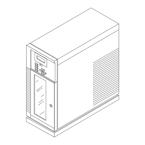
Sun StorEdge L400 Tower and Rackmount Versions FIGURE 1-1 Note – The remaining illustrations in this chapter show the rackmount version. Internal components of all versions are identical; differences are in orientation only. Sun StorEdge L400 Installation and User’s Guide • April 1998... -
Page 27: Front Panel Components
Front Panel Components for an illustration of the front panel of the tape library. FIGURE 1-2 Front door The door contains a clear, shatterproof and scratch resistant window that allows you to see the cartridges, the tape drives and the motions of the CHM. -
Page 28: Back Panel Components
Connects two internal portions of the SCSI bus together. Power supply assembly Power switch Power connector SCSI cable SCSI Remote hardware terminator reset port SCSI bus jumper blocks Back Panel FIGURE 1-3 Sun StorEdge L400 Installation and User’s Guide • April 1998... -
Page 29: Internal Components
Internal Components for an illustration of the internal components of the tape library. FIGURE 1-4 Removable tape cartridge Each holds 8 mm tape cartridges (10 maximum). The holders cartridges don’t need to be formatted or conditioned before use. Fixed cartridge holder Stores a cleaning cartridge or an additional data cartridge above the removable holder. - Page 30 Sun StorEdge L400 Installation and User’s Guide • April 1998...
-
Page 31: Preparing The Tape Library For Installation
Unpacked the tape library and check the contents against the packing slip to make sure you have the following items: A Sun StorEdge L400 tape library with one or two tape drives installed Two power cords SCSI cable (2 meters) -
Page 32: Preparing The Tape Library
1. Locate the key in your accessory kit. 2. Insert the key vertically into the lock and turn it clockwise 90 degrees (FIGURE 2-1). Lock Lock Location FIGURE 2-1 3. Pull the front door open. Sun StorEdge L400 Installation and User’s Guide • April 1998... -
Page 33: Figure
4. Attach wrist strap. 5. Reach in through the open door and remove the packing material ( FIGURE 2-2 a. Remove the large piece of packing material b. Pull the CHM towards you and push it to the top of the tape library to free it from the second piece of packing material that is inserted in the holder. -
Page 34: Removing Packing Material
First piece Removing Packing Material FIGURE 2-2 Sun StorEdge L400 Installation and User’s Guide • April 1998... -
Page 35: Figure
6. Remove the tape cartridge holder by reaching in through the door and pulling the right-side of the removable tape cartridge holder towards you while lifting its left-end slightly ( FIGURE 2-3 Removable cartridge holder Removing the Cartridge Holder FIGURE 2-3 7. -
Page 36: Installing The Tape Cartridges
If the red tab is visible, the cartridge is write protected. To write-enable a cartridge: Move the write-protect switch toward the edge of the tape cartridge. If the red tab is not visible, the cartridge is write enabled. Sun StorEdge L400 Installation and User’s Guide • April 1998... -
Page 37: Adding The Bar Code Labels
2.3.2 Adding the Bar Code Labels Center the label within the area on the edge of the cartridge ( FIGURE 2-5 Bar code labels on your 8 mm cartridges are used by the bar code scanner to gather information. Placing Bar Code Labels FIGURE 2-5 2.3.3 Placing the Tape Cartridge in the Removable... -
Page 38: Inserting A Tape Cartridge
The holder can contain up to ten cartridges. Note – Only use a holder designed for 8 mm tape cartridges. Single mounting guide Inserting a Tape Cartridge FIGURE 2-6 Sun StorEdge L400 Installation and User’s Guide • April 1998... -
Page 39: Installing The Removable Cartridge Holders
2.3.4 Installing the Removable Cartridge Holders 1. Locate the roller on the top end of the holder’s mounting plate on the interior back of the tape library ( FIGURE 2-7 2. Position the cartridge holder near the mounting plate so that the single mounting guide on the top of the holder is on the right. -
Page 40: Inserting A Cartridge In The Fixed Holder
FIGURE 2-8 Close the door and lock it by turning the key counterclockwise 90 degrees. Fixed cartridge holder Removable cartridge holder Inserting a Cartridge in the Fixed Holder FIGURE 2-8 2-10 Sun StorEdge L400 Installation and User’s Guide • April 1998... -
Page 41: Installing A Tape Library Tower Version
C H A P T E R Installing a Tape Library Tower Version This chapter explains how to install a tape library tower version. Before You Start Before you perform any of the installation procedures: Read the “Safety Agency Compliance” section at the beginning of the manual. Protect the tape library from electrostatic discharge (ESD) by placing it on an antistatic work surface and by wearing an antistatic wrist band. -
Page 42: Installation Task List
The SunOS level returned must be 5.5 or higher. Caution – For SunOS 5.5 or 5.5.1 operating systems, you must perform the procedures in Appendix B, “Modifying the st.conf File," before proceeding. Sun StorEdge L400 Installation and User’s Guide • April 1998... -
Page 43: Shutting Down The System
Shutting Down the System 1. Become superuser by typing and pressing Return. % su Password: superuser password 2. Shut down the operating system. Use either the init or shutdown commands. See the man pages for these commands or the Solaris AnswerBook online documentation. Note –... -
Page 44: Connecting The Scsi Cables
FIGURE 3-1 Power supply assembly SCSI jumper blocks SCSI terminator Power switch Power connector SCSI Cable SCSI Connectors on the Tape Library Rear Panel FIGURE 3-1 Sun StorEdge L400 Installation and User’s Guide • April 1998... -
Page 45: Scsi Buses
If the tape library is not the last physical device on the SCSI bus, plug a SCSI cable into an available connector. If the tape library is the last physical device on the SCSI bus, plug a SCSI cable into the left-end connector and the appropriate SCSI external terminator into the right-end connector. -
Page 46: Powering On The Tape Library
Note – The tape library has self-ranging voltage selection, so you do not need to change the voltage setting. Sun StorEdge L400 Installation and User’s Guide • April 1998... -
Page 47: Setting Scsi Ids
2. Press the power switch to the on position. When you power on the tape library, the following events occur: Cooling fan begins to rotate. Main Screen appears on the LCD. Tape drives perform their initiation tests. Tape library performs a 40-second, initiation test. During this test, the tape library first engages the locking solenoid in the front door, then the CHM does the following tests: Verifies its full range of motion by moving along the long axis... -
Page 48: Powering On Peripherals And The System
1. Power on your other peripherals and then your system. Note – If your system starts to reboot, interrupt the reboot process by pressing the Stop and A keys together. 2. Reboot your system using the boot -r command. Sun StorEdge L400 Installation and User’s Guide • April 1998... -
Page 49: Installing A Tape Library Rackmount Version
C H A P T E R Installing a Tape Library Rackmount Version This chapter explains how to install a tape library rackmount version. Before You Start Before you perform any of the installation procedures: Read the “Safety Agency Compliance” section in the front of this manual. Protect the tape library from electrostatic discharge (ESD) by placing it on an antistatic work surface and by wearing an antistatic wrist band. -
Page 50: Installation Overview
The SunOS level returned must be 5.5 or higher. Caution – For SunOS 5.5 or 5.5.1 operating systems, you must perform the procedures in Appendix B, “Modifying the st.conf File," before proceeding. Sun StorEdge L400 Installation and User’s Guide • April 1998... -
Page 51: Shutting Down The System
Shutting Down the System Before you can install the tape library or upgrade your hardware, you must shut down the system. If a step is omitted, the system may fail to boot, or fail to correctly configure the tape drive. 1. -
Page 52: Installing The Tape Library
Follow the instructions in the “Preparing for Service” section of your system or enclosure documentation. Be sure to: Extend the anti-tilt bar Remove or open the front panel Remove the vented rear panel Sun StorEdge L400 Installation and User’s Guide • April 1998... -
Page 53: Installing The Slide Rail Runners On The Tape Library
4.5.2 Installing the Slide Rail Runners on the Tape Library 1. Separate runners from slide rails. a. Locate the slide rails that were shipped with the tape library. b. Fully extend one slide rail until it locks. c. Press the rail release button in the center of the rail ( FIGURE 4-1 This action releases the two-part portion. -
Page 54: Installing Locking Brackets On The Tape Library
Installing Locking Brackets on the Tape Library 1. Locate the two locking brackets shipped with the tape library. 2. Attach a locking bracket on each side of the tape library using the 10-32 Phillips screws provided. Sun StorEdge L400 Installation and User’s Guide • April 1998... -
Page 55: Figure 4-3 Positioning The Locking Brackets Behind A Door
If you are installing the Sun StorEdge L400 tape library behind a bezel, mount the locking brackets with the short side facing back. Use the set of slotted holes farthest from the short side. Install the bracket so that the screws are in the middle of the slotted holes. -
Page 56: Installing Slide Rails In The Cabinet
If you are installing the Sun StorEdge L400 tape library behind a door, mount the locking brackets with the short side facing front. Use the set of slotted holes closest to the short side. Install the bracket so that the screws are in the middle of the slotted holes. -
Page 57: Figure 4-5 Placing The Slide Rails Inside The Cabinet
Rear Front Placing the Slide Rails Inside the Cabinet FIGURE 4-5 2. Select the correct mounting holes in the cabinet to use for the tape library. For mounting hole information refer to http://docs.sun.com. Select Storage & Peripherals → Rackmount Placement Matrix. 3. - Page 58 8. Repeat Step 6 and Step 7 for the other slide rail. 9. With the slide rails correctly positioned, tighten all the screws at the cabinet front and the rear. 4-10 Sun StorEdge L400 Installation and User’s Guide • April 1998...
-
Page 59: Installing The Tape Library In The Cabinet
4.5.5 Installing the Tape Library in the Cabinet Caution – The tape library shipping weight is approximately 92 pounds (41.73 kg). Use two or more people to install the tape library in the cabinet. 1. Mount the tape library on the slide rails. a. - Page 60 3. Attach the locking bracket to the cabinet rails. If you are installing the Sun StorEdge L400 tape library behind a bezel: Mounting a Tape Library Behind a Bezel FIGURE 4-9 a. Loosely install two 10-32 screws in each locking bracket using a Phillips screwdriver.
-
Page 61: Figure
If you are installing the Sun StorEdge L400 tape library behind a door: a. Select the correct cabinet rail mounting holes to use for the locking brackets. For mounting hole information refer to http://docs.sun.com. Select Storage & Peripherals → Rackmount Placement Matrix. -
Page 62: Installing The Power Cable
4. Route the power cord up through the cut-out to the power distribution unit at the side of the cabinet. 5. Plug the power cord for the tape library into the power distribution unit FIGURE 4-12 4-14 Sun StorEdge L400 Installation and User’s Guide • April 1998... - Page 63 Caution – The power distribution unit serves as the primary disconnect device for the tape library. Do not plug the tape library into a power source other than the power distribution unit. Personal injury may result if you work on a tape library that is plugged into another power source, since that power source may still be active when you work on the tape library.
-
Page 64: Connecting The Scsi Cables
( ). If you are installing FIGURE 4-13 the tape library on all three SCSI buses, the SCSI bus jumper blocks are not needed. 4-16 Sun StorEdge L400 Installation and User’s Guide • April 1998... -
Page 65: Scsi Buses
4.7.1 SCSI Buses You can separate the internal SCSI bus of the tape library into one, two, or three buses. Each drive and the robotic arm are on an individual bus. You can put the entire unit on one bus by installing the provided jumper block across the middle four SCSI connectors on the tape library rear panel. - Page 66 Repeat this step until you reach the last SCSI device. c. Ensure that the last device on the SCSI bus is properly terminated. 4-18 Sun StorEdge L400 Installation and User’s Guide • April 1998...
-
Page 67: Powering On The Tape Library
Powering On the Tape Library This section describes how to power on the tape library. The power switch and connector for the power cord are located on the back panel of the tape library FIGURE 4-11 1. Turn on the power to the cabinet. 2. -
Page 68: Powering On The System
Note – If your system starts to reboot, interrupt the reboot process by pressing the Stop and A keys together. 2. Reboot your system using the boot -r command. 4-20 Sun StorEdge L400 Installation and User’s Guide • April 1998... -
Page 69: Installing The Optional Second Tape Drive Upgrade
Installing the Optional Second Tape Drive Upgrade This chapter describes how to install the optional second tape drive upgrade in a Sun StorEdge L400 tape library equipped with one tape drive. Tape Drive in the Drive Carrier or Drive Blank In this section, drive carrier refers to a tape drive installed in a drive carrier. -
Page 70: Figure
Remove all data cartridges. 3. Turn off the power but leave the power cord connected to the wall outlet. 4. Attach a wrist strap to your wrist and to the metal chassis. Sun StorEdge L400 Installation and User’s Guide • April 1998... - Page 71 5. Loosen the two captive screws on the drive carrier faceplate ( FIGURE 5-2 Captive screw Faceplate Lever Drive carrier Screws on the Drive Carrier Faceplate FIGURE 5-2 6. Pull out the lever on the faceplate using your finger. Do not try to pull out the lever without first loosening the screws. 7.
-
Page 72: Installing The Drive Carrier Or Drive Blank
Make sure the lever closes all the way when the connection is made. 3. Tighten the two captive screws on each end of the drive carrier faceplate. 4. Remove the wrist strap. Sun StorEdge L400 Installation and User’s Guide • April 1998... -
Page 73: Operating The Tape Library
C H A P T E R Operating the Tape Library This chapter describes how to use the tape library. The basic operations of the tape library include: Understanding the operator panel Using the control modes Stopping/restarting the tape library’s operation Resetting the tape library Security options for the tape library Testing the drives and the tape library... - Page 74 Scrolls down → Scrolls right ← Scrolls left Help Goes to the Help screen Escape No action Enter Selects the item next to the arrow Reset Goes to the reset screen Sun StorEdge L400 Installation and User’s Guide • April 1998...
-
Page 75: Using The Operator Panel
6.1.1 Using the Operator Panel The Operator Panel enables you to do the following: Monitor CHM functions, including cartridge movement and placement while the tape library is operating in SCSI mode Access a menu of operations for performing such tasks as setting the CHM control mode and performing setup operations Enable or disable LCD password security Set SCSI IDs for the tape library and the two tape drives... -
Page 76: Using The Control Modes
Operator Panel. SCSI Interface mode Sequential 1 mode and Sequential 2 mode Dual Sequential mode LCD Interface mode 25-Pin or 9-Pin Serial Port mode (not supported) Sun StorEdge L400 Installation and User’s Guide • April 1998... -
Page 77: Scsi Interface Mode
6.2.0.1 SCSI Interface Mode With the SCSI Interface mode, CHM motion is controlled by a SCSI driver that allows the CHM to retrieve and replace cartridges as specified by the host through the SCSI-2 command set. Note – When you switch the tape library from SCSI Interface mode to another mode, CHM operations are temporarily halted. -
Page 78: Changing The Control Mode
Current to all of the motors is turned off. A Not Ready status is returned to the host. 3. Remove or replace a cartridge or removable cartridge holder. See Chapter 2, “Preparing the Tape Library for Installation.”. Sun StorEdge L400 Installation and User’s Guide • April 1998... -
Page 79: Resuming The Tape Library's Operation
Resuming the Tape Library’s Operation 1. Close the tape library's door. 2. Turn the key counterclock wise in the door lock to lock it. After the door is closed, Unit Attention status is returned to the host. The tape library then performs its initiation procedure. Note –... -
Page 80: Security Options For The Tape Library
Change the password (default password is 000) by pressing c. Press Enter to make the password active. Note – If you forgot the password, try entering the default password - 000. Sun StorEdge L400 Installation and User’s Guide • April 1998... -
Page 81: Tape Drive Leds
Tape Drive LEDs The two tape drives in the tape library use three LEDs to indicate diagnostic and operating states (see TABLE 6-1). Tape Drive LED States TABLE 6-1 Top LED Middle LED Bottom LED (Error/Clean) (Tape Ready) (Tape Motion) POST or reset Error or failed POST flash... -
Page 82: Testing The Tape Library
To test the robotic CHM, run the Slot Demo function from the tape library Operator Panel. No host interaction is required for this test. Make sure there is at least one tape cartridge in the tape library. 6-10 Sun StorEdge L400 Installation and User’s Guide • April 1998... -
Page 83: Media Movement Control Methods
1. Disable security, if enabled. ↓ ↑ 2. Select the Maintenance Menu by pressing , then Enter. 3. Insert a tape magazine with at least one empty slot into the tape library. ↓ ↑ 4. Select Demo Menu by pressing , then Enter. -
Page 84: Sequential Mode
6.9.3 Manual Modes The third method is to place the tapes manually into an internal drive using commands from the front panel. 6-12 Sun StorEdge L400 Installation and User’s Guide • April 1998... -
Page 85: How To Set Up Solstice Backup
1. Select the LCD interface mode. 2. Select Maintenance Menu, press enter. 3. Scroll to Diagnostics, press enter. 4. Scroll to Position to Element, press enter. 5. Select a number, press enter. Cartridge slot numbers are 1 through 20. 6. Scroll to Move Cartridge. Drive numbers are 82 and 83. - Page 86 6-14 Sun StorEdge L400 Installation and User’s Guide • April 1998...
-
Page 87: Tape Library Menu Functions
C H A P T E R Tape Library Menu Functions Primary Menu The tape library has a primary menu on the display panel from which you can access several menus. The menus you can choose are displayed by the LCD as follows: Main Screen Interface Menu... - Page 88 Scrolls right. ← Scrolls left. Help Goes to the Help screen. Escape Goes forward/backward through menus. Enter Selects the item next to the arrow. Reset Goes to the reset screen. Sun StorEdge L400 Installation and User’s Guide • April 1998...
-
Page 89: Interface Menu
Interface Menu The Interface Menu allows you to put the tape library into various modes from which you can control the tape library. The Interface Menu consists of the following submenus: Control mode Configure 25-Pin Port (not supported) Configure 9-Pin Port (not supported) Configure 4-Pin Port (not supported) 7.2.1 Control Mode... -
Page 90: Scsi Interface Mode
Push the square-shaped Eject button to the right of the LEDs on the tape drive. The tape unloads from the tape drive. The tape library ignores the fixed slot in all sequential modes. c. Close the door. Sun StorEdge L400 Installation and User’s Guide • April 1998... -
Page 91: Running The Sundiag Or Sunvts System Exerciser
The following chart explains what each sequential mode does. Sequential Mode Definitions TABLE 7-1 Sequential 1 CHM picks cartridges from the holder sequentially and processes them in Drive 1 (the right drive) Sequential 2 CHM picks cartridges from the holder sequentially and processes them in Drive 2 (the left drive) Dual Sequential CHM picks ten cartridges from magazine 0 for Drive 1... -
Page 92: 25-Pin, 9-Pin, And 4-Pin Serial Port Modes
The tape library is configured with default SCSI IDs for the CHM and for each tape drive. This section describes how to view the default settings and change them, if necessary. SCSI IDs can be viewed and changed from the Operator Panel (FIGURE 6-1). Sun StorEdge L400 Installation and User’s Guide • April 1998... - Page 93 Note – Use probe-scsi-all at the ok prompt to determine the SCSI IDs that are currently set. You can use the Configuration Menu to change the SCSI IDs of the tape library (LIB) and the cartridge tape subsystems (CTSs). Each device (the library and the two CTSs) must have separate SCSI IDs.
-
Page 94: Sequential Options
Stops processing cartridges after processing the last cartridge. Note – The loop and restart options are application specific. 7.3.3.1 Restart Option ↓ ↑ 1. Select the Configuration Menu by pressing , then Enter. Sun StorEdge L400 Installation and User’s Guide • April 1998... -
Page 95: Loop Option
↓ ↑ 2. Select Sequential Options by pressing , then Enter. The following screen is displayed. → Loop: OFF → Restart: Loop2: Restart2: ↑ ↓ 3. Select Restart for tape drive 1 or Restart2 for tape drive 2 by pressing ←... -
Page 96: Set Date
Increases the hours, minutes, or seconds. ↓ Decreases the hours, minutes, or seconds. → Moves to the column on the right. ← Moves to the column on the left. 7-10 Sun StorEdge L400 Installation and User’s Guide • April 1998... -
Page 97: Set Security
7.3.8 Set Security The security option allows you to prevent a user from inadvertently changing important settings and operations. Note – Security remains in effect after resetting the tape library. When security is enabled, a user cannot access the following activities: Changing the control mode Changing the SCSI IDs Changing the library serial number... -
Page 98: Use Mammoth
The Maintenance Menu consists of the following submenus: Clean drive menu Demo menu Diagnostics menu 7.4.1 Clean Drive Menu To clean the tape drives, see Section 8.2, “Cleaning Tape Drives.” 7-12 Sun StorEdge L400 Installation and User’s Guide • April 1998... -
Page 99: Demo Menu
7.4.2 Demo Menu The Demo Menu includes: Drive Demo Causes the CHM to move randomly between slots in removable cartridge holder, the fixed cartridge slot, and the tape drives. Slot Demo Causes the CHM to move cartridges randomly between slots of removable cartridge holder, and the fixed cartridge holder. - Page 100 Indicates the number of cycles that have run so far. NN- NN Indicates the source and destination element indexes of the current move. To stop the demo, press Escape and Enter. 7-14 Sun StorEdge L400 Installation and User’s Guide • April 1998...
-
Page 101: Diagnostics Menu
7.4.3 Diagnostics Menu The Diagnostics Menu enables you to perform a variety of diagnostic ↑ ↓ functions. Use to scroll up or to scroll down. Before you perform diagnostics, make certain you know the element indexes for the components you will exercise. See TABLE 7-3 Element Indexes for the Tape Library Parts TABLE 7-3... -
Page 102: Self Test
To abort the Self Test diagnostic, press Escape and Enter. 7.4.3.2 Position to Element Test This diagnostic positions the CHM in front of a tape drive, cleaning cartridge slot, or a particular slot in the cartridge holder. 7-16 Sun StorEdge L400 Installation and User’s Guide • April 1998... -
Page 103: Park Test
↓ ↑ 1. Select the Maintenance Menu by pressing , then Enter. ↓ ↑, 2. Select the Diagnostics Menu by pressing then Enter. ↓ ↑ 3. Select Position to Element by pressing , then Enter. The following screen is displayed: Set Destination ↑... -
Page 104: Scan Test
, then Enter. ↓ ↑ 3. Select Scan by pressing , then Enter. The bar code scanner scans all the elements. To abort this diagnostic, press Escape and Enter. 7-18 Sun StorEdge L400 Installation and User’s Guide • April 1998... -
Page 105: Scan With Range Test
7.4.3.6 Scan With Range Test The Scan With Range test scans a range of elements and stores the information in the cartridge inventory. Scan errors and the contents of labels are displayed on the Label Information screen. ↓ ↑ 1. Select the Maintenance Menu by pressing , then Enter. -
Page 106: Home Chm Test
5. Select the number of cycles (in increments of ten) you want the Cycle Pick/ ↑ ↓ Place to run by pressing , then Enter. The test picks a cartridge from the element you specify and places it back in the same element. 7-20 Sun StorEdge L400 Installation and User’s Guide • April 1998... -
Page 107: Cycle Gripper Test
To abort this diagnostic, press Escape and Enter. 7.4.3.10 Cycle Gripper Test The Cycle Gripper test opens and closes the gripper the number of times you specify. ↓ ↑ 1. Select the Maintenance Menu by pressing , then Enter. 2. Select the Diagnostics Menu by pressing Escape. ↓... -
Page 108: Cycle L Axis Test
The Cycle Solenoid test exercises the solenoid that controls the locking mechanism on the front door. ↓ ↑, 1. Select the Maintenance Menu by pressing then Enter. ↓ ↑ 2. Select the Diagnostics Menu by pressing , then Enter. 7-22 Sun StorEdge L400 Installation and User’s Guide • April 1998... -
Page 109: Library Information Menu
↓ ↑ 3. Select Cycle Solenoid by pressing , then Enter. The system displays the following screen: Set Cycles ↑ Increase ↓ Decrease 4. Select the number of cycles, in increments of ten, (up to 250) you want the Cycle ↑... - Page 110 Indicates whether the SCSI security feature is on or off. Write Line 1 - 4 Indicates whether the text displayed on each of the four lines on the main menu is defined for the LCD Mode page. 7-24 Sun StorEdge L400 Installation and User’s Guide • April 1998...
-
Page 111: Statistics
shows the default element addresses for the tape library. FIGURE 7-2 83 82 Cartridge slots 1-10 Fixed slot 19 18 17 16 15 14 13 12 Cartridge slots 11-20 Default Element Addresses for the Tape Library FIGURE 7-2 SCSI Reservations The SCSI Reservations command is not supported on Sun systems. - Page 112 Number of times the library retried picking from that element. Retries: Put Number of times the library retried placing a cartridge in that element. Retries: Scan Number of times the library retried scanning that element. 7-26 Sun StorEdge L400 Installation and User’s Guide • April 1998...
-
Page 113: System Sensors
7.5.3 System Sensors The System Sensors display lets you check the current status of the internal mechanical sensors. ↓ ↑ 1. Select the Library Info Menu by pressing , then Enter. ↓ ↑ 2. Select System Sensors by pressing , then Enter. The system displays the Digital Sensors screen followed by the Analog Sensors ↓... -
Page 114: Command History
9-29-94 04441 3. Press ↑ and ↓ to scroll through the entries. The most recent event in the history buffer is displayed first. 4. To exit Command History, press Escape. 7-28 Sun StorEdge L400 Installation and User’s Guide • April 1998... -
Page 115: Inventory Menu
to understand what the Command History information means. TABLE 7-7 Field Descriptions of Command History TABLE 7-7 Shown in sample Field Name Description IDX (Index) Line number of this event within the history buffer ( 000 - 299). 000 - most recent event MOVE From Process name that caused this event. -
Page 116: Bar Code Label Information
The bar code scanner could not read the bar code label because there was no label on the cartridge. The bar code scanner could not read the bar code label because the label was unreadable. 7-30 Sun StorEdge L400 Installation and User’s Guide • April 1998... -
Page 117: Element Occupied Information
Label Error Field Error Messages (Continued) TABLE 7-8 Error Code Description The bar code scanner could not read the bar code label because the cartridge holder or tape drive was not installed. The bar code scanner could not read the bar code label because a Direct Memory Access (DMA) overrun occurred. -
Page 118: Element Position Information
To display element position information: ↓ ↑ 1. Select the Library Info Menu by pressing , then Enter. ↓ ↑ 2. Select the Inventory Menu by pressing , then Enter. 7-32 Sun StorEdge L400 Installation and User’s Guide • April 1998... -
Page 119: Drive Info Menu
↓ ↑ 3. Select Position Info by pressing by pressing , then Enter. The following screen is displayed: ELEM POS, INX= 0: Long Axis: Depth ↓ 4. Display the following information for each element index by pressing ↓ or ↑. The following chart displays the information for each index: Displays the element index. -
Page 120: Tape Drive Leds
The occupied information is reliable. The door has been opened or another interruption has occurred so the occupied information may not be reliable. 7.5.6.1 Tape Drive LEDs See Section 6.7, “Tape Drive LEDs.” 7-34 Sun StorEdge L400 Installation and User’s Guide • April 1998... - Page 121 7.5.6.2 Cleaning Tape Drives Tape drives need to be cleaned once every 72 motion hours. Note – When cleaning the tape drive, use a Sun approved 8 mm cleaning cartridge. Each drive keeps track of tape motion hours internally. When tape motion hours have reached the limit, the following activities occur: The tape drive informs the library that it needs cleaning.
- Page 122 2. Eject a tape from the drive, if necessary, by pressing the Unload button. 3. Manually insert a cleaning cartridge into the appropriate tape drive. The tape drive automatically ejects the cleaning cartridge when cleaning is complete. 7-36 Sun StorEdge L400 Installation and User’s Guide • April 1998...
-
Page 123: Cleaning Tape Drives
C H A P T E R Maintaining the Tape Library This chapter describes how to clean and service various components of the tape library. To help the tape library perform at a optimum level, you should perform the preventive maintenance procedures described in this chapter. Be sure to read through this chapter and the “Safety Agency Compliance”... -
Page 124: Caring For Tape Cartridges
Make sure the cartridge is at the same temperature as the drive before using it. Never open the tape access door on the cartridge and touch the surface of the tape Sun StorEdge L400 Installation and User’s Guide • April 1998... -
Page 125: Scsi Information
A P P E N D I X SCSI Information This appendix describes the Small Computer Systems Interface (SCSI). Topics covered in this appendix include: SCSI ports and connections SCSI bus length SCSI bus termination information SCSI Ports and Connections If fast SCSI devices and old-style connectors must be used in the same system, the old-style connectors should be connected to a separate SCSI port that does not contain fast SCSI devices. -
Page 126: Direct Connection
Note – Devices with the old-style connectors (3-row 50-pin D connectors or 50-pin ribbon connectors) should not be used on the same bus (daisy chained) with fast SCSI devices. Sun StorEdge L400 Installation and User’s Guide • April 1998... -
Page 127: Scsi Bus Length
SCSI Bus Length A bus is a signal route to which several parts of a computer system can be connected so that signals can pass between them. The total length of a SCSI bus includes: The length of the external SCSI cable plus The length of the internal SCSI buses for the device and the system Your desktop system performance is reliable with a maximum SCSI bus length of 20 feet (6 meters), shown in Figure B-1. -
Page 128: Additional Scsi Buses
SBus slots, it begins probing the on-board SCSI bus, then SBus slot 1, then SBus slot 2, and so on. Because slot 2 contains the first FSBE/S SBus card, this is SCSI bus 1. Sun StorEdge L400 Installation and User’s Guide • April 1998... -
Page 129: Terminating Scsi Devices
Terminating SCSI Devices You must attach a regulated SCSI terminator to the SCSI port at the end of the SCSI bus. A terminator holds the bus at a predetermined signal level when the bus is not active and maintains impedance matching. All SCSI daisy-chains must be terminated at the last unit attached to the SCSI bus. - Page 130 If fast SCSI devices and old-style connectors must be used in the same system, the old-style connectors should be connected to a separate SCSI port that does not contain fast SCSI devices. Sun StorEdge L400 Installation and User’s Guide • April 1998...
-
Page 131: Modifying The St.conf File
The Solaris software environment recognizes all tape devices that were supported by Sun when your operating system was released. If your system uses SunOS releases 5.5 or 5.5.1, which were released before the Sun StorEdge L400 tape library, you need to modify the /kernel/drv/st.conf file so that your Solaris software will recognize the tape drives inside of the tape library. - Page 132 Note – The first two lines of the example end in commas. The last line in the example ends with a semi-colon. You must follow this format when adding multiple tape devices to the st.conf file. Sun StorEdge L400 Installation and User’s Guide • April 1998...
-
Page 133: Modifying The St.conf File
B.1.3 Configuration Values The third section contains the values that will be used to configure the tape devices. It has lines like: #ARCH_Python 1,0x2c,0,0xde39,4,0x00,0x8c,0x8c,0x8c,3; The part of the line before the equal sign (=) is the string that is linked to the values that will be used to configure a tape device. - Page 134 On the next line, add the following entry exactly as shown: mam-data=1,0x29,0,0x1de39,1,0x7f,0; Note – All lines in this section end with semicolons. f. Save and exit the file. 4. Continue the installation procedure. Sun StorEdge L400 Installation and User’s Guide • April 1998...
-
Page 135: Mm Tape Drive Information
A P P E N D I X 8 mm Tape Drive Information Tape Drives The tape drive used in the Sun StorEdge L400 tape library is model 8900. This 8 mm device incorporates internal data compression and uses AME data grade tapes only. Carrier... -
Page 136: Tape Formats And Capacities
TABLE C-1 One disadvantage of this approach is that this data format is not readable by the earlier drives other than the 8900 because they do not incorporate hardware data compression. Sun StorEdge L400 Installation and User’s Guide • April 1998... -
Page 137: Software Data Compression
Note – Never use two compression methods on the same data. The use of a second compression method rarely compresses the data further; double compressed data can actually expand in size. C.4.2 Software Data Compression Data compression can be done via software. The compress and restore commands are used for writing and reading, respectively. -
Page 138: Tape Utilities
If the n is not present, a rewind is implied and will be done after the operation. The mt rewind command is used to issue rewind commands. Sun StorEdge L400 Installation and User’s Guide • April 1998... -
Page 139: Tar
The mt offline command ejects media from the tape drive. This is used for sequential mode operation as detailed above. If the robotic mechanism is in sequential mode, it will automatically load the next tape. C.6.2 The tar command is a basic utility for writing to and reading from the tape drives. Single files, multiple files, or entire directories can be specified. - Page 140 Sun StorEdge L400 Installation and User’s Guide • April 1998...
-
Page 141: Error Codes
A P P E N D I X Error Codes This appendix contains the error codes that may appear on the main screen. The tables in this appendix contain the following information: Additional Sense Code. Corresponds to byte 12 of the sense data returned in response to the REQUEST SENSE command. -
Page 142: Hardware Errors
Press the tape drive eject button and wait for the could not successfully pick a cartridge cartridge to be unloaded, or redirect the CHM to because it was still loaded in the drive. another location. Sun StorEdge L400 Installation and User’s Guide • April 1998... - Page 143 Hardware Errors by Error Code (Continued) TABLE D-1 Error Description Corrective Action Number PICK MECH. FAILURE. The CHM Open the door and look for anything that might be could not successfully pick from a full obstructing the gripper. cartridge slot. Make sure the library and tape drives are not being used by any host, then press Reset on the operator panel.
- Page 144 If there are no obstructions, contact your service provider. D AXIS FAILED HOME. The library Contact your service provider. could not determine the home position for the drum. Sun StorEdge L400 Installation and User’s Guide • April 1998...
- Page 145 Hardware Errors by Error Code (Continued) TABLE D-1 Error Description Corrective Action Number NO LABEL. The bar code scanner If present, this error appears on the Label Info screen. could not read the bar code label If the cartridge does not have a bar code label, place because there was no label on the a label on the cartridge.
- Page 146 CHM. If a tape drive is installed, make sure that the drive carrier is correctly seated. If the error persists, contact your service provider. Sun StorEdge L400 Installation and User’s Guide • April 1998...
- Page 147 Hardware Errors by Error Code (Continued) TABLE D-1 Error Description Corrective Action Number NO MAGAZINE. There is no If no magazine is installed in that location, redirect magazine installed in this location. the CHM. If a magazine is installed, make sure that it is correctly seated on the mounting plate.
-
Page 148: Scsi Sense Key Errors
SCSI bus was reset. Bh - Aborted The tape library aborted a command Retry the operation. Command (typically operator aborted). Sun StorEdge L400 Installation and User’s Guide • April 1998... -
Page 149: Not Ready-Sense Key 2H
D.2.1 Not Ready—Sense Key 2h During a Not Ready condition, the tape library returns a Check Condition status in response to each motion command until the Not Ready condition is removed. During this time, the sense key is set to Not Ready and the ASC and ASCQ are set to codes specifying that the tape library is not ready. - Page 150 Internal ROM failure. +24-volt power supply failure. +12-volt power supply failure. -12-volt power supply failure. Digital/analog converter failure. The front door is open or the door solenoid is malfunctioning. D-10 Sun StorEdge L400 Installation and User’s Guide • April 1998...
- Page 151 Hardware Error Sense Key (4h) ASC and ASCQ Values (Continued) TABLE D-4 ASCQ Display Description Byte 12 Byte 13 Panel Number The tape library was not in the correct control mode when the command was executed. To invoke commands from the Maintenance Menu, the tape library must be in LCD Interface mode.
-
Page 152: Illegal Request-Sense Key 5H
A media load or unload operation was prevented with a PREVENT/ ALLOW MEDIUM REMOVAL command. There was a cartridge in the grab base during power up, before a cartridge move, or before a diagnostic test. D-12 Sun StorEdge L400 Installation and User’s Guide • April 1998... -
Page 153: Unit Attention-Sense Key 6H
Illegal Request Sense Key (5h) ASC and ASCQ Values (Continued) TABLE D-5 ASCQ Description Byte 12 Byte 13 The source cartridge magazine is not installed. The destination cartridge magazine is not installed. The source tape drive is not installed. The destination tape drive is not installed. The bar code scanner is not installed. -
Page 154: Aborted Command-Sense Key Bh
The tape library received an Initiator Detected Error message at an inappropriate time. The initiator rejected a Restore Data Pointers message that the tape library sent in response to the Initiator Detected Error message. D-14 Sun StorEdge L400 Installation and User’s Guide • April 1998... -
Page 155: Glossary
Glossary The SCSI cable that serves as a link for passing signals between the computer system and the tape library. Command descriptor block. The structure used to communicate commands from an initiator to a target. Cartridge handling mechanism. The robotic assembly that retrieves and replaces cartridges. - Page 156 A unique identifier assigned to each device or subsystem on the SCSI bus. Also referred to as SCSI address. target A bus device (usually a controller) that performs an operation requested by an initiator. The tape library is a target. Sun StorEdge L400 Installation and User’s Guide • April 1998 Glossary-2...
- Page 157 Index NUMERICS 04h, D-9 aborted command, ASC and ASCQ values, D-14 15h, D-10 additional SCSI buses, A-4 1Ah, D-12 Additional Sense Code, D-1 21h, D-12 analog system sensors 24h, D-12 descriptions, 7-28 25h, D-12 25-pin serial port mode, 7-6 26h, D-12 28h, D-13 Back Light, 7-9 29h, D-13...
- Page 158 3-4, 4-16 fixed cartridge holder, 1-1 date, setting, 7-10 fixed cartridge slot default element address, 7-25 element index, 7-15 default SCSI IDs, 7-6 Demu Menu, submenus, 7-13 Index-2 Sun StorEdge L400 Installation and User’s Guide • April 1998...
- Page 159 Loop 2, 7-8 loop option hardware error setting, 7-9 ASC and ASCQ values, D-9 codes, D-2 history events displaying, 7-28 Home CHM, 7-16 main screen, 6-1 Home CHM test maintenance information, xxi running, 7-20 Maintenance Menu Home Gripper, 7-15 submenus, 7-12 Home Gripper test maximum SCSI bus length, 3-1, 4-1, A-3 running, 7-19...
- Page 160 7-9 SCSI IDs, 7-7 setting the restart option, 7-8 setting, 7-7 setting the SCSI ID, 7-7 SCSI Interface mode, 6-5 shut down the system, 4-3 Index-4 Sun StorEdge L400 Installation and User’s Guide • April 1998...
- Page 161 signal route, A-3 unit attention single-phase power systems, 3-6 ASC and ASCQ values, D-13 Slot Demo, 6-11, 7-14 unload button slot demo location, 5-2 running, 6-11, 7-14 unloading Small Computer Systems Interface (SCSI), A-1 tape drive, 7-4 st.conf file, B-1 upgrade, optional second tape drive, 5-1 statistics displalying, 7-26...
- Page 162 Index-6 Sun StorEdge L400 Installation and User’s Guide • April 1998...
Need help?
Do you have a question about the StorEdge L400 and is the answer not in the manual?
Questions and answers