4.3 Technical data ......................... 14 4.4 Possible combinations ....................16 4.4.1 Installation overview of IMAGE1 S CONNECT ........... 16 4.4.2 Installation overview of IMAGE1 S CONNECT II ..........17 4.5 Symbols employed ......................18 4.5.1 Symbols on the packaging ................. 18 4.5.2 Symbols on the product ...
Page 4
Table of contents 6.2.2 OPAL1 ......................... 34 6.2.3 Display (Live menu) ..................... 35 6.3 Setup menu ........................36 6.3.1 Display (Setup menu) ..................39 6.3.2 Network ......................40 6.4 Patient data privacy ......................42 6.5 Switching off the product ....................45 7 Maintenance, servicing, repairs, and disposal ................. 46 7.1 Maintenance ...
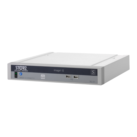
1.3 Scope These instructions for use apply to the following products up to and including software version 4.3: Product name Item number IMAGE1 S CONNECT TC200US IMAGE1 S CONNECT II TC201US IMAGE1 S H3-LINK TC300US IMAGE1 S X-LINK TC301US IMAGE1 S D-LINK...
General information Step 1 ð Interim result of an action Step 2 ð Result of a completed action Actions in safety notes or in the case of a single step: Step 1 Lists Numbered list – Unnumbered list, 1st level –...
Normal use 2 Normal use 2.1 Intended use IMAGE1 S The IMAGE1 S is a camera control unit for use with camera heads or videoscopes and is used for visualizing and documenting endoscopic and microscopic procedures. 2.2 Indications IMAGE1 S is a camera control unit (CCU) for use with camera heads or video endoscopes for the visualization and documentation of endoscopic and microscopic procedures.
Safety and warning 3 Safety and warning WARNING Danger due to non-observance of warnings and safety notes This chapter contains warnings and safety notes structured according to hazards and risks. 1. Carefully read and observe all warnings and safety notes. 2.
Do not touch the output jacks of the product and the patient at the same time during use Do not open the product. Use either the power cord supplied by KARL STORZ or a power cord which has the same properties and which bears a national mark of conformity.
Safety and warning RFID) emit electromagnetic radiation, the function of the product may be impaired. High- frequency communication equipment can affect electrical medical products and impair their performance. Observe the information on electromagnetic compatibility, see chapter Electromagnetic compatibility [p. 53]. The discharge of a defibrillator can cause image loss. If the image has not recovered after 4 seconds, switch the camera control unit off and on again.
Power switch D3-LINK camera connection White balance IMAGE1 S D3-LINK (TC302US) USB port IMAGE1 S X-LINK (TC301US) H3-LINK camera connection IMAGE1 S H3-LINK (TC300US) X-LINK camera connection 10 IMAGE1 S CONNECT (TC200US) Instructions for use • IMAGE1 S • 705LZA_EN_V2.1_05-2022_IFU_FDA...
Page 12
Product description Rear side of IMAGE1 S CONNECT LINK input ports HD DVI-D video output sockets Potential equalization connector 3G-SDI video output SCB input/output sockets Mains sockets (KARL STORZ Communication Bus) LAN interface, KS HIVE interface Potential equalization connector USB interface 10 LINK output Instructions for use •...
Page 13
Power switch D3-LINK camera connection White balance IMAGE1 S D-LINK (TC302US) USB port IMAGE1 S X-LINK (TC301US) 4U-LINK camera connection IMAGE1 S 4U-LINK (TC304US) X-LINK camera connection 10 IMAGE1 S CONNECT II (TC201US) Instructions for use • IMAGE1 S • 705LZA_EN_V2.1_05-2022_IFU_FDA...
Product description Rear side of IMAGE1 S CONNECT II LAN interface, KS HIVE interface Mains sockets LINK input ports Potential equalization connector SCB input/output sockets USB interface (KARL STORZ Communication Bus) 12G/3G SDI video output 10 Potential equalization connector DisplayPort video output sockets...
Page 15
Product description IMAGE1 S CONNECT II Description Value 4K and HD video outputs 2x DP 1x 12G/3G SDI 1x DVI-D Signal output format 3,840 x 2,160p, 50/60 Hz for DP and 12G-SDI 1,920 x 1,080p, 50/60 Hz for 3G-SDI and DVI- LINK input ports KS HIVE interface RJ45 USB interface 4x USB Image format JPEG...
Only compatible products may be combined with the CONNECT modules and LINK modules, see chapter Accessories [p. 48]. KARL STORZ recommends combining only CONNECT modules and LINK modules with the same software version. The following products are required for navigation and input: –...
Product description 4.4.2 Installation overview of IMAGE1 S CONNECT II To use OPAL1* fluorescence imaging, the IMAGE1 S 4U-LINK (TC304US) and Power LED Rubina (TL400) must also be connected via a sync cable when using the TIPCAM1 Rubina. * OPAL1 is NOT available for PDD in the USA.
Product description 4.5 Symbols employed 4.5.1 Symbols on the packaging Symbol Meaning Manufacturer Date of manufacture Medical device Article no. Serial number Number of products in the product packaging Instructions for use • IMAGE1 S • 705LZA_EN_V2.1_05-2022_IFU_FDA...
EU directives. A code number after the CE mark indicates the responsible notified body. The EU directives relevant to the product can be found in the EU Decla- ration of Conformity, which can be requested from KARL STORZ. This side up 4.5.2 Symbols on the product...
Product description Symbol Meaning Applied part type CF defibrillation protection Potential equalization connector Prevention of pollution by electronic devices Separate collection of electrical and electronic devices. Do not dispose of in household refuse. Consult the printed or electronic instructions for use 4.5.3 Symbols on the user interface Symbol Meaning...
Page 21
Product description Symbol Meaning Memory/Eject Patient Presets Setup menu Info Brightness Print Video Image Image flip Enhance Parameter regions Instructions for use • IMAGE1 S • 705LZA_EN_V2.1_05-2022_IFU_FDA...
Page 22
Product description Symbol Meaning Patient data privacy Dashboard Live menu Image Software license Exit Frequency Display Contact information Date and time Camera buttons White balance Instructions for use • IMAGE1 S • 705LZA_EN_V2.1_05-2022_IFU_FDA...
Preparation 5 Preparation 5.1 Unpacking the product Carefully remove the product and accessories from the packaging. Check the delivery for missing items and any possible damage. In the case of damage, hidden defects, and short deliveries, document their nature and extent and contact the manufacturer or supplier immediately.
Page 25
Pull back the protection device of the SCB connector and insert the connector into one of the SCB sockets. Connect the other end of the cable to a KARL STORZ SCB control device (KARL STORZ Communication Bus). Instructions for use • IMAGE1 S • 705LZA_EN_V2.1_05-2022_IFU_FDA...
Page 26
Preparation Insert the OR1 patch cable into the KS HIVE/LAN interface. Connect the other end of the cable to a KS HIVE-compatible product, e.g., Power LED Rubina (TL400), AIDA (WD300, WD350), OR1 HIVE router (WO10307). Connect the IMAGE1 S 4U-LINK (TC304US) and Power LED Rubina (TL400) to a sync cable if the products are being used with the TIPCAM1 Rubina.
Preparation 15. Connect the power cord. Push the power plug fully into the power socket. 16. Push the power plugs fully into the power sockets of the LINK modules. 17. Connect the power plugs to the power sockets. Use the network device only in a protected network with firewall and router. 5.5 Putting the product into operation WARNING Hot surfaces! Risk of burns!
Page 28
ð The connected LINK modules start automatically. Format the USB storage device as FAT 32. Connect the USB storage device to the IMAGE1 S CONNECT to store still images or videos. Do not connect more than 1 USB storage device. Check the values set for the primary source and the secondary source.
Preparation 5.6 Performing the white balance The white balance must be performed again after replacing the endoscope. Failure to perform proper white balance of system may result in color distortion. Ensure that the imaging instrument is connected and a live image appears on the monitor.
Application 6 Application 6.1 Dashboard The dashboard displays the LINK modules, peripheral devices, and recommended accessories connected to the LINK module. Unconnected peripheral devices, recommended accessories, and the LINK modules are shown in gray. If more than one LINK module is used, the IMAGE1 S with the Auto Source Detection function automatically recognizes the module to which a camera head is connected.
Application 10. Tap the Memory/Eject button to eject the USB storage device. Data may be lost if the USB storage device is not ejected. ð The USB storage device can be removed. 11. Tap the Presets button. 12. If presets have been defined in the Setup menu, select a preset. 13.
Page 32
Application On the Memory/Eject button, read off the amount of used storage space on the connected USB storage device. On the Memory/Eject button to eject the USB storage device. Data may be lost if the USB storage device is not ejected. ð...
Page 33
Application 23. Tab the Zoom button to enlarge or reduce the display. 24. Select Adaptive Zoom in the menue Zoom . The menu is available if the following products are connected: – IMAGE1 S CONNECT II (TC201US) and a 4U-LINK in combination with 4U camera heads (TH120 or TH121) –...
Application 6.2.1 Enhance (S-Technologies) Tap the Enhance (S-Technologies) button. ð The following settings are possible: – CLARA: A specially optimized algorithm reduces disruptive shadows and ensures more even brightness perception of the endoscopic image. – CHROMA: Improves the perception of fine structures via contrast enhancements, particularly in the red area.
Application 6.2.3 Display (Live menu) Tap the Display button in the Live menu. Select one of the 4 display modes for the TIPCAM1 Rubina in Display Mode: – 2D: 2D image without horizon control – 2D Autorotation: 2D image with digital horizon control –...
Application 6.3 Setup menu In the Setup menu, the general settings and the LINK-specific settings can be changed and saved as a preset. If the 2D image is displayed, no menu structure appears in the image. Open the Setup menu using one of the following options: Press the Setup button on the dashboard.
Page 37
Application 10. Tap the Module Information button to call up information about the CONNECT module, the connected LINK modules, and the camera heads or videoendoscopes. 11. Tap the General button to apply the general settings. 12. Tap the Parameter Regions button to adjust the display of additional information from connected SCB devices and KS HIVE devices.
Page 38
Application 16. Tap the Capture button to apply settings for capturing the live image. 17. Use Image Capture Preview Mode to set how the frozen image or live image is to be displayed. 18. If AIDA is connected, select full screen. 19.
Application 32. Tap the Software Licenses button to view a list of the open source software included in the product, and the open source software license terms. 6.3.1 Display (Setup menu) Tap the Display button in the Setup menu. ð The following menu appears: In PIP Layout, select a layout to adapt the picture-in-picture (PiP) function display.
Application Select the Display Language and the Keyboard Language. 10. Open the Autoswitch Angle Interface drop-down menu and select one of the following settings for the autoswitch limits display behavior when a TIPCAM1 Rubina is connected: – One line on approach –...
Page 41
Application Tap the Network button. ð The following information appears: In Patient Data Privacy, enter the password to access the Network menu, see chapter Patient data privacy [p. 42]. Alternatively, enter the password when opening the Network menu for the first time. In KS HIVE Device Integration, switch the KS HIVE communication interface on or off as required.
Do not record sensitive patient information including patient’s face, name, social security number, etc. KARL STORZ assumes no legal liability or responsibility for the loss, accuracy, damage, or disclosure of patient data that has been managed using IMAGE1 S. The patient data administration functions (e.g. entry, access, display, storage and transfer) must be activated manually.
Page 43
Application Repeat the password in the second line and confirm it. ð A prompt appears. ð The menu can be used once the password has been entered again. Activate the Increased Patient Data Privacy setting to apply the cybersecurity presets. ð...
Page 44
Application Setting Description Default setting Display Duration Specify the display duration for the Never patient data. Show Patient Tiles Specify whether the Patient tile is to appear on the dashboard and in the Live menu. Enable the printing of Patient Data Specify whether prints will be la- on Prints beled with patient information or...
Application 6.5 Switching off the product Switch the product off with the power switch. Instructions for use • IMAGE1 S • 705LZA_EN_V2.1_05-2022_IFU_FDA...
Measure the patient leakage current. 7.3 Repairing the product Repair work may only be performed by KARL STORZ or by a company authorized by KARL STORZ. The maintenance steps described in this instruction manual are exempt from this rule. Please contact your local [Product/Brand variable] subsidiary or authorized dealer (see the list of subsidiaries).
Page 47
Maintenance, servicing, repairs, and disposal Within the scope of application of this directive, KARL STORZ SE & Co. KG is responsible for the proper disposal of this product. The product must be disposed of in accordance with the applicable national laws and regulations at a suitable collection point for the reprocessing of electrical and electronic equipment.
Accessories and spare parts 8 Accessories and spare parts 8.1 Accessories NOTE: Not all accessories are offered in all regions. Basic equipment Article Order no. Videoendoscope adaptor 0° TC001 Videoendoscope adaptor 90° TC013 IMAGE 1 FULL HD extension cable, length 520 cm, for use with 22220072 all IMAGE 1 HD camera heads –...
Page 49
Accessories and spare parts Compatible camera heads for IMAGE1 S H3-LINK with S-Technologies Item Order no. IMAGE1 S H3-Z three-chip FULL HD camera head TH100 IMAGE1 S H3-Z three-chip FULL HD camera head TH101 IMAGE1 S H3-Z FI three-chip FULL HD camera head TH102 IMAGE1 S H3-P three-chip FULL HD pendulum camera head TH103...
Page 50
Accessories and spare parts Item Order no. Video rhino-laryngoscope 11101VN Video rhino-laryngoscope 11101VPS Video rhino-laryngoscope 11101VNS HD Video rhino-laryngoscope 11101HD Video-gastroscope 9.3/2.8/1,100 13821NKS Slim gastroscope 5.9/2.0/1,100 13820NKS Video-gastroscope 9.7/2.8/1,100 13801NKS Video duodenoscope 12.6/4.2/1,260 13885NKS Video colonoscope 12.9/3.8/1,600 13925NKS Video colonoscope 10.6/2.8/1,600 13907NKS Video colonoscope 13/3.8/1,600 13905NKS...
Page 51
TIPCAM1 S 3D, 45°, dia. 4 mm 28164FA3D VITOM 3D, dia. 4 mm TH200 Compatible camera heads and videoendoscopes for IMAGE1 S 4U-LINK with S- Technologies in combination with IMAGE1 S CONNECT II Item Order no. IMAGE1 S 4U TH120 IMAGE1 S 4U Rubina TH121 TIPCAM1 Rubina, 0°...
Page 52
Accessories and spare parts Operable KS HIVE light sources Item Order no. Power LED Rubina TL400 Operable SCB insufflators Item Order no. THERMOFLATOR SCB 26432020-1 ENDOFLATOR SCB 26430520-1 ENDOFLATOR 40 UI400 ENDOFLATOR 50 UI500 3D monitors Item Order no. 3D monitor (FHD), 26" 9826NB-3D 3D monitor (FHD), 32"...
Electromagnetic compatibility 9 Electromagnetic compatibility 9.1 General notes on the operating environment The product is suitable for use in professional healthcare settings. Professional healthcare facilities include physician offices, dental offices, limited care facilities, freestanding surgical centers, freestanding birth centers, multiple treatment facilities, hospitals (emergency rooms, patient rooms, intensive care, surgical rooms, outside the HF-shielded room of an ME system for MRT).
Page 54
Electromagnetic compatibility System cables and maximum lengths used for EMC compliance. Type Shield Längth [m] Ferrite LINK cable (IML Interconnection of intermodule cable) LINK signals BNC to BNC (12G- Connection of 3G/12G-SDI video SDI cable) signals Connection of DVI signals 4-pin Mini DIN Connection of SCB signals Power cord...
Page 55
Electromagnetic compatibility Interference im- EN/IEC 60601 test Compliance level Electromagnetic envi- munity tests level ronment – guidelines 100% for 250/300 cy- 100% for 250/300 cy- ated with an uninter- cles cles ruptible power supply or a battery. Magnetic field at 30 A/m at 50 Hz / 30 A/m at 50 Hz / If image distortion oc- the power fre-...
Page 56
Electromagnetic compatibility Test fre- Frequency Radio service Modulation Immunity Compliance quency band test level level 1720 1700 – 1990 GSM 1800, Pulse modula- CDMA 1900, tion 1845 GSM 1900, 217 Hz DECT, 1970 LTE band 1, 3, 4, 25, UMTS 2450 2400 –...
Page 57
Electromagnetic compatibility Immunity tests EN/IEC 60601 test Compliance Electromagnetic envi- level level ronment – Guidance The field strengths of fixed transmitters as determined by an electromagnetic site survey should be less than the compliance level in all frequency ranges. d = 1.2 √P 80 MHz to 800 MHz d = 2.3 √P 800 MHz to 2.7 GHz...
Page 58
Electromagnetic compatibility 9.7 Table 5 – Recommended separation distances between portable and mobile HF communications devices and the product The product is intended for use in an electromagnetic environment in which HF disturbances are controlled. The customer or user of the product can help prevent electromagnetic interference by maintaining a minimum distance between portable and mobile HF communications equipment (transmitters) and the product as recommended below, according to the output energy of the communications equipment.
Need help?
Do you have a question about the IMAGE1 S CONNECT and is the answer not in the manual?
Questions and answers