Table of Contents
Advertisement
Advertisement
Table of Contents

Related Manuals for UniCarriers 1F1


Summary of Contents for UniCarriers 1F1
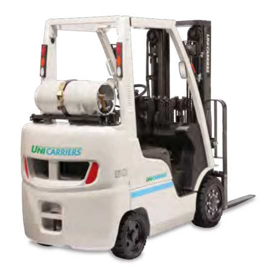
- Page 1 OPERATOR’S MANUAL MODELS 1F1/1F2 Platinum II Series Cushion & Pneumatic Tire Engine Powered/LPG, Gasoline, Dual Fuel, Diesel & Carburetor 3,000-8,000 lb. Capacities OPERATOR Printing: April 2018 (02) Publication No.: 997OE-45001 Printed in Marengo IL USA...
- Page 2 Reliability. It’s the defining trait of our company and our forklifts. UniCarriers’ roots extend back over 100 years, and over that time, strong, reliable performance has always been the hallmark of our organization, our people and our equipment. Today, our unrivaled reliability continues to provide UniCarriers’ customers with a competitive edge.
-
Page 3: Warnings
UNICARRIERS AMERICAS OPERATOR’S MANUAL MODEL 1F1/1F2 SERIES WARNING • This Original Instructions (Operator's) Manual contains important safety information and must be made available to the operator. • Keep this manual on the lift truck at all times. • Do not operate the lift truck unless you have reviewed and fully understand the Operator’s Manual. Failure to follow all of the instructions in this manual could be a violation of the Occupational Safety and Health Act. - Page 4 Failure to follow all instructions in this manual could be a violation of the Occupational Safety and Health Act. DISCLOSURE OF REGULATION APPLICABILITY FOR CALIFORNIA CUSTOMERS ONLY • To owner/operators of UniCarriers lift trucks in California: ARB Regulation 2449(d)(3) June 2008: Starting June 15, 2008 the California Air Resources Board (CARB) placed a limit in idling time for in use off road diesel powered equipment.
-
Page 5: A Word To Operators
UniCarriers your UniCarriers lift truck. We urge you to read this manual carefully Americas Corporation, hereafter referred to as UCA, reserves the right to familiarize yourself with the safety instructions before operating to make changes or improvements at any time without notice. -
Page 6: Lift Truck Modifications
Only in the event that UniCarriers Americas Corporation is no longer in business and there is no successor to the business, the user may arrange for a modification or alteration to a powered industrial forklift, provided however, that the user shall: a. -
Page 7: Table Of Contents
TABLE OF CONTENTS Traveling ................18 SUBJECT PAGE Loading ................. 20 Warnings ..................1 Dockboards (Bridge Plates), Trucks and Railroad Cars ..21 A Word to Operators ..............3 Surface and Capacity ............22 Lift Truck Modifications ............... 4 Fuel Handling ................ 23 Table of Contents ............... - Page 8 Applications ................36 Radiator Level Warning ............. 46 Application for UniCarriers Lift Trucks ........36 Air Cleaner Warning ............46 Prohibited Applications for UniCarriers Lift Trucks ....36 Fuel Filter Warning ............. 46 Main Components ..............37 Service Reminder Display ..........47 Meters, Indicators and Lamps ..........
- Page 9 Accelerator Pedal .............. 60 Suspension Seat Operator’s Weight Adjustment ....79 Cargo-Handling Control Levers ......... 60 Forward and Backward Control Lever ....... 79 Twin Control Lever Type ..........61 Backrest Inclination Adjustment ......... 79 Single Control Lever Type ..........61 Lumbar Adjustment ............
-
Page 10: Subject Page
TABLE OF CONTENTS Checking Air Cleaner ............109 SUBJECT PAGE Fuel Tank Cleaning: Drain Plug .......... 109 Engine Coolant Level ............94 Checking Fan Belt ............. 109 Refilling Engine Coolant ............. 94 Fuel Filter................109 Cooling System Bleeding Instructions........ 95 Air Purge ................ - Page 11 Servicing the Lift Truck in Storage........129 Post-Storage Servicing ............129 Options ..................131 Side Shift ................131 Sling Poing for Hook-On Type Side Shift ......131 Overview of Side Shift ............132 Main Terms used in this Section ........133 Safety Rules and Practices ..........
-
Page 12: Introduction
PLANNED MAINTENANCE manual describes the controls, their function and some special features which may be installed on this lift truck. UniCarriers lift trucks are built to A Periodic Planned Maintenance program is used in addition to work hard but not for misuse and/or abuse. -
Page 13: How To Use This Manual
HOW TO USE THIS MANUAL Included in this manual are the essentials of safe lift truck operation, The operating instructions in this guide do not replace any other rules truck features and functions and explanation of how to maintain your lift or laws of safety that are used in or required by federal, state, local truck. -
Page 14: Safety Signs And Safety Messages
SAFETY SIGNS AND SAFETY MESSAGES WARNING SYMBOLS AND LEVELS Safety signs and Safety messages are placed in this manual and on the Always follow the warnings in this Operator’s Manual and any located lift truck to provide instruction and identify specific areas where potential on the lift truck to help avoid accidents and/or injuries from occurring. -
Page 15: Safety Rules And Practices
SAFETY RULES AND PRACTICES SAFETY GUARDS OPERATOR QUALIFICATIONS WARNING WARNING • Operator must be trained, evaluated and authorized to drive • An overhead guard is intended to offer protection from falling the lift truck and must understand safety techniques and objects but cannot protect against every possible impact. -
Page 16: Personal Protective Equipment For Operating Lift Truck
PERSONAL PROTECTIVE EQUIPMENT FOR DAILY INSPECTION OPERATING LIFT TRUCK WARNING Helmet Safety Muffs • OSHA 1910.178 requires a daily or per shift inspection. Glasses Inspect the lift truck before operating. Do not operate the lift truck if it is in need of repair. If it is in need of repair, tag Dust the lift truck, remove the key (if equipped) and report the Mask... -
Page 17: Operator Responsibility
OPERATOR RESPONSIBILITY WARNING • Safe operation is the responsibility of the operator. • The operator shall develop safe working habits and also be aware of hazardous conditions in order to protect himself, other personnel, the truck, and material being handled. •... - Page 18 WARNING • A lift truck is unattended when the operator is more than 8 m (25 ft) from the truck which remains in view, or whenever the operator leaves the truck and it is not within view. • Before leaving the operator’s position: a.
-
Page 19: No Riders
NO RIDERS WARNING • Care shall be taken not to contact overhead installations such as lights, wiring, pipes, sprinkler systems, etc. WARNING • Do not sit on the forks or get under the forks or operator’s • A load backrest extension shall be used when necessary to platform at anytime whether empty or loaded. -
Page 20: Traveling
TRAVELING WARNING • Observe all traffic regulations including authorized plant speed limits. Under normal traffic conditions, keep to the right. Maintain a safe distance, based on speed of travel, from the lift truck ahead; and keep the lift truck under control at all times. - Page 21 WARNING • Under all travel conditions, operate the lift truck at a speed that will permit it to be brought to a stop in a safe manner. • Travel with load-engaging means or load at lowered height except during stacking operation. WARNING •...
-
Page 22: Loading
LOADING WARNING WARNING • Handle only stable and safely arranged loads. • Before driving over a dockboard or bridge plate, be sure that it is properly secured. Drive carefully and slowly across a. When handling off-center loads that cannot be centered, oper- the dockboard or bridge plate, and never exceed its rated ate with extra caution. -
Page 23: Dockboards (Bridge Plates), Trucks And Railroad Cars
DOCKBOARDS (BRIDGE PLATES), TRUCKS AND WARNING RAILROAD CARS • When attachments are used, extra care shall be taken in securing, manipulating, positioning, and transporting the load. Operate lift trucks equipped with attachments as partially loaded lift trucks when not handling a load. •... -
Page 24: Surface And Capacity
SURFACE AND CAPACITY WARNING WARNING • All types of dockboards shall have a high friction surface designed to reduce the possibility of employees or lift trucks • The Cushion Tire model lift trucks must be used on only slipping and shall be designed and maintained so that one smooth, solid floor conditions. -
Page 25: Fuel Handling
FUEL HANDLING WARNING • Do not breath exhaust gasses: they contain colorless and odorless carbon monoxide. Carbon monoxide is a dangerous gas and can cause unconsciousness or death. • Do not run the lift truck in closed spaces or poorly ventilated areas. -
Page 26: Installation Of Attachments
INSTALLATION OF ATTACHMENTS IN CASE OF TIP-OVER WARNING Lateral tip-over can occur if truck is improperly operated. • This lift truck has been designed for attachments (refer to Don’t risk injury or death. WARNING Buckle up belt Slow down before turning! "Lift Truck Modifications"... -
Page 27: Transporting Lift Truck
TRANSPORTING LIFT TRUCK APPROACH ANGLE, DEPARTURE ANGLE AND GANGWAY Refer to "Grade Clearance" on Main Truck Specifications. WARNING Ramp breakover angle Approach angle 1. Tilt the mast back to the maximum without load. 2. Check the approach and departure angles to make sure the underside of the lift truck does not come into contact with the load carrying platform or the ground. -
Page 28: Hoisting (Lifting) Up The Lift Truck
HOISTING (LIFTING) UP THE LIFT TRUCK WARNING WARNING • Make sure that the cables/wire ropes do not interfere with the overhead • Only use this method as a last resort to move the lift truck. If guard while lifting the lift truck. the normal application requires repeated lifting, a permanent lifting device/platform will be needed. -
Page 29: Function Tests
FUNCTION TESTS TRACTION BAR The functional tests are carried out to check whether the lift truck functions The traction bar should be used only correctly after it has been transported (over land or water), or after it has for pulling the out of ditches or lift truck been taken out of storage. -
Page 30: Position Of Data And Capacity Plates And Decals
POSITION OF DATA AND CAPACITY PLATES AND WARNING DECALS • It is not recommended to use another lift truck to tow or WARNING push a disabled lift truck. • In case the lift truck must be towed for repair, the ignition •... - Page 31 Except for EU region Lateral tip-over can occur if truck is improperly operated. Don’t risk injury or death. Buckle up belt WARNING Slow down before turning! Stay in seat IN CASE OF TIP-OVER Follow these Hold on DANGER Lean away Don’t jump! instructions: Brace feet...
-
Page 32: Data And Capacity Plates And Decals
DATA AND CAPACITY PLATES AND DECALS Actual Capacity will vary with lift truck configuration and load center. Mast configuration will determine the maximum lifting distance. These Know your lift truck. The data plate indicates all necessary values are stamped on the data plate. information regarding the type of attachments, lifting capacity, etc. -
Page 33: Identification Numbers
IDENTIFICATION NUMBERS The engine serial number is stamped as shown below. The serial number of the lift truck is stamped on the front panel. Gasoline Engine Gasoline Engine K21/K25, GK21/GK25 Carburetor K21/K25, GK21/GK25 EFI Engine No. Chassis serial number Diesel Engine QD32 Lift Truck Serial Number AP1F1 9T2XXXX... -
Page 34: Caution Drive Decal (In Case Of Tip-Over Decal)
CAUTION DRIVE DECAL (IN CASE OF TIP-OVER DECAL) WARNING DRIVE DECAL (TRAINED AND AUTHORIZED) WARNING Lateral tip-over can occur if truck is improperly operated. Don’t risk injury or death. WARNING Buckle up belt Slow down before turning! Stay in seat Do not operate this truck unless trained and authorized by your employer. -
Page 35: Pinch Point Decal
PINCH POINT DECAL MAST WARNING DECAL WARNING/AVERTISSEMENT ADVERTENCIA/AVISO WARNING • This decal instructs the operator to keep fingers away. Do not reach into the mast area. Personal injury may occur if any part of your body is between the moving and fixed WARNING sections of the mast. -
Page 36: Caution Drive Decal (Operation)
CAUTION DRIVE DECAL (OPERATION) RADIATOR WARNING DECAL WARNING NEVER OPEN WHEN HOT AVERTISSEMENT N’OUVREZ JAMAIS À CHAUD WARNING • Never remove the radiator cap when the engine is hot. Serious burns could be caused by high-pressure fluid escaping from the radiator. COOLING FAN WARNING DECAL WARNING WARNING... -
Page 37: Adj Lpg Warning Decal
ADJ LPG WARNING DECAL LPG FUEL WARNING DECAL WARNING • Do not operate the lift truck with the LPG cylinder (tank) overhanging the profile of the lift truck, damage to the WARNING cylinder (tank), serious injury or death may occur. •... -
Page 38: Operating Controls And Functions
APPLICATION FOR UNICARRIERS LIFT TRUCKS • Do not use as a towing truck for trailers UniCarriers lift trucks are solely designed and manufactured to • Not to be used for pushing applications handle goods. The lift truck should only be fitted with the appropriate accessories relevant to the application. -
Page 39: Main Components
MAIN COMPONENTS 1. Mast Upright: The mast upright is the lifting device for the forks. The lifting is done through hydraulic lift cylinders and chains. 2. Lift Cylinders: The cylinders are used to lift the forks up and down. 3. Operator Compartment: This compartment houses the (a) ignition switch, (b) horn button, (c) lighting and turn signal switch, (d) fuel- change switch (Dual Fuel forklift), (e) seat belt interlock or shutdown indicator (red-option), (f) maximum speed change switch (option),... -
Page 40: Meters, Indicators And Lamps
METERS, INDICATORS AND LAMPS 10. Meter Display (see note below) 11. Water Temperature Gauge The operator compartment contains the main functional controls to 12. Fuel Gauge (not applicable) operate the lift truck in a safe and controlled manner. The meter panel 13. -
Page 41: Multipurpose Warning Light
! MULTIPURPOSE WARNING LIGHT OIL PRESSURE WARNING LIGHT This warning illuminates when one of the LCD warning symbols This warning illuminates when the oil pressure is low. illuminates. It also illuminates when the water temperature is high or the CAUTION fuel level is low. -
Page 42: 10. Meter Display
10. METER DISPLAY Changing Meter Display Changes automatically Start display (Appears immediately by more than 4.0 km/h (2.5 MPH) after the ignition switch is turned on.) Normal display (time display) Speedometer display lift truck speed Changes automatically. km/h Press * MPH display is also available. Press Press Press... -
Page 43: Clock
Setting the Time METER DISPLAY NOTE: • The display time and date will be reset if the battery cable is disconnected or the battery is replaced. If the display has been reset, set the time and date again. Press and hold Number change mode Clock... -
Page 44: Date
Date Setting the Date H '05/02/31 Press and hold ’05/02/31 ’06/02/31 ’06/06/31 ’06/06/26 ’06/06/26 H '05/02/31 ’06/02/31 ’06/06/31 ’06/06/26 ’06/06/26 ’06/06/26 ’06/06/26 Setting completed Press the button on the normal display (clock) to change from the time display to the date display. Press the button again to return to Press the button to change the setting item from yearmonth... -
Page 45: Hour Meter
Hour Meter Indicates the current water temperature in levels 0 - 4. The buttons can be used to Temp. Indication Level When level 2 is indicated, the change from the normal display Level 4 High coolant temperature is correct. (clock) to the hour meter Level 3 When the indication reaches display. -
Page 46: 12. Fuel Gauge
12. FUEL GAUGE 13. TRANSMISSION POSITION Indicates the current fuel level Fuel Indication Level in levels 0 - 5. When level 5 is When the transmission position indicator displays the “F” position and Level 5 Full indicated, the fuel tank is full. the transmission has shifted, the display appears as shown here. -
Page 47: Malfunction And Warning Indications
"2F" position, the displays appears as shown here. NOTE: MAST INTERLOCK WARNING UniCarriers does not recommend starting the lift truck from the second This warning illuminates when the ignition switch is turned on and the speed position. operator is not seated on the seat or the operator leaves the seat for three (3) seconds or more. -
Page 48: Lpg Level Warning/Lpg Rack Lock Warning
• Check the level of automatic transmission fluid (refer to page 97). LPG LEVEL WARNING/LPG RACK LOCK WARNING (LPG • If the warning light illuminates even though the transmission fluid is AND DUAL FUEL LIFT TRUCKS) at normal level, contact your Local Authorized Dealer for inspection. This warning illuminates when the LPG level is low. -
Page 49: Service Reminder Display
SERVICE REMINDER DISPLAY DISPLAYS WHEN MALFUNCTION OCCURS Error code MAINTE E-03 PERIOD When the time for regular service inspection (planned maintenance) approaches, this warning illuminates for fifteen (15) seconds after ignition switch is turned on. This does not affect driving. E-03 VCM COMM ERR When the display shown above appears, contact your Local Authorized... -
Page 50: Driver Recognition Mode
DRIVER RECOGNITION MODE Registering a password can restrict the When the ignition switch is off drivers of the lift truck. You can register a password for up to 5 people (A to E). When the ignition switch is on Contact your Local Authorized Dealer for information about the registration of the Select the alphabet letter (A, B, C, D, E) for the password password. -
Page 51: Lpg Remaining Time Management
LPG REMAINING TIME MANAGEMENT CAUTION • Set a time that leaves a sufficient amount of leeway. • After replacing the LPG Cylinder (tank), be sure to set the time setting again. Otherwise, the time setting continues 00.0 after LPG Cylinder (tank) replacement, and this may result in the LPG level warning symbol turning on at an unintended time. - Page 52 Following is an explanation of how to set the time setting for the first time. Example: Setting the time to 12.3 hours Press and hold 00.0 Press the button to change the number up. Press the button to change the number down. Press the button to confirm the number for each digit.
- Page 53 Following is an explanation of how to set the time setting for the second and later times. Example 1: Changing the time from 12.3 hours (previous setting) to 6.5 hours Example 12: Using the same 12.3 hours setting (previous setting) again Operation when using the previous time setting again 12.3 Setting completed...
-
Page 54: Switches
SWITCHES HORN BUTTON Pushing the button in the center of the steering wheel will sound the 1. Horn button horn, regardless of ignition switch position. 2. Ignition switch NOTE: 3. Lighting switch and Turn signal switch For forklifts with the optional joystick control, there is also a horn button NOTE: located on the joystick control. -
Page 55: Ignition Switch
IGNITION SWITCH Diesel Lift Trucks Do not operate the starter for more than thrity (30) consecutive Turn the key or lever (option) on the seconds. If the engine does not start wait for at least thrity (30) seconds ignition switch to start or stop the engine. START and then try again, starting with preheating. -
Page 56: Lighting Switch And Turn Signal Switch
LIGHTING SWITCH AND TURN SIGNAL SWITCH FUEL CHANGE SWITCH (DUAL FUEL LIFT TRUCKS) Lighting Switch This switch is used to switch fuel from LPG to gasoline or vice versa. Position bar To turn on one of the lamps in the table, LPG Position: Press to this position to turn this switch to align the position bar (–) LPG position... -
Page 57: Seat Belt Interlock Or Shutdown Indicator (Red-Option)
SEAT BELT INTERLOCK OR SHUTDOWN INDICATOR (RED - MAXIMUM SPEED CHANGE SWITCH (OPTION) OPTION) This switch is an optional setting This option is an interlock system that will switch for electronic control POWER (power mode) not let you start the lift truck without the gasoline, LPG and dual fuel lift operator being in the seat with the seat belt trucks. -
Page 58: Throttle Sensitivity Adjust Switch (Option)
THROTTLE SENSITIVITY ADJUST SWITCH (OPTION) TRANSMISSION SHIFT (SMOOTHSHIFT) INDICATOR (GREEN - OPTION) This switch is an optional setting The transmission will not shift switch for electronic control POWER (power mode) direction at high travel speeds or gasoline, LPG and dual fuel lift engine RPM's. -
Page 59: Operating Controls
OPERATING CONTROLS SELECTOR LEVER This lever is used to change the 1. Selector lever 1 Speed driving direction of the lift truck NOTE: (forward or reverse). Push the lever For forklifts with the optional joystick control, this switch is located on forward (up) away from you to drive the left side. -
Page 60: Parking Brake Lever
PARKING BRAKE LEVER CAUTION To set the parking brake, fully pull Release Parking position position the lever towards you. To release the • Always depress the brake pedal before operating the Button parking brake, push down the button selector lever. on top of the lever and then push the •... -
Page 61: Inching Brake Pedal
INCHING BRAKE PEDAL WARNING The inching brake pedal allows you to finely adjust the forward and reverse driving speed. • During deceleration on any grade, only use the brake pedal or increase or decrease the speed by using the accelerator The transmission internal clutch pedal. -
Page 62: Accelerator Pedal
ACCELERATOR PEDAL • Operating the control lever without properly sitting in the operator's seat with the seat belt fastened causes the This pedal allows you to adjust the loading interlock warning light to blink and the loading engine speed (RPM's). The engine mechanism to be inactive. -
Page 63: Twin Control Lever Type
Twin Control Lever Type Control of forward and backward tilting speeds: For both forward and backward tilts, the speed can be changed by controlling the tilt angle This method uses two levers: a lift lever for of the lever and by how much the operator depresses the accelerator moving the fork up and down and a tilt lever pedal. -
Page 64: Joystick Control Lever (Option)
NOTE: WARNING • Before the ignition switch is turned ON, make sure that the joystick lever is set to the neutral position. If the lever is placed in any • Do not perform forward tilt while the lift truck is traveling. It position other than the neutral position, cargo handling or fork may cause loads to shift or drop and also may cause the lift operation cannot be performed. - Page 65 Speed Control: Control of lifting and lowering speeds: For both lifting and lowering, the speed can be changed by controlling the tilt angle of the lever. Emergency Stop Button Control of forward and backward tilting speeds: For both forward and backward tilts, the speed can be changed by controlling the tilt angle of the lever.
-
Page 66: Tilt Horizontal Switch (Option)
Tilt-Horizontal Switch (Option) NOTE: • In case of twin lever method, the tilt-horizontal switch is attached to When forward tilt is performed with the Tilt-Horizontal the tilt lever. mast tilted backward, the forward tilt Switch operation can automatically be stopped •... -
Page 67: Ansi/Itsdf Standards For Lift Truck Clamp Attachments
ANSI/ITSDF STANDARDS FOR LIFT TRUCK CLAMP ATTACHMENTS The ANSI/ITSDF Standards regarding lift trucks mounted clamp attachments took effect for lift trucks shipped on or after October 7, 2010. This current standard affects lift trucks equipped with a load bearing clamp (paper roll clamp, carton clamp, etc.) and requires the operator to perform two distinct motions before opening (releasing) the clamp. -
Page 68: Operating The Lift Truck
OPERATING THE LIFT TRUCK The following are the recommended procedures that should be PRECAUTIONS FOR COLD AND HOT WEATHER followed before and while operating a UniCarriers lift truck. IN COLD WEATHER Since the Occupational Safety and Health Act (OSHA) • Oil and Grease 29CFR1910.178(I) requires that “only trained and authorized... -
Page 69: Operational Procedures
OPERATIONAL PROCEDURES WARNING There are certain hazards that cannot be avoided solely by mechanical means in the everyday use of lift trucks. Only the intelligence, good • Do not turn the ignition switch ON unless the selector lever sense, and care of the operator, along with proper maintenance, will is in neutral. - Page 70 Follow the procedure outlined below to start the engine. • If the engine fails to start within ten (10) seconds, release the ignition switch and wait for ten (10) seconds before attempting to Dual fuel lift trucks have a fuel change switch. Use this switch to select start the engine.
-
Page 71: Fuel-Change Switch
FUEL-CHANGE SWITCH (DUAL FUEL LIFT TRUCKS) 8. Check the lift/lower/tilt functions. Report any malfunctions. WARNING WARNING • Do not operate (turn on or open) the LPG cylinder (tank) • Always perform operational checks in a clear area. change (refill) valve. Opening the valve may cause LPG to 9. -
Page 72: To Change From Lpg To Gasoline Operation
• With the fuel-change switch set in the neutral position the engine TO CHANGE FROM GASOLINE TO LPG OPERATION: cannot be started. Before starting the engine always change the 1. Press the fuel-change switch from the GAS to the neutral position. switch to LPG or GAS. -
Page 73: Diesel Lift Truck Starting
3. After completion of operation completely close the discharge valve. 3. Keep the ignition switch in the ON position until the glow pilot light turns off. This indicates that preheating is complete. NOTE: NOTE: After operation, if the lift truck is not used for several hours or more, or during cold weather seasons, park the lift truck with the fuel-change Engine preheating is controlled automatically corresponding to the switch positioned on the gasoline side. - Page 74 • When it is not necessary to preheat the engine because of high WARNING engine coolant temperature immediately after it stops or for some other reason, the engine can be started by turning the ignition • Avoid quick steering or acceleration as this may cause an switch to the START position before the glow plug indicator light accident, which could result in serious injury or death.
-
Page 75: Procedure For Jump Starting Efi Engines
PROCEDURE FOR JUMP STARTING EFI ENGINES CAUTION WARNING • Always connect battery positive (+) to positive (+) post and battery negative (-) to negative (-) post in the jump start • Always follow the instructions below. Failure to do so could access box. - Page 76 Optional Block Heater Plug WARNING 110 Volt Only (refer to page 73) • This plug is for the block heater and should only be • If done incorrectly, jump starting can lead to a battery connected to 110 volt power. explosion, resulting in severe injury or death.
-
Page 77: Automatic Transmission
AUTOMATIC TRANSMISSION Starting the lift truck from the stopped condition: 1. When the selector lever is in the neutral position: • The lift truck will not move even if the accelerator pedal is depressed. Forward 2. When the selector lever is in the F or R position: •... - Page 78 • If the lift truck is equipped with Travel Speed Control, the truck reverse travel speed will be reduced to 3 mph when the forks are UniCarriers does not recommend starting the lift truck from the second less than five (5) inches off the ground.
-
Page 79: Loading
LOADING CLIMBING Adjust distance between the forks so that they are at or near the same For safety reasons, when driving a loaded lift truck up a steep grade, distance to the centerline of the lift truck. The wider the interval between it must be driven forward with the load in front;... -
Page 80: Stopping And Parking The Lift Truck
STOPPING AND PARKING THE LIFT TRUCK FORKS 1. Park the lift truck in designated parking areas only. The fork-to-fork distance can be properly adjusted by unlocking 2. Make sure the lift truck does not block fire aisles, fire equipment, the lock pins on the forks. These stairways or walkways. -
Page 81: Seat Adjustment
SEAT ADJUSTMENT BACKREST INCLINATION ADJUSTMENT To adjust the backrest to the SUSPENSION SEAT OPERATOR’S WEIGHT ADJUSTMENT desired angle pull up and hold To adjust the suspension seat to the lever or strap on the left side the operator’s weight pull out the of the seat. -
Page 82: Lumbar Adjustment
SEAT BELT LUMBAR ADJUSTMENT To expand the upper lumbar 1. Holding the tongue pull out the turn the knob clockwise (refer seat belt gently. to L1 position). To expand the 2. Wrap the lower part of the lower lumbar turn the knob Tongue hipbone with the seat belt as counter-clockwise (refer to... - Page 83 • For cleaning the seat belt, use a neutral detergent or WARNING lukewarm water. After cleaning, dry it completely before use. Be sure not to use an organic solvent such as benzine • Periodically check to see that the seat belt and metal or gasoline, otherwise the seat belt deteriorates in its components, such as buckles, tongues, retractors, performance and may not function as designed.
-
Page 84: Seat Belt Interlock Options
SEAT BELT INTERLOCK OPTIONS Option 4 - Seat Belt / Transmission, Mast and Engine Starter Interlock with Engine Shutdown The lift truck may be equipped with one of four options which requires the operator to be seated with the seat belt fastened prior to primary If the seat belt is unfastened the engine starter cannot be engaged, or functionalty being enabled. -
Page 85: Top Panel
TOP PANEL 4. Pull up on the lock lever in the front left side of the top panel to unlock it while pressing down, then lift the panel rearward. WARNING • Do not open the top panel (hood) with the engine running. Do Lock lever not place hands near the cooling fan because it rotates at a high speed and may cause injury. -
Page 86: Close Operation
CLOSE OPERATION WARNING 1. Make sure the steering wheel is tilted upward. • Before adjusting the steering wheel, turn the ignition switch 2. Since there is reaction of the gas stay, press down on the front top off and set the parking brake. portion of the hood (top panel) until it is securely locked in place. -
Page 87: Radiator Cover
RADIATOR COVER REARVIEW MIRROR (OPTION) The radiator cover can be Adjust the rearview mirror(s) by hand so that you ensure the best view removed with the top panel to the rear. closed. For inspection of the radiator Rearview mirror or replenishment of the engine coolant, loosen the right and left bolts by hand. -
Page 88: Lpg Cylinder (Tank) Holder
LPG CYLINDER (TANK) HOLDER CLOSE PROCEDURE Before closing the LPG Cylinder (tank) holder, make sure that the top panel is properly closed (refer to page 84). 1. Pull the lock pin up to unlock the LPG Cylinder (tank) holder. Slowly close the LPG Cylinder (tank) holder and make sure that the latch pin is in the locked position. -
Page 89: General Care And Maintenance
GENERAL CARE AND MAINTENANCE WET CELL BATTERY CARE AND MAINTENANCE WARNING The following is general information regarding the best methods for • Only trained and authorized personnel should conduct using and maintaining the battery and it not intended to address details maintenance or servicing of this lift truck and its battery. -
Page 90: Battery Fluid Level
BATTERY FLUID LEVEL WARNING • Do not place tools or other metallic objects on the top surface of the battery where they may come in contact with Proper area the battery terminals and cause an electrical short. This electrical short may cause sparking. The sparking may ignite the hydrogen gas escaping from the battery resulting in a serious explosion. -
Page 91: Battery Specific Gravity
BATTERY SPECIFIC GRAVITY DAILY INSPECTION To maintain your lift truck in proper condition and ready for safe operation, be sure to perform the daily checks indicated below. If you 1.30 note any malfunction notify your Local Authorized Dealer. 1.28 1. Check battery fluid level. 2. - Page 92 11. Check for full motion and proper function of all the steering and 25. Check and verify capacity plates and decals are legible, if not travel controls. replace. 12. Check steering wheel play. WARNING 13. Check that all guards, horn, lights, limit switches, warning and safety devices, indicators, etc.
-
Page 93: Operator's Daily Checklist (Sample)
OPERATOR'S DAILY CHECKLIST (SAMPLE) WARNING • Carry out the daily checks as per “Daily Inspection” in this Operator’s Manual on page 73 and the applicable provisions of laws and regulations of your country (In U.S. OSHA 29CFR1910.178). I.T.A. Class IV and V Operator’s Daily Checklist and Safety Inspection (sample) Check each of the following items before the start of each shift. -
Page 94: Maintenance And Inspection
MAINTENANCE AND INSPECTION Gasoline to be used • Except Germany: Regular (Unleaded) FUEL RECOMMENDATION • Germany: Normal gasoline leaded DIN 51 600 or normal unleaded DIN 51 607. Label of fuel type CAUTION Close Open • Be careful not to allow water or debris to enter the fuel tank during refilling, as it may cause damage to the EFI fuel system components. -
Page 95: Engine Oil Level
ENGINE OIL LEVEL REFILLING ENGINE OIL 1. For refilling the engine oil tank with engine oil, remove the oil filler QD32 K21/ K25, GK21/GK25 Proper area cap and slowly pour genuine OEM motor oil into the tank while Proper area High checking the oil level with the oil level gauge until the oil reaches the specified oil level. -
Page 96: Engine Coolant Level
ENGINE COOLANT LEVEL REFILLING ENGINE COOLANT Visually check the amount of 1. Remove the reservoir tank filler cap and add coolant until the "MAX" coolant in the reservoir tank level is reached (refer to page 95 for proper mixing ratio). when the engine is cold. -
Page 97: Cooling System Bleeding Instructions
COOLING SYSTEM BLEEDING INSTRUCTIONS 1. Remove the radiator cover and open the engine hood. Remove the radiator cap. Antifreeze 2. Place an appropriate size container under the radiator. Open the Applicable Capacity LLC Density drain cock of the radiator and extract the coolant. Engine (US gal, Imp gal) 3. -
Page 98: Brake Fluid Level
8. Add the recommended engine coolant mixture into the radiator, WARNING when the coolant comes out of the bleeder hole with no air bubbles install the bleeder screw and tighten to 6.3 - 8.0 Nm (55.7 - 75.8 • If brake fluid is unusually low, a leak or stain is detected, in/lb) of torque. -
Page 99: Automatic Transmission Fluid Level
AUTOMATIC TRANSMISSION FLUID LEVEL REFILLING AUTOMATIC TRANSMISSION FLUID Automatic transmission fluid can be added through the level gauge hole. Checking the fluid level with the level gauge, pour OEM fluid into the level gauge hole until the fluid level is in the proper range (refer to page 128). -
Page 100: Hydraulic Oil Level
HYDRAULIC OIL LEVEL REFILLING HYDRAULIC OIL 1. Check the oil level in the hydraulic oil tank. Remove the hydraulic oil filler cap. While checking the hydraulic oil level with the level gauge, pour the specified hydraulic oil into the oil filler until NOTE: the oil level is in the proper area (refer to page 128). -
Page 101: Wheel And Tire
WHEEL AND TIRE • If the tire pressure is not correct it can affect the stability of the lift truck, potentially resulting in a tip-over. It can also cause rupturing, premature tire wear or explosive separation of the multi-piece rim set. •... - Page 102 1F2 2.8-3.0 Ton (Pneumatic) 28x9-15/12PR 102 (7.0, 700) 1F2 3.5 Ton (Pneumatic) 250-15/16PR 102 (7.0, 700) WARNING 1F1 (Compact Pneumatic) 6.00-9/12PR 145 (10.0, 1000) • *Only use the OEM recommended HiLoad steer tire as 1F2 (Compact Pneumatic) 21x8-9/14PR 128 (9.0, 900) listed in the parts catalog.
-
Page 103: Tire Replacement
TIRE REPLACEMENT • Use hardwood blocks that do not slip easily and are strong enough to withstand the lift truck weight. Do not use broken WARNING or cracked blocks or metal blocks that slip easily. • Use wood blocks of the following size: •... -
Page 104: Front (Drive) Tire
Front (Drive) Tire: CAUTION 1. Place the lift truck on a level and solid surface. • When removing the tire from the wheel rim, do not remove 2. Start the engine and raise the carriage about 250 mm (9.84 in). the rim set bolts and wheel nuts before releasing the air 3. -
Page 105: Rear (Steer) Tire
1. Place the lift truck on a level and solid surface. CAUTION 2. Apply the parking brake and place chocks behind the front wheels to prevent movement of the lift truck. • For replacement of the double tires, do not install the tires in the incorrect direction of the inner and outer rim. - Page 106 4. Cushion: Loosen the retainer nut 6. Pneumatic: Remove the wheel nuts and the rear tire. Install one or two turns each by turning it replacement tire. counterclockwise. 6. Cushion: Remove the retainer nut and the rear tire. Install replacement tire. WARNING •...
- Page 107 Tightening torque: Unit: ft-lb (N-m) Model P1F1 P1F2 A1F1 A1F2 2.0-2.5 ton 2.8-3.0 ton 3.5 ton 123 - 166 181 - 217 325 - 434 325 - 434 123 - 166 145 - 181 Single tire (167 - 226) (245 - 294) (441 - 588) (441 - 588) (167 - 226)
-
Page 108: Checking Mast
CHECKING MAST CHECKING LIFT CHAIN Check the mast to ensure that: WARNING a. No oil leakage occurs at or around the lift and tilt cylinders. b. Check rollers for proper rotation. • Use extreme care when checking lift chain tension. c. -
Page 109: Fork Inspection
FORK INSPECTION FORK REPAIR Ensure the forks are secured in their proper position and they are not Repair - Only the manufacturer of the fork or an expert of equal damaged. competence shall decide if a fork may be repaired for continued use, and the repairs shall only be carried out by such parties. -
Page 110: Checking Horn
CHECKING HORN CHECKING PARKING BRAKE LEVER Check the horn for proper operation. Make sure the parking brake works properly when pulled and then returns to its original CHECKING LIGHTS (release) position. Mark sure that lights illuminate when switches are placed into the ON Pulling force at gripping position is 116 - position. -
Page 111: Checking Air Cleaner
CHECKING AIR CLEANER CHECKING FAN BELT Fan belt Remove the three clamps securing Check the belt deflection by Clamp the air cleaner case and take the applying moderate thumb pressure element out carefully. Clean the Element at a point midway between the Deflection amount element by tapping it by hand or... -
Page 112: Air Purge
AIR PURGE (DIESEL LIFT TRUCKS) CAUTION WARNING • Parts may remain very hot immediately after the engine has stopped. Wear protective gloves and perform the operation • Never allow open flames, smoking or other sources of carefully so as not to touch possible hot parts around the ignition in the operation area. -
Page 113: Draining Of Tar From The Vaporizer
DRAINING OF TAR FROM THE VAPORIZER 6. For the bolt type, slowly remove the plug. For the optional drain valve, open the CAUTION vaporizer drain valve lever. 7. Tar will drip, when it stops fix the bolt or • This should only be done by a trained and authorized person. close the vaporizer drain valve lever, the The vaporizer is an apparatus used during LPG operation to control procedure is complete. -
Page 114: Precautions For Using Lpg
PRECAUTIONS FOR USING LPG • Change only in well ventilated areas. • Do not use or park near fire. • Do not expose directly to the sun for extended periods of time. • Inspect equipment pipe connections for gas leaks at mating sections. -
Page 115: Cylinder (Tank) Size
CYLINDER (TANK) SIZE Vehicle Classification Weight Filled Weight Empty Diameter Length Cylinder Size 1 ton series 38 lb 33 lb 12 in 27-1/4 in 2 - 3 ton series 38 lb 33 lb 12 in 27-1/4 in Pneumatic 2.5 ton and up 70 lb 43 lb 12 in... -
Page 116: Lpg Cylinder (Tank) Replacement
LPG CYLINDER (TANK) REPLACEMENT Removing Cylinder (Tank) Swing-Out Type WARNING 1. Place the fuel-change switch in the LPG position. • Replace the cylinder (tank) in a well ventilated area. 2. Turn the discharge valve, located on the right side • While replacing the cylinder (tank), never use or get close to when viewed from the rear fire. -
Page 117: Installing Cylinder (Tank) Swing-Out Type
Installing Cylinder (Tank) Swing-Out Type WARNING 1. Turn the LPG Cylinder (tank) so that the side with the locator hole • Do not attempt to replace the LPG Cylinder (tank) with the for the locator pin on the bracket are lined up. Securely grasp the holder in the open position. -
Page 118: Removing Cylinder (Tank) Swing-Down Type
4. Slowly open the discharge valve by turning counterclockwise. If Removing Cylinder (Tank) Swing-Down Type opened to fast the LP flow will stop. To correct, close the valve and 1. Follow steps 1 through 7 in wait five (5) seconds, then slowly open again. removing cylinder swing-out WARNING type (refer to page 114). -
Page 119: Removing Cylinder (Tank) Fixed Type
2. Follow steps 2 through 4 in installing cylinder swing-out type (refer REFILLING LPG CYLINDERS (TANKS) to page 115-116). WARNING 3. While supporting the bottom of the LPG cylinder, slowly push the holder up until it is in a horizontal position. •... -
Page 120: Periodic Maintenance And Lubrication Schedule
PERIODIC MAINTENANCE AND LUBRICATION SCHEDULE Before delivery of your new lift truck, your dealer provides a pre-delivery inspection and adjustment service specified by the factory and designed to ensure satisfactory performance. The following tables list the servicing required to keep your lift truck operating in good mechanical condition. The lift truck should be attended to as indicated, preferably by your Local Authorized Dealer. - Page 121 Interval Months How to Inspection Items check Hundreds of hours Battery: mounting, level and specific gravity Visual/Test Harness and connectors Visual Fuses If Necessary Visual Relays Visual Switches Test Lights (all) Test Horn/Buzzer Test Gauge and indicators Test Bulbs If Necessary Visual Oil level Visual...
- Page 122 Interval Months How to Inspection items check Hundreds of hours Wheel bearing for looseness Test/Adjust Wheel bearing grease (repack) Replace Wheel bearing for looseness Test/Adjust Steer axle adjustment If Necessary Adjust Wheel play Test Wheel bearing grease (repack) Replace Kingpin Grease Wheel nuts Test/Torque...
- Page 123 Interval Months How to Inspection items check Hundreds of hours Wheel operation effort Test Steering fluid pressure If Necessary Test Steering wheel (movement and play) Test Function of brake system Test Brake fluid level Replace Brake pedal Test/Adjust Brake lining wear Visual Shoe clearance adjustment Adjust...
- Page 124 Interval Months How to Inspection items Check Hundreds of hours Hydraulic pressure If Necessary Test Hydraulic oil level Visual Hydraulic oil replacement Replace Micron oil filter Replace Suction filter Clean Movement and connection of levers Test Hydraulic hoses and tubes (cracks, damage Visual and fittings) Lift and tilt cylinder mounting and operation...
- Page 125 Interval Months How to Inspection items Check Hundreds of hours Function of mast Test Mast system (damage/cracks/wear) Visual Clearance of each stage If Necessary Measure Mast rail Grease Mast/carriage rollers If Necessary Visual/Test Back up metals Grease Thrust metals Grease Lift chains wear/tension Visual/Adjust Attachments mounting...
-
Page 126: Periodic Maintenance And Lubrication Schedule For Emission Control System
PERIODIC MAINTENANCE AND LUBRICATION SCHEDULE FOR EMISSION CONTROL SYSTEM Before delivery of your new lift truck, your dealer provides a pre-delivery inspection and adjustment service specified by the factory and designed to ensure satisfactory performance. The following tables list the servicing required to keep your lift truck operating in good mechanical condition. The lift truck should be attended to as indicated, preferably by your Local Authorized Dealer. - Page 127 Interval Months Inspection items How to Check Hundreds of hours Intake and exhaust valve clearance Test/Adjust (operating temp) Drive belt tension Visual Engine oil Replace Oil filter Replace Engine Coolant (LLC) Replace Air cleaner element Visual/Replace Spark plugs Visual PCV valve Replace Piping or pipe connector portion for Visual...
- Page 128 Interval Months How to Inspection items Check Hundreds of hours Intake & exhaust valve clearance Adjust (operating temp) Drive belt tension Visual Engine oil Replace Oil filter Replace Engine Coolant (LLC) Replace Air cleaner element Visual/ Replace Water Separator Drain Engine idle rpm Adjust Nozzle...
-
Page 129: Lubrication Chart
LUBRICATION CHART Lubricate/Inspect ( stands for "Lubricate at symmetrical positions) Suitable Oil Change Item Below Above ( stands for "Change at symmetrical positions) 16°C (60°F) 16°C (60°F) Gasoline Engine Oil Refer to Page 128 Every 12 Months (2,400 hours) ... -
Page 130: Recommended Lubricants
RECOMMENDED LUBRICANTS RECOMMENDED SAE VISCOSITY CHART System/Component Oil and Grease Remarks GASOLINE ENGINE OIL Gasoline API SJ or SL Refer to 20W-20, 20W-40, 20W-50 Engine Oil 15W-50 Diesel API CF Recommended SAE 10W-30, 10W-40, 10W-50 Viscosity Chart Gear Oil Differential API GL-4 or 5 * Not recommended 5W-30... -
Page 131: Putting Lift Truck In Storage
PUTTING LIFT TRUCK IN STORAGE PRE-STORAGE SERVICING 1. Lubricate the lift truck (refer to page 127). Change the oil and coat Putting the lift truck in storage includes both storing the truck at the end all exposed areas of hydraulic cylinders with corrosion resistant of each working day or storing the truck over a long period of time. - Page 132 3. Check the battery specific gravity. Fully charge the battery. Be sure to completely charge the battery before putting it back on the lift truck. When connecting the battery cables, make sure that the positive and negative terminals are connected correctly. 4.
-
Page 133: Options
OPTIONS SIDE SHIFT SLING POINT FOR HOOK-ON TYPE SIDE SHIFT Sling point This illustration shows the sling point of the hook-on type side shift attachment which is used for installation and removal. -
Page 134: Overview Of Side Shift
For handling (safety, operations, The following is the standard amount of side shift. inspection) of the lift truck, refer to the applicable sections of this manual. Model Variation Side Shift Distance 1F1/1F2 series Each to right/left 100 mm (3.94 in) -
Page 135: Main Terms Used In This Section
SAFETY RULES AND PRACTICES WARNING • Do not make sudden and quick shifts with the forks loaded or raised. Shift to right. Shift to left. MAIN TERMS USED IN THIS SECTION Shift: To move the forks or load to the right or the left. Side Shift Stroke: The maximum distance the forks or load can travel to the right or the left. - Page 136 WARNING WARNING • Do not use the shift function to push or pull loads or pallets. • Do not travel with unstable or unsecured loads. If you use the side shift to pull or push loads, the equipment can be Do not travel with loads shifted to one side.
-
Page 137: Operation Of The Control Lever For The Side Shift
OPERATION OF THE CONTROL LEVER FOR THE SIDE SHIFT When the lever is pulled toward the operator, the shift finger bar (with forks A lift truck attached with a side shift has a control lever to operate the mounted) shifts (moves) to the right. side shift, in addition to the control levers for standard operations. -
Page 138: Side Shift Operation
SIDE SHIFT OPERATION CAUTION 1. Pallet • Do not shift the forks while the forks are inserted into the 2. Fork pallet. This could cause the load to shift if the pallet is 3. Deviation pushed. 4. Center of forks •... -
Page 139: Daily Checks And Simple Maintenance
DAILY CHECKS AND SIMPLE MAINTENANCE WARNING • If any abnormality is noted in the daily checks, immediately report it to the appropriate personnel or contact your Local Authorized Dealer for repair. Do not operate the lift truck until the malfunctions is repaired. •... -
Page 140: Specifications
36: 3.6 ton / 600 mm, 8,000 lb / 24 in TRANSMISSION A: 1 Speed Automatic F: 2 Speed Automatic BASE MODEL 1F1: 1 Ton Series 1F2: 2 Ton Series WHEEL BASE (1F2 SERIES) : Standard G: Long J: Intermediate... -
Page 141: Main Truck
MAIN TRUCK - 1F1 (PNEUMATIC) BASED ON 2W330 MAST, 1070MM FORKS AND MINIMUM BATTERY SPECIFICATIONS Model code MP1F1A15JV/ MP1F1A18JV/ MP1F1A20JV/ MP1F1A15U/WU MP1F1A18U/WU LV/DV LV/DV LV/DV Item Rated Load Capacity lb (kg) Refer to Truck Data Plate Load center in (mm) - Page 142 Model code MP1F1A15JV/ MP1F1A18JV/ MP1F1A20JV/ MP1F1A15U/WU MP1F1A18U/WU LV/DV LV/DV LV/DV Item Approach Angle 37.0 Ramp Breakover Grade Clearance 49.0 Angle Departure Angle 39.0 37.0 35.0 39.0 37.0 Full Load fpm (mm/sec) 122.0 (620) 112.2 (570) Empty fpm (mm/sec) 127.9 (650) Full Load fpm (mm/sec) 108.2 (550)
- Page 143 Model code MP1F1A15JV/ MP1F1A18JV/ MP1F1A20JV/ MP1F1A15U/WU MP1F1A18U/WU LV/DV LV/DV LV/DV Item Forward mph (km/h) 11.5 (18.5) Maximum Travel Speed Reverse mph (km/h) 11.5 (18.5) 3912 (1774 / 3889 (1764 / Drawbar Pull Maximum Full Load lb (kg / N) 3705 (1680 / 16450) 17400) 17300) Truck Weight...
- Page 144 MAIN TRUCK - 1F2 (PNEUMATIC) BASED ON 2W330 MAST, 1070MM FORKS AND MINIMUM BATTERY SPECIFICATIONS Model code MP1F2A20JV/ MU1F2A20JV/ MY1F2A20V/U MP1F2A20U/WU MU1F2A20U/WU LV/DV LV/DV Item Rated Load Capacity lb (kg) Refer to Truck Data Plate Load center in (mm) 24 (600) Overall Length (to face of forks) in (mm) 96.9 (2460)
- Page 145 Model code MP1F2A20JV/ MU1F2A20JV/ MY1F2A20V/U MP1F2A20U/WU MU1F2A20U/WU LV/DV LV/DV Item Approach Angle 32.0 Ramp Breakover Grade Clearance 44.0 Angle Departure Angle 45.0 Full Load fpm (mm/sec) 118.1 (600) 129.9 (660) 127.9 (650) 104.3 (530) 108.3 (550) Empty fpm (mm/sec) 127.9 (650) 137.8 (700) 135.8 (690) 127.9 (650)
- Page 146 Model code MP1F2A20JV/ MU1F2A20JV/ MY1F2A20V/U MP1F2A20U/WU MU1F2A20U/WU LV/DV LV/DV Item Forward mph (km/h) 11.8 (19.0) 11.2 (18.0) Maximum Travel Speed Reverse mph (km/h) 11.8 (19.0) 11.2 (18.0) 3880 (1760 / 4189 (1900 / 4542 (2060 / 3957 (1795 / 4696 (2130 / Drawbar Pull Maximum Full Load lb (kg / N)
- Page 147 Model code MP1F2A25JV/ MU1F2A25JV/ MY1F2A25V/U MP1F2A25U/WU MU1F2A25U/WU LV/DV LV/DV Item Rated Load Capacity lb (kg) Refer to Truck Data Plate Load center in (mm) 24 (600) Overall Length (to face of forks) in (mm) 99.0 (2515) Overall Width (standard tires) in (mm) 45.3 (1150) Wheelbase...
- Page 148 Model code MP1F2A25JV/ MU1F2A25JV/ MY1F2A25V/U MP1F2A25U/WU MU1F2A25U/WU LV/DV LV/DV Item Approach Angle 32.0 Ramp Breakover Grade Clearance 44.0 Angle Departure Angle 37.0 Full Load fpm (mm/sec) 118.1 (600) 129.9 (660) 127.9 (650) 104.3 (530) 108.3 (550) Empty fpm (mm/sec) 127.9 (650) 137.8 (700) 135.8 (690) 127.9 (650)
- Page 149 Model code MP1F2A25JV/ MU1F2A25JV/ MY1F2A25V/U MP1F2A25U/WU MU1F2A25U/WU LV/DV LV/DV Item Forward mph (km/h) 11.8 (19.0) 11.2 (18.0) Maximum Travel Speed Reverse mph (km/h) 11.8 (19.0) 11.2 (18.0) 3880 (1760 / 4189 (1900 / 4542 (2060 / 3913 (1775 / 4652 (2110 / Drawbar Pull Maximum Full Load lb (kg / N)
- Page 150 Model code MUJ1F2A28JV/LV/DV MUG1F2A30JV/LV/DV MYG1F2A30V/U MUG1F2A30U/WU Item Rated Load Capacity lb (kg) Refer to Truck Data Plate Load center in (mm) 24 (600) Overall Length (to face of forks) in (mm) 102.8 (2610) 105.5 (2680) Overall Width (standard tires) in (mm) 49.2 (1250) Wheelbase in (mm)
- Page 151 Model code MUJ1F2A28JV/LV/DV MUG1F2A30JV/LV/DV MYG1F2A30V/U MUG1F2A30U/WU Item Approach Angle 41.0 Ramp Breakover Grade Clearance 52.0 49.0 Angle Departure Angle 42.0 43.0 Full Load fpm (mm/sec) 104.3 (530) 106.3 (540) 86.6 (440) Empty fpm (mm/sec) 114.1 (580) 102.4 (520) Full Load fpm (mm/sec) 102.3 (520) 104.3 (530)
- Page 152 Model code MUJ1F2A28JV/LV/DV MUG1F2A30JV/LV/DV MYG1F2A30V/U MUG1F2A30U/WU Item Forward mph (km/h) 11.8 (19.0) 11.5 (18.5) 11.2 (18.0) Maximum Travel Speed Reverse mph (km/h) 11.8 (19.0) 11.5 (18.5) 11.2 (18.0) 4321 (1960 / Drawbar Pull Maximum Full Load lb (kg / N) 4189 (1900 / 18650) 4608 (2090 / 20496) 19221)
- Page 153 Model code MUG1F2A35JV/LV/DV MYG1F2A35V/U MUG1F2A35U/WU Item Rated Load Capacity lb (kg) Refer to Truck Data Plate Load center in (mm) 24 (600) Overall Length (to face of forks) in (mm) 108.5 (2755) Overall Width (standard tires) in (mm) 50.4 (1280) Wheelbase in (mm) 66.9 (1700)
- Page 154 Model code MUG1F2A35JV/LV/DV MYG1F2A35V/U MUG1F2A35U/WU Item Approach Angle 51.0 Ramp Breakover Grade Clearance 51.0 Angle Departure Angle 39.0 Full Load fpm (mm/sec) 88.6 (450) 74.8 (380) Empty fpm (mm/sec) 92.5 (470) 94.5 (480) 86.6 (440) Full Load fpm (mm/sec) 82.7 (420) 80.7 (410) 68.9 (350) Empty...
- Page 155 Model code MUG1F2A35JV/LV/DV MYG1F2A35V/U MUG1F2A35U/WU Item Forward mph (km/h) 11.5 (18.5) 11.2 (18.0) Maximum Travel Speed Reverse mph (km/h) 11.5 (18.5) 11.2 (18.0) Drawbar Pull Maximum Full Load lb (kg / N) 4034 (1830 / 17950) 4056 (1840 / 18050) 4497 (2040 / 20005) Truck Weight lb (kg)
- Page 156 MAIN TRUCK - 1F1 (CUSHION) BASED ON 2W330 MAST, 1070MM FORKS AND MINIMUM BATTERY SPECIFICATIONS Model code MCP1F1A15LV/DV MCP1F1A18LV/DV MCP1F1A20LV/DV Item Rated Load Capacity lb (kg) Refer to Truck Data Plate Load center in (mm) 24 (600) Overall Length (to face of forks) in (mm) 81.9 (2080)
- Page 157 Model code MCP1F1A15LV/DV MCP1F1A18LV/DV MCP1F1A20LV/DV Item Approach Angle 26.0 Ramp Breakover Grade Clearance 43.0 Angle Departure Angle 35.0 30.0 28.0 Full Load fpm (mm/sec) 122.0 (620) Empty fpm (mm/sec) 127.9 (650) Full Load fpm (mm/sec) 108.2 (550) Empty fpm (mm/sec) 112.2 (590) Lifting Speed Full Load...
- Page 158 Model code MCP1F1A15LV/DV MCP1F1A18LV/DV MCP1F1A20LV/DV Item Forward mph (km/h) 10.9 (17.5) Maximum Travel Speed Reverse mph (km/h) 10.9 (17.5) Drawbar Pull Maximum Full Load lb (kg / N) 3417 (1550 / 15200) Truck Weight lb (kg) Refer to Truck Data Plate Model K21, GK21 Classification...
- Page 159 MAIN TRUCK - 1F2 (CUSHION) BASED ON 2W330 MAST, 1070MM FORKS AND MINIMUM BATTERY SPECIFICATIONS Model code MCP1F2A20JV/LV/ MCP1F2A25JV/LV/ MCU1F2A20LV/DV MCU1F2A25LV/DV Item Rated Load Capacity lb (kg) Refer to Truck Data Plate Load center in (mm) 24 (600) Overall Length (to face of forks) in (mm) 89.0 (2260) 91.3 (2320)
- Page 160 Model code MCP1F2A20JV/LV/ MCP1F2A25JV/LV/ MCU1F2A20LV/DV MCU1F2A25LV/DV Item Approach Angle 29.0 26.0 Ramp Breakover Grade Clearance 42.0 Angle Departure Angle 34.0 30.0 Full Load fpm (mm/sec) 122.0 (620) 129.9 (660) 118.1 (600) 129.9 (660) Empty fpm (mm/sec) 127.9 (650) 137.8 (700) 127.9 (650) 137.8 (700) Full Load...
- Page 161 Model code MCP1F2A20JV/LV/ MCP1F2A25JV/LV/ MCU1F2A20LV/DV MCU1F2A25LV/DV Item Forward mph (km/h) 10.6 (17) Maximum Travel Speed Reverse mph (km/h) 10.6 (17) Drawbar Pull Maximum Full Load lb (kg / N) 3638 (1650 / 16180) 4189 (1900 / 18635) 3638 (1650 / 16180) 4189 (1900 / 18635) Truck Weight lb (kg) Refer to Truck Data Plate...
- Page 162 MAIN TRUCK - 1F2 (CUSHION) BASED ON 2H330 MAST, 1070MM FORKS AND MINIMUM BATTERY SPECIFICATIONS Model code MCP1F2A28JV/LV/ MCU1F2A28LV/DV MCU1F2A30LV/DV MCUG1F2F30LV/DV Item Rated Load Capacity lb (kg) Refer to Truck Data Plate Load center in (mm) 24 (600) Overall Length (to face of forks) in (mm) 93.9 (2385) 95.3 (2420)
- Page 163 Model code MCP1F2A28JV/LV/ MCU1F2A28LV/DV MCU1F2A30LV/DV MCUG1F2F30LV/DV Item Approach Angle 26.0 24.0 Ramp Breakover Grade Clearance 42.0 44.0 Angle Departure Angle 28.0 27.0 35.0 Full Load fpm (mm/sec) 94.5 (480) 104.3 (530) Empty fpm (mm/sec) 102.4 (520) 110.2 (560) Full Load fpm (mm/sec) 92.5 (470) 102.4 (520)
- Page 164 Model code MCP1F2A28JV/LV/ MCU1F2A28LV/DV MCU1F2A30LV/DV MCUG1F2F30LV/DV Item 1ST: 6.2 (10) Forward mph (km/h) 10.6 (17) Maximum Travel Speed 2ND: 11.5 (18.5) Reverse mph (km/h) 10.6 (17) 9.9 (16) Drawbar Pull Maximum Full Load lb (kg / N) 3638 (1650 / 16180) 4189 (1900 / 18635) 3009 (1365 / 13385) Truck Weight...
- Page 165 Model code MCUG1F2F36LV/DV MCU1F2A33LV/DV MCUG1F2F35LV/DV MCUG1F2F36LV/DV Boxcar Item Rated Load Capacity lb (kg) Refer to Truck Data Plate Load center in (mm) 24 (600) Overall Length (to face of forks) in (mm) 96.3 (2445) 98.2 (2495) 100.0 (2540) 94.4 (2400) Overall Width (standard tires) in (mm) 43.9 (1115)
- Page 166 Model code MCUG1F2F36LV/DV MCU1F2A33LV/DV MCUG1F2F35LV/DV MCUG1F2F36LV/DV Boxcar Item Approach Angle 26.0 24.0 Ramp Breakover Grade Clearance 42.0 44.0 Angle Departure Angle 26.0 32.0 41.0 Full Load fpm (mm/sec) 88.6 (450) Empty fpm (mm/sec) 92.5 (470) Full Load fpm (mm/sec) 82.7 (420) Empty fpm (mm/sec) 86.6 (440)
- Page 167 Model code MCUG1F2F36LV/DV MCU1F2A33LV/DV MCUG1F2F35LV/DV MCUG1F2F36LV/DV Boxcar Item 1ST: 6.2 (10) Forward mph (km/h) 10.6 (17) Maximum Travel Speed 2ND: 11.5 (18.5) Reverse mph (km/h) 10.6 (17) 9.9 (16) Drawbar Pull Maximum Full Load lb (kg / N) 4189 (1900 / 18635) 6228 (2825 / 27705) Truck Weight lb (kg)
- Page 168 MAIN TRUCK - 1F1/1F2 (COMPACT PNEUMATIC) BASED ON 2W330 MAST, 1070MM FORKS AND MINIMUM BATTERY SPECIFICATIONS Model code 1F1/1F2 Item MAP1F1A15LV/DV MAP1F1A18LV/DV MAP1F2A25LV/DV Rated Load Capacity lb (kg) Refer to Truck Data Plate Load center in (mm) 24 (600) Overall Length (to face of forks) in (mm) 83.9 (2130)
- Page 169 Model code 1F1/1F2 MAP1F1A15LV/DV MAP1F1A18LV/DV MAP1F2A25LV/DV Item Approach Angle 36.0 25.0 Ramp Breakover Grade Clearance 51.0 39.0 Angle Departure Angle 42.0 40.0 Full Load fpm (mm/sec) 122.0 (620) Empty fpm (mm/sec) 127.9 (650) Full Load fpm (mm/sec) 108.2 (550) Empty fpm (mm/sec) 112.2 (590)
- Page 170 Model code 1F1/1F2 MAP1F1A15LV/DV MAP1F1A18LV/DV MAP1F2A25LV/DV Item Forward mph (km/h) 10.6 (17) Maximum Travel Speed Reverse mph (km/h) 10.6 (17) Drawbar Pull Maximum Full Load lb (kg / N) 3748 (1700 / 16670) Truck Weight lb (kg) Refer to Truck Data Plate...
-
Page 171: Mast
MAST - 1F1 (PNEUMATIC) Overall Height Free Lift Maximum Fork Height without Tilt Angle Lowered Mast Position Extended Mast Position Mast Name in (mm) Backrest Forward/Backward in (mm) in (mm) in (mm) Top of OHG Mast (OHL) With Backrest Without Backrest... - Page 172 Overall Height Free Lift Maximum Fork Height without Tilt Angle Lowered Mast Position Extended Mast Position Mast Name in (mm) Backrest Forward/Backward in (mm) in (mm) in (mm) Top of OHG Mast (OHL) With Backrest Without Backrest 3F385 152 (3850) 47.0 (1190) 83.3 (2115) 72.6 (1845)
- Page 173 MAST - 1F2 2.0 - 2.5 TON (PNEUMATIC) Overall Height Free Lift Maximum Fork Height without Tilt Angle Lowered Mast Position Extended Mast Position Mast Name in (mm) Backrest Forward/Backward in (mm) in (mm) in (mm) Top of OHG Mast (OHL) With Backrest Without Backrest 2W270...
- Page 174 Overall Height Free Lift Maximum Fork Height without Tilt Angle Lowered Mast Position Extended Mast Position Mast Name in (mm) Backrest Forward/Backward in (mm) in (mm) in (mm) Top of OHG Mast (OHL) With Backrest Without Backrest 3F385 152 (3850) 47.2 (1195) 83.5 (2120) 72.6 (1845)
- Page 175 MAST - 1F2 2.8 TON (PNEUMATIC) Overall Height Free Lift Maximum Fork Height without Tilt Angle Lowered Mast Position Extended Mast Position Mast Name in (mm) Backrest Forward/Backward in (mm) in (mm) in (mm) Top of OHG Mast (OHL) With Backrest Without Backrest 2W270 106 (2700)
- Page 176 Overall Height Free Lift Maximum Fork Height without Tilt Angle Lowered Mast Position Extended Mast Position Mast Name in (mm) Backrest Forward/Backward in (mm) in (mm) in (mm) Top of OHG Mast (OHL) With Backrest Without Backrest 3F385 152 (3850) 55.7 (1410) 84.6 (2150) 79.7 (2025)
- Page 177 MAST - 1F2 3.0 TON (PNEUMATIC) Overall Height Free Lift Maximum Fork Height without Tilt Angle Lowered Mast Position Extended Mast Position Mast Name in (mm) Backrest Forward/Backward in (mm) in (mm) in (mm) Top of OHG Mast (OHL) With Backrest Without Backrest 2W270 106 (2700)
- Page 178 Overall Height Free Lift Maximum Fork Height without Tilt Angle Lowered Mast Position Extended Mast Position Mast Name in (mm) Backrest Forward/Backward in (mm) in (mm) in (mm) Top of OHG Mast (OHL) With Backrest Without Backrest 3F385 152 (3850) 54.8 (1390) 84.6 (2150) 79.7 (2028)
- Page 179 MAST - 1F2 3.5 TON (PNEUMATIC) Overall Height Free Lift Maximum Fork Height without Tilt Angle Lowered Mast Position Extended Mast Position Mast Name in (mm) Backrest Forward/Backward in (mm) in (mm) in (mm) Top of OHG Mast (OHL) With Backrest Without Backrest 2W300 118 (3000)
- Page 180 Overall Height Free Lift Maximum Fork Height without Tilt Angle Lowered Mast Position Extended Mast Position Mast Name in (mm) Backrest Forward/Backward in (mm) in (mm) in (mm) Top of OHG Mast (OHL) With Backrest Without Backrest 3F355 140 (3550) 43.5 (1100) 84.8 (2155) 74.2 (1885)
- Page 181 MAST - 1F1 (CUSHION) Overall Height Free Lift Maximum Fork Height without Tilt Angle Lowered Mast Position Extended Mast Position Mast Name in (mm) Backrest Forward/Backward in (mm) in (mm) in (mm) Top of OHG Mast (OHL) With Backrest Without Backrest...
- Page 182 Overall Height Free Lift Maximum Fork Height without Tilt Angle Lowered Mast Position Extended Mast Position Mast Name in (mm) Backrest Forward/Backward in (mm) in (mm) in (mm) Top of OHG Mast (OHL) With Backrest Without Backrest 3F385 152 (3850) 46.9 (1190) 81.1 (2060) 71.1 (1810)
- Page 183 MAST - 1F2 2.0 - 2.5 TON (CUSION) Overall Height Free Lift Maximum Fork Height without Tilt Angle Lowered Mast Position Extended Mast Position Mast Name in (mm) Backrest Forward/Backward in (mm) in (mm) in (mm) Top of OHG Mast (OHL) With Backrest Without Backrest 2W203T...
- Page 184 Overall Height Free Lift Maximum Fork Height without Tilt Angle Lowered Mast Position Extended Mast Position Mast Name in (mm) Backrest Forward/Backward in (mm) in (mm) in (mm) Top of OHG Mast (OHL) With Backrest Without Backrest 3F385 152 (3850) 46.9 (1190) 82.1 (2085) 71.3 (1815)
- Page 185 MAST - 1F2 2.8 TON (CUSHION) Overall Height Free Lift Maximum Fork Height without Tilt Angle Lowered Mast Position Extended Mast Position Mast Name in (mm) Backrest Forward/Backward in (mm) in (mm) in (mm) Top of OHG Mast (OHL) With Backrest Without Backrest 2H270 106 (2700)
- Page 186 Overall Height Free Lift Maximum Fork Height without Tilt Angle Lowered Mast Position Extended Mast Position Mast Name in (mm) Backrest Forward/Backward in (mm) in (mm) in (mm) Top of OHG Mast (OHL) With Backrest Without Backrest 3F385 152 (3850) 56.1 (1420) 82.1 (2085) 76.7 (1950)
- Page 187 MAST - 1F2 3.0 TON STANDARD WHEELBASE (CUSHION) Overall Height Free Lift Maximum Fork Height without Tilt Angle Lowered Mast Position Extended Mast Position Mast Name in (mm) Backrest Forward/Backward in (mm) in (mm) in (mm) Top of OHG Mast (OHL) With Backrest Without Backrest 2H270...
- Page 188 Overall Height Free Lift Maximum Fork Height without Tilt Angle Lowered Mast Position Extended Mast Position Mast Name in (mm) Backrest Forward/Backward in (mm) in (mm) in (mm) Top of OHG Mast (OHL) With Backrest Without Backrest 3F385 152 (3850) 56.1 (1420) 82.1 (2085) 76.7 (1950)
- Page 189 MAST - 1F2 3.0 TON LONG WHEELBASE (CUSHION) Overall Height Free Lift Maximum Fork Height without Tilt Angle Lowered Mast Position Extended Mast Position Mast Name in (mm) Backrest Forward/Backward in (mm) in (mm) in (mm) Top of OHG Mast (OHL) With Backrest Without Backrest 2H270...
- Page 190 Overall Height Free Lift Maximum Fork Height without Tilt Angle Lowered Mast Position Extended Mast Position Mast Name in (mm) Backrest Forward/Backward in (mm) in (mm) in (mm) Top of OHG Mast (OHL) With Backrest Without Backrest 3F385 152 (3850) 56.1 (1420) 82.1 (2085) 77.2 (1965)
- Page 191 MAST - 1F2 3.3 TON (CUSHION) Overall Height Free Lift Maximum Fork Height without Tilt Angle Lowered Mast Position Extended Mast Position Mast Name in (mm) Backrest Forward/Backward in (mm) in (mm) in (mm) Top of OHG Mast (OHL) With Backrest Without Backrest 2H280 110 (2800)
- Page 192 Overall Height Free Lift Maximum Fork Height without Tilt Angle Lowered Mast Position Extended Mast Position Mast Name in (mm) Backrest Forward/Backward in (mm) in (mm) in (mm) Top of OHG Mast (OHL) With Backrest Without Backrest 3F355 140 (3550) 45.1 (1145) 82.1 (2085) 70.9 (1805)
- Page 193 MAST - 1F2 3.5 - 3.6 TON (CUSHION) Overall Height Free Lift Maximum Fork Height without Tilt Angle Lowered Mast Position Extended Mast Position Mast Name in (mm) Backrest Forward/Backward in (mm) in (mm) in (mm) Top of OHG Mast (OHL) With Backrest Without Backrest 2H280...
- Page 194 Overall Height Free Lift Maximum Fork Height without Tilt Angle Lowered Mast Position Extended Mast Position Mast Name in (mm) Backrest Forward/Backward in (mm) in (mm) in (mm) Top of OHG Mast (OHL) With Backrest Without Backrest 3F355 140 (3550) 45.1 (1145) 82.1 (2085) 71.3 (1815)
- Page 195 MAST - 1F1 1.5 TON (COMPACT PNEUMATIC) Overall Height Free Lift Maximum Fork Height without Tilt Angle Lowered Mast Position Extended Mast Position Mast Name in (mm) Backrest Forward/Backward in (mm) in (mm) in (mm) Top of OHG Mast (OHL)
- Page 196 Overall Height Free Lift Maximum Fork Height without Tilt Angle Lowered Mast Position Extended Mast Position Mast Name in (mm) Backrest Forward/Backward in (mm) in (mm) in (mm) Top of OHG Mast (OHL) With Backrest Without Backrest 3F385 152 (3850) 46.8 (1185) 83.0 (2110) 72.5 (1845)
- Page 197 MAST - 1F1 1.8 TON (COMPACT PNEUMATIC) Overall Height Free Lift Maximum Fork Height without Tilt Angle Lowered Mast Position Extended Mast Position Mast Name in (mm) Backrest Forward/Backward in (mm) in (mm) in (mm) Top of OHG Mast (OHL)
- Page 198 Overall Height Free Lift Maximum Fork Height without Tilt Angle Lowered Mast Position Extended Mast Position Mast Name in (mm) Backrest Forward/Backward in (mm) in (mm) in (mm) Top of OHG Mast (OHL) With Backrest Without Backrest 3F385 152 (3850) 46.8 (1185) 82.7 (2100) 72.5 (1845)
- Page 199 MAST - 1F2 (COMPACT PNEUMATIC) Overall Height Free Lift Maximum Fork Height without Tilt Angle Lowered Mast Position Extended Mast Position Mast Name in (mm) Backrest Forward/Backward in (mm) in (mm) in (mm) Top of OHG Mast (OHL) With Backrest Without Backrest 2W270 106 (2700)
- Page 200 Overall Height Free Lift Maximum Fork Height without Tilt Angle Lowered Mast Position Extended Mast Position Mast Name in (mm) Backrest Forward/Backward in (mm) in (mm) in (mm) Top of OHG Mast (OHL) With Backrest Without Backrest 3F385 152 (3850) 46.9 (1190) 82.3 (2090) 71.3 (1815)
-
Page 201: Fuel And Oil Capacity
FUEL AND OIL CAPACITY Model A1F1 P1F1 A1F2 P1F2 2.0-2.5 ton P1F2 2.8-3.5 ton Fuel Tank 42.3 44.6 58.0 63.4 66.5 (11-1/8, 9-1/4) (11-3/4, 9-3/4) (15-3/8, 12-3/4) (16-3/4, 14) (17-5/8, 14-5/8) (US gal, lmp gal) Hydraulic Oil Tank 28.2 30.0 39.2 44.6 49.1... -
Page 202: Engine
ENGINE Model K21, GK21 K25, GK25 QD32 Type Gasoline Diesel Cylinder Arrangement 4-cylinder, in-line Valve Mechanism Overhead valve type Bore x Stroke 89.0 x 83.0 89.0 x 100.0 99.2 x 102.0 (3.504 x 3.268) (3.504 x 3.937) (3.9 x 4.0) mm (in) Total Displacement 2065... -
Page 203: Noise Level
NOISE LEVEL The values are the A-weighted sound pressure level at the operator's position, L and the uncertainty value, K according to EN12053:2001. Item Does not exceed 82 dB (A) 4 dB (A) ā The whole body vibration according to EN13059:2002. Vibration emission value: 1.0 m/s²... -
Page 204: Index
ANSI/ITSDF Standards for Lift Truck Clamp Attachments ....24, 65 Checking Lift Chain ......... 106 Engine Coolant Level ......... 94 Application for UniCarriers Lift Trucks..36 Checking Lights ........108 Engine Oil Capacity ......... 200 Applications ..........36 Checking Mast ........106 Engine Oil Level ......... - Page 205 Maximum Speed Change Switch (Option) ..........55 Gasoline and LPG Lift Truck Starting ..67 LCD ............38 Meter Display ..........40 General ............15 Lift Truck Modifications ........ 4 Meters, Indicators and Lamps ....38 General Care and Maintenance ... 11, 87 Lift Truck Operating Precautions ....
- Page 206 Safety Rules and Practices (Side Shift) ..133 Prohibited Applications for Safety Signs and Safety Messages .... 12 Table of Contents ........5 UniCarriers Lift Trucks ......36 Seat Adjustment ........79 Tilt Horizontal Switch (Option) ....64 Putting Lift Truck in Storage ..... 129 Seat Belt ...........
- Page 207 Transmission Position ........ 44 Transmission Shift (SmoothShift) Indicator (Green-Option) ....... 56 Transporting Lift Truck ....... 25 Transporting Loads ........77 Traveling ........... 18 Turn Signal Switch ........54 Twin Control Lever Type ......61 Unloading ..........77 Vaporizer Drain Valve Warning Decal (Option From 2018) ......
-
Page 208: Warranty Certificate K21/K25 Engines (2016)
Note: This ‘Emission Warranty Statement’ is in addition to the “Limited Warranty” statement OWNER’S WARRANTY RESPONSIBILITES (cont’d) provided with the subject forklift truck supplied by UniCarriers Americas Corporation (“UCA”) and If you have any questions regarding your warranty rights and responsibilities, you should contact engine supplied by Global Component Technologies Corporation (“GCT”). -
Page 209: Warranty Certificate K21/K25 Engines (2017)
Note: This ‘Emission Warranty Statement’ is in addition to the “Limited Warranty” statement OWNER’S WARRANTY RESPONSIBILITES (cont’d) provided with the subject forklift truck supplied by UniCarriers Americas Corporation (“UCA”) and If you have any questions regarding your warranty rights and responsibilities, you should contact engine supplied by Global Component Technologies Corporation (“GCT”). -
Page 210: Warranty Certificate K21/K25 Engines (2018)
Note: This ‘Emission Warranty Statement’ is in addition to the “Limited Warranty” statement OWNER’S WARRANTY RESPONSIBILITES (cont’d) provided with the subject forklift truck supplied by UniCarriers Americas Corporation (“UCA”) and If you have any questions regarding your warranty rights and responsibilities, you should contact engine supplied by Global Component Technologies Corporation (“GCT”). -
Page 211: Warranty Certificate Carb Diesel Engines
Note: This ‘Emission Warranty Statement’ is in addition to the “Limited Warranty” statement OWNER’S WARRANTY RESPONSIBILITES (cont’d) provided with the subject forklift truck supplied by UniCarriers Americas Corporation (“UCA”) and Your engine is designed to operate on diesel fuel only. Use of any other fuel may result in your engine supplied by Global Component Technologies Corporation (“GCT”). -
Page 212: Warranty Certificate Diesel Epa Engines
Note: This ‘Emission Warranty Statement’ is in addition to the “Limited Warranty” statement provided with the subject forklift truck supplied by UniCarriers Americas Corporation (“UCA”) and Damage resulting from acts of God or other events beyond the control of UCA. - Page 213 This way you can ensure that your UniCarriers industrial truck will always perform at its best. This is one of the many things that make UniCarriers Genuine Forklift Parts the best choice to help maintain the value of your UniCarriers industrial truck.
- Page 214 ©UniCarriers Americas Corporation 240 N. Prospect Street, Marengo, IL 60152 USA Tel: +1-815-568-0061 Fax: +1-815-568-0179 www.unicarriersamericas.com UniCarriers® is a registered trademark of UniCarriers Corporation...
Need help?
Do you have a question about the 1F1 and is the answer not in the manual?
Questions and answers