Table of Contents
Advertisement
Quick Links
Dear User of Inspur Yingxin Server ,
Heartfelt thanks for your use of Inspur Yingxin Server.
This manual briefs you on the technical characteristics and the system
installation and setup of the server, and helps you understand and use this
server with great ease.
Please deliver the package of our product to waste recycling station for
further treatment, to avoid pollution and do our part in protecting the envi-
ronment.
This manual is property of Inspur Group Co., Ltd.
The User Manual is not to be copied by any group or individual in any
manner without the consent of Inspur Group Co., Ltd. Inspur Group Co.,
Ltd. reserves the right of revising this manual momentarily.
The contents of this manual are subject to changes without further no-
tice.
Feel free to contact Inspur Group Co., Ltd. if you have any question or
suggestion about this manual.
Inspur is registered trademarks of Inspur Group Co., Ltd.
Other trademarks belong to their corresponding registered corporations.
Inspur Group Co., Ltd.
June, 2011
Advertisement
Table of Contents

Related Manuals for Inspur Yingxin NF5280M2


Summary of Contents for Inspur Yingxin NF5280M2
- Page 1 Ltd. reserves the right of revising this manual momentarily. The contents of this manual are subject to changes without further no- tice. Feel free to contact Inspur Group Co., Ltd. if you have any question or suggestion about this manual. Inspur Group Co., Ltd.
- Page 2 Statement Please read the following statement before your use of this server. Only when you have read this statement hereinafter and agreed the following terms can you formally use this server. If you have any question about the following terms, please contact our supplier or us directly.
- Page 3 9. In the above statement, ‘we’ indicates Inspur Group Co., Ltd. Inspur Group Co., Ltd. holds the right of fi nal explanation about the above statement.
- Page 4 In this chapter, how to install NF5280M2 server in the cabinet by rail will be in- troduced. We suggest you to read this manual seriously before you using this server for fear of the unnecessary faults in your operation. Address: NO.1036 Langchao Road, Jinan, China, Inspur Group co.,Ltd. Post Code: 250101...
-
Page 5: Table Of Contents
Chapter Five Operating System Installation Chapter Five Operating System Installation ........................23 23 5.1 Application Instructions for Inspur Drive U Disk ........24 5.2 Manually Install Windows Server 2003 Enterprise Edition .....28 5.3 Manually install Windows Server 2008 Enterprise Edition .....34 5.4 Manually install Red Hat Enterprise Linux 5.2 ........37... - Page 6 Chapter Seven Instructions of baseboard management controller Chapter Seven Instructions of baseboard management controller ..........47 47 7.1 Management Chip BMC IP ..............47 7.2 Remote Login ...................47 7.3 Function Menu Introduction ..............48 Chapter Eight Server Installation Guide Chapter Eight Server Installation Guide ..........................54 54 8.1 Cabinet preparation ..................54 8.2 Components needed by server installation ..........55...
-
Page 7: Chapter One Security Information Chapter One Security Information
Inspur; only maintenance technicians trained by Inspur have the right to disassemble the cover of the host, dismount and replace the by Inspur have the right to disassemble the cover of the host, dismount and replace the internal components. - Page 8 Chapter One Security Information Chapter One Security Information hazards, please do not fi ll any object into the open pores of the system. hazards, please do not fi ll any object into the open pores of the system. Warning 7: Please place the system far away from the cooling plate and at the Warning 7: Please place the system far away from the cooling plate and at the place with heat sources, and be sure not to block the air vents.
- Page 9 - Close the cover of the host, re-connect the system to the power socket, and then start the equipment. - In case of operation failure or abnormal situation, please contact Inspur and get technical support. 3. Pay attention to the position of the system cables and power cables, wire them in places not to be stepped on or knocked down and ensure not to place other objectives on the cables.
- Page 10 7. When dismounting the internal components with the approval of Inspur, please pay attention to the following matters: - Switch off the system power supply and disconnect the cables, including discon- necting any connection of the system.
- Page 11 Chapter One Security Information Chapter One Security Information their metal fi xed supports. 8. During the process of cabinet installation and application, please pay attention to the following matters: - After the installation of cabinet is fi nished, please ensure that the supporting feet have been fi...
-
Page 12: Chapter Two Product Introduction Chapter Two Product Introduction
Chapter Two Product Introduction Chapter Two Product Introduction Chapter Two Product Introduction Chapter Two Product Introduction 2.1 Server Technical Specifi cation 2.1 Server Technical Specifi cation Processor Processor Processor type Two Intel® Xeon 55xx , 56xx series CPU (Up to two pieces 95w). Interface Two 1366 pin slot. - Page 13 Chapter Two Product Introduction Chapter Two Product Introduction Expansion slot switches by switching card, specifi cations are: Left side switching card: (There are two left side switching cards; you can choose the one compatible to your confi gurations. This card is applicable to the board card of half tall and a half long or of half tall and a long).
-
Page 14: Front Panel View
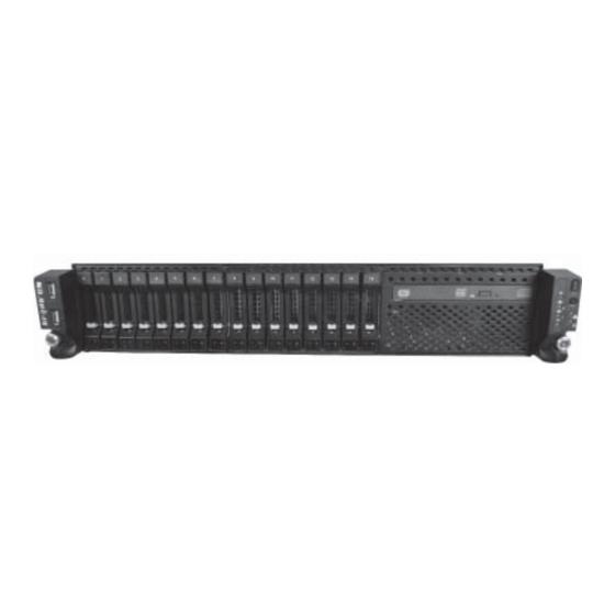
Chapter Two Product Introduction Chapter Two Product Introduction 2.2 Front Panel View 2.2 Front Panel View Note: The pictures are for reference only; please refer to your actual machines. 2.2.1 3.5 inches hard disk confi guration 2.2.1 3.5 inches hard disk confi guration Front panel view Number Name... - Page 15 Chapter Two Product Introduction Chapter Two Product Introduction Hard disk working The light is always green when hard disk is reading and status indicator light writing. Indicator light on The light is always red when hard disk fails. the hard The light is always blue when hard disk is being Hard disk failure disk...
- Page 16 Chapter Two Product Introduction Chapter Two Product Introduction ● Front-control Panel View Front panel schematic diagram Number Name Specifi cation Power button Server on/off button. ID light button To turn on ID light. It is always green when server operates. Power indicator light It is off when server closes.
-
Page 17: Back Panel View
Chapter Two Product Introduction Chapter Two Product Introduction ● Hard Disk Bracket Indicator Light Name Function and specifi cation Hard disk working status The light is always green when hard disk is reading and indicator light writing. The light is always red in case of hard disk failure. Hard disk failure alarm The light is always blue when hard disk is being located. -
Page 18: Chapter Three System Setup Chapter Three System Setup
Chapter Three System Setup Chapter Three System Setup In this chapter, the wire jumper of motherboard and BIOS function setup of this server are introduced. Only operator or manager with qualifi cation of system mainte- nance can implement these operations described in this part. 3.1 Main board BIOS setup 3.1 Main board BIOS setup BIOS is a basic input and output system. - Page 19 Chapter Three System Setup Chapter Three System Setup Menu name Menu function Confi guring the basic system setup, like the system time and date, Main and displaying the information of the system, such as BIOS, CPU and memory. Advanced Confi guring advanced characteristics in the chipset. PCIPnP Confi...
- Page 20 Chapter Three System Setup Chapter Three System Setup I. Main menu I. Main menu The Main menu appears fi rst when entering the BIOS setup system. The BIOS version information, processor information and memory capacity can be examined here and the system date and time can be set. Arrow keys can be used to select options.
- Page 21 Chapter Three System Setup Chapter Three System Setup (Note: the item Channel Number in Set LAN Confi guration can only be manually set to channel 01 or channel 08. Default setting is channel 01; if you need to use the network card 1 as the management interface, you need to set it to channel 08.) ●...
- Page 22 Chapter Three System Setup Chapter Three System Setup If you haven’t set the super-user password, select this menu and press <Enter>, you can set super-user password. If you have already set the super-user password, select this menu and press <En- ter>...
-
Page 23: Motherboard Jumper Settings
Open the Case Upper Panel Open the Case Upper Panel If the operation hereafter is needed, please get the authorization of Inspur Group Co., Ltd. according to the methods as follows to open the case upper panel: 1. Power off the system (turn off the AC power), then loosen the screws fi xed on... - Page 24 Chapter Three System Setup Chapter Three System Setup the upper panel at the right and left sides of the case; 2. Loosen the two screws built on the rear point of the upper panel and remove the upper panel according to arrow in the picture below. Clearing CMOS Jumper Introduction Clearing CMOS Jumper Introduction CLR_CMOS Jumper Location View...
-
Page 25: Chapter Four Setup Of Sata Hostraid Chapter Four Setup Of Sata Hostraid
Chapter Four Setup of SATA HostRAID Chapter Four Setup of SATA HostRAID This chapter mainly introduces the confi guration of controller HostRAID of main- board Intel SATA and its application method. If the server you purchased does not use SATA HostRAID, you can not refer to this chapter. - Page 26 Chapter Three System Setup Chapter Three System Setup The executable menus of the confi guration interface of SATA HostRAID are the following fi ve: ● Create RAID Volume Create RAID Volume. ● Delete RAID Volume Delete the existing RAID Volume. ●...
- Page 27 Chapter Three System Setup Chapter Three System Setup RAID0: it allows two or more than two hard disks to form this RAID volume. RAID1: it allows two hard disks to form this RAID volume. Recovery: it allows two hard disks to form this RAID volume, and this function is Intel Rapid Recover Technology.
- Page 28 Chapter Three System Setup Chapter Three System Setup Warning: ALL DISKS DATA WILL BE DELETED. If it confi rms to delete RAID volume, please press <DEL> key, and the system will pop up again the warning: ‘ALL DATA IN THE VOLUME WILL BE LOST! Are you sure you want to delete ‘Volume*’? (Y/N):’, and if yes, please enter ‘Y’, if not, please enter ‘N’.
-
Page 29: Chapter Five Operating System Installation Chapter Five Operating System Installation
During manual setup of the operating system, some operating system may need the fl oppy drive or Inspur drive U disk to load the driver of hard disk controller. Refer to the readme.pdf fi le under the root directory in Inspur system driver CD for the mak- ing method of the driver fl... -
Page 30: Application Instructions For Inspur Drive U Disk
U disk to load the drive of hard disk controller (at present, the operating systems that use Inspur drive U disk to load support of the hard disk controller are Windows XP and above versions, Red Hat Linux 4.5 and above versions, Suse Linux 9.0 SP2 and above versions systems). - Page 31 Windows system shall be identifi ed to be A:,and only by this can the normal fabrication of subsequent driver be guaranteed. 2. Put the driver CD (Inspur system driver CD and RAID card driver CD) into the CD driver, and the driver making software will operate automatically. If the system forbids the automatic operation of CD, please enter CD contents and operate documents of dolphin.bat (Inspur system driver CD) in CD or setup.exe (RAID car driver CD) in...
- Page 32 Chapter Five Installation of the Operating system Chapter Five Installation of the Operating system Input the navigation code in the text box (the navigation code is shown in CD box), click [OK] button, it can log in the main interface of driver making software. Click [Cancel] button and exit the logging.
- Page 33 The system will display a warning as shown in the following picture. Please confi rm that Inspur driving U disk is well connected, and format the fl oppy A: of Inspur driving U disk, and then click [OK] to start the driver making.
-
Page 34: Manually Install Windows Server 2003 Enterprise Edition
Inspur driver U disk, entering the interface of disk partition, the Inspur driver U disk will occupy a disk characteristic. If the disk is not divided, U disk will occupy disk C: and if the disk has other partitions, U disk will occupy other disk characteristics (please distinguish according to the actual hard disk partition). - Page 35 5.2.2 Installation steps 5.2.2 Installation steps 1. Connect USB floppy or Inspur driving U disk to the USB interface of the server, power up to start the server, and put the installation CD of Windows Server 2003 into CD-ROM and select to boot from CD.
- Page 36 Chapter Five Installation of the Operating system Chapter Five Installation of the Operating system You can select the items based on the actual situation, select the unallocated space here and then press <C> key. 7. Program installation prompts: ⊙ To create a new partition, enter its size below and press ENTER. ⊙...
- Page 37 Chapter Five Installation of the Operating system Chapter Five Installation of the Operating system next step. 12. The system displays Regional and Language Options: It is suggested to use the default setting, and here click <Next> to continue the installation. 13.
- Page 38 CD for operating system of integrated SP2 patch. 22. Install Chipset patch (1) Insert the Inspur system driver CD into CD-ROM, input the navigation code on the driver CD set in the navigation code verifying interface popped up after the running of CD, click <OK>...
- Page 39 (5) The window ‘Hardware Update Wizard’ will be shown, select ‘Install from a list or specifi c location (Advanced)’, and click to continue. (6) Insert Inspur system driver CD into the CD-ROM, select ‘Search for the best driver in these locations’, then select ‘Include this location in the search’, and then select the path of the driver in the CD: \driver\video\nf5280m2\win03_32, and click <OK>.
-
Page 40: Manually Install Windows Server 2008 Enterprise Edition
● Installation CD (DVD, support the version of 32bit or EMT64 bit) of Windows Server 2008 Enterprise Edition. ● Inspur system driver CD. ● Please select the corresponding driver to the fabricated or installed version of ● Please select the corresponding driver to the fabricated or installed version of system according to the operating system version selected to install. - Page 41 14. Install Chipset patch (1) Insert Inspur system driver CD into CD-ROM, click the blue dolphin icon under the installation or operation procedure item in the automatically playing interface popped out after the disk’s running, and input the navigation code on the driver CD...
- Page 42 CD and restart the system. 15.Install Network card driver (1) Insert Inspur system driver CD into CD-ROM, click the blue dolphin icon under the installation or operation procedure item in the automatically playing interface popped out after the disk’s running, and input the navigation code on the driver CD case in the navigation code verifi...
-
Page 43: Manually Install Red Hat Enterprise Linux 5.2
5.4.1 Preparation prior to the installation ● Installation CD for Red Hat Enterprise Linux 5.2 (five pieces of CD or one piece of DVD). ● Inspur system driver CD. 5.4.2 Installation steps 5.4.2 Installation steps 1. Power up and start the system, put the installation disk into the driver (here take using DVD installation disk as example), and select to boot from the CD. - Page 44 Chapter Five Installation of the Operating system Chapter Five Installation of the Operating system installation. 4. The installation program goes to ‘Red Hat Enterprise Linux 5’ interface, click <Next> to continue the installation. 5. Select to install language version of the operating system, here we select ‘English (English)’...
- Page 45 Chapter Five Installation of the Operating system Chapter Five Installation of the Operating system 11. The installation program enters into time zone interface, select ‘Asia/ shanghai’(or your current time zone) and click <Next> to continue the installation. 12. The installation program enters into Root Password setting interface, set at least six fi...
- Page 46 27. Log into system. 5.4.3 Install network card driver 5.4.3 Install network card driver 1. Insert Inspur system driver CD into CD-ROM, click Applications and the Terminal menu in Accessories, and input the following in the windows: #mount /dev/cdrom /mnt <Enter>...
-
Page 47: Chapter Six Common Problems And Trouble-Shooting Chapter Six Common Problems And Trouble-Shooting
Chapter Six Common Problems and Trouble-shooting Chapter Six Common Problems and Trouble-shooting This chapter focuses on the common problems and Trouble-shooting of the server. If you are not sure with the cause of a failure and its removal method, please contact our customer service center for solution. - Page 48 5. Find another monitor for test if possible. 6. If the machine is installed with components other than Inspur ones. Please remove them fi rst.
- Page 49 4. It is suggested that you use the keyboard and mouse tested for compatibility by 4. It is suggested that you use the keyboard and mouse tested for compatibility by Inspur group or replace with other keyboard and mouse for testing. Inspur group or replace with other keyboard and mouse for testing.
-
Page 50: Ruijie Server Kit And Other Machine-Attached Software Problem
3. After having collected the basic information, please feedback the detailed alarm information to Inspur technical support personnel in a timely manner. We will make further analysis and judgment and help you solve the problem as soon as possible. -
Page 51: Additional Notes
6.3.4 Losing the machine-attached Ruijie server suite and System Driver program CD 6.3.4 Losing the machine-attached Ruijie server suite and System Driver program CD Please visit the Inspur’s official website and download the correct version corresponding with your machine model. -
Page 52: Technical Support Information
6.5 Technical support information 6.5 Technical support information If you have any doubt or unsolved problems in using Inspur server, please take the following measures: 1. If you have doubt in product configuration and specification details, please contact your supplier. -
Page 53: Chapter Seven Instructions Of Baseboard Management Controller Chapter Seven Instructions Of Baseboard Management Controller
Chapter Seven Instructions of Chapter Seven Instructions of baseboard management controller baseboard management controller According to different confi guration of purchased products, the chip of baseboard BMC will be different, the following will describe the application of baseboard management controller function. 7.1 Management Chip BMC IP 7.1 Management Chip BMC IP Onboard BMC IP can be checked and set in the menu of ‘Advanced’... -
Page 54: Function Menu Introduction
Chapter Seven Instructions of baseboard management controller Chapter Seven Instructions of baseboard management controller Please input default Username and Password: Please input default Username and Password: Username: root Username: root Password: superuser Password: superuser Notice: default Username and Password can conduct all module configurations and setting of permission. - Page 55 Chapter Seven Instructions of baseboard management controller Chapter Seven Instructions of baseboard management controller (1) Alerts: Add, edit or remove alert destinations. (2) Mouse mode: Change mouse mode. Set Mode to Absolute: the absolute mode mouse can switch freely between remote picture and local picture.
- Page 56 Chapter Seven Instructions of baseboard management controller Chapter Seven Instructions of baseboard management controller Redirection of operation remote control console can’t be included. Redirection of operation remote control console can’t be included. Console Redirection menu : redirect to console. After choosing this menu ,the system will enter the interface as the following chart . Click <Java Console>...
- Page 57 Chapter Seven Instructions of baseboard management controller Chapter Seven Instructions of baseboard management controller Options Functions Start Redirection Start connecting redirection console. Stop Redirection Stop connecting redirection console. Restart Restart connecting redirection console. Full screen display of redirection Full Screen console.
- Page 58 Chapter Seven Instructions of baseboard management controller Chapter Seven Instructions of baseboard management controller C. Remote desktop: Mouse set C. Remote desktop: Mouse set Click ‘Mouse’, select ‘Sync Cursor’ in the drop-down list, client’s mouse switches to remote server, menu of local mouse and redirection mouse is synchronized. When remote server is in textual interface and the mouse is not easily to switch, please select shortcut key <Alt>+<M>...
- Page 59 Chapter Seven Instructions of baseboard management controller Chapter Seven Instructions of baseboard management controller If the optical disk in the synchronous client-side CDROM is the activate disk or system subpanel, boost sequence should be set in the server BIOS. The installation model of ISO document is the same with that through CDROM installation, boost sequence should be selected in the server BIOS.
-
Page 60: Chapter Eight Server Installation Guide Chapter Eight Server Installation Guide
We recommend you to use the cabinet specially designed by Inspur for the server. If so, the internal of the cabinet should be already grounded. Please don’t change the ground joint in the cabinet unless it is of absolute necessity. -
Page 61: Components Needed By Server Installation
Chapter Eight Server Installation Guide Chapter Eight Server Installation Guide 8.2 Components needed by server installation 8.2 Components needed by server installation Accompanying guide rail suit of 2U server includes the following objects: 1. Guide rail 1 set (one for left and one for right rail) 2. -
Page 62: Install Guide Rail Into Cabinet
Chapter Eight Server Installation Guide Chapter Eight Server Installation Guide (picture 4). Picture 4 4. Make the smooth side of the inner rail confront the side of cabinet, get the holes on the inner rail and screws on cabinet corresponding with each other well, let the inner rail cling to the cabinet closely, then push the inner rail in the direction (rear of the machine) of red arrows shown in (picture 5), Clamp tightly the inner rail with double- screw bolts. - Page 63 Chapter Eight Server Installation Guide Chapter Eight Server Installation Guide Picture 6 2. Find out the screw accompanied with guide rail (picture 7); fi x well the second hole (picture 6) on the front and back frame corresponding to angle rail. Picture 7 3.
-
Page 64: Install The Server To Cabinet
Chapter Eight Server Installation Guide Chapter Eight Server Installation Guide 8.5 Install the server to cabinet 8.5 Install the server to cabinet 1. Raise the server and carry it close to the cabinet, and align the back of the server with the front of the cabinet. 2.
Need help?
Do you have a question about the Yingxin NF5280M2 and is the answer not in the manual?
Questions and answers