Table of Contents
Advertisement
Quick Links
Advertisement
Table of Contents

Related Manuals for Agilent Technologies 5975T LTM GC


Summary of Contents for Agilent Technologies 5975T LTM GC
- Page 1 Agilent 5975T LTM GC/MSD Operation Manual Agilent Technologies...
- Page 2 Do not proceed beyond a WARNING notice until the indicated conditions are fully understood and met. 5975T LTM GC/MSD Operation Manual...
- Page 3 About This Manual This manual contains information for operating the Agilent 5975T LTM GC/MSD system. “Introduction” Chapter 1 describes general information about the 5975T LTM GC/MSD, including a hardware description, general safety warnings, and hydrogen safety information. “Installing LTM Columns”...
- Page 4 Agilent gas chromatographs, mass selective detectors, and GC samplers. Included are localized versions of the information you need most, such as: 5975T LTM GC/MSD Operation Manual...
- Page 5 Agilent also provides customized information for the products you own through a customer portal. This web service provides many customizable services as well as information related directly to your Agilent products and orders. Log onto the portal at http://www.agilent.com/chem. 5975T LTM GC/MSD Operation Manual...
- Page 6 5975T LTM GC/MSD Operation Manual...
-
Page 7: Table Of Contents
Contents Introduction Abbreviations Used The GC/MSD GC/MSD Hardware Description Important Safety Warnings Hydrogen Safety Safety and Regulatory Certifications Cleaning/Recycling the Product Liquid Spillage Moving or Storing the GC/MSD Installing LTM Columns Overview Columns To Install an Inlet Guard Column in the Split/Splitless Inlet To Install an MSD Guard Column in the GC/MSD Interface To Install the LTM Module Assembly in the Instrument To Remove the LTM Module Assembly from the Instrument... - Page 8 To Measure Column Flow Linear Velocity To Confirm Column Flow To Tune the MSD To Verify System Performance High-Mass Testing (5975T LTM GC/MSDs) To Open the LTM/Guard Column Enclosure Door To Open the LCP/Analyzer Window To Remove the Analyzer Top Cover...
- Page 9 To Pump Down the MSD To Move or Store the Instrument General Maintenance Before Starting Maintaining the Vacuum System Maintaining the Analyzer Maintenance Methods To Change the Septum on the Split/Splitless Inlet To Change the Liner and O-Ring on the Split/Splitless Inlet To Bakeout the Column Flow Path To Bakeout Contaminants from the Split/Splitless Inlet To Remove the EI ion source...
- Page 10 5975T LTM-GC/MSD Operation Manual...
- Page 11 Hydrogen Safety Safety and Regulatory Certifications Cleaning/Recycling the Product Liquid Spillage Moving or Storing the GC/MSD This chapter provides an overview of the instrument hardware, hydrogen safety and other general safety precautions for the Agilent Technologies 5975T LTM GC/MSD. Agilent Technologies...
-
Page 12: Introduction
High-energy dynode (refers to detector and its power supply) Inside diameter Local Area Network Local control panel Low thermal mass Mass to charge ratio Mass Selective Detector Octafluoronaphthalene (calibrant) PFHT 2,4,6-tris(perfluoroheptyl)-1,3,5-triazine (calibrant) PFTBA Perfluorotributylamine (calibrant) 5975T LTM GC/MSD Operation Manual... - Page 13 Introduction Table 1 Abbreviations (continued) Abbreviation Definition Quad Quadrupole mass filter Radio frequency RFPA Radio frequency power amplifier Torr Unit of pressure, 1 mm Hg Turbo Turbomolecular (pump) 5975T LTM GC/MSD Operation Manual...
-
Page 14: The Gc/Msd
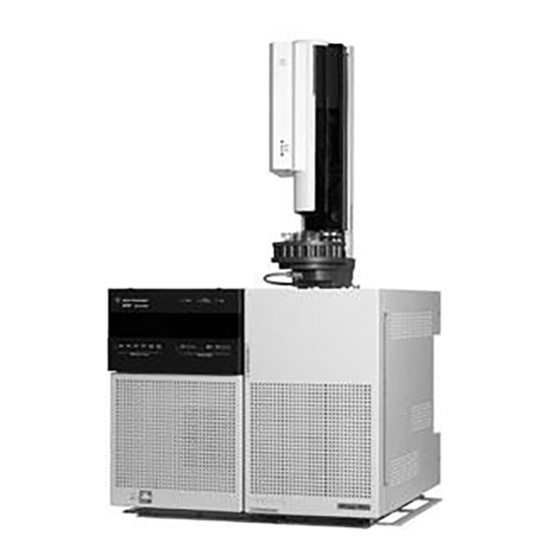
• ChemStation control for operating the GC/MSD Physical description The 5975T LTM GC/MSD is a rectangular box, approximately 41 cm high, 60 cm wide, and 54 cm deep. The weight is 46.5 kg for the mainframe. The attached foreline (roughing) pump weighs an additional 15 kg (standard pump) for wet, and 4.5 kg for dry. - Page 15 Introduction Table 2 5975T LTM GC/MSD models and features Feature High vacuum pump Standard turbo Optimal He column flow mL/min Maximum recommended column gas flow mL/min Maximum gas flow, mL/min Expect degradation of spectral performance and sensitivity. 5975T LTM GC/MSD Operation Manual...
-
Page 16: Gc/Msd Hardware Description
Introduction GC/MSD Hardware Description Figure 1 is an overview of a 5975T LTM GC/MSD system. Local control panel Door Door Power switch Figure 1 5975T LTM GC/MSD system 5975T LTM GC/MSD Operation Manual... - Page 17 Introduction ALS parking post Figure 2 Top View of 5975T with ALS parking post 5975T LTM GC/MSD Operation Manual...
-
Page 18: Important Safety Warnings
Do not touch any of the boards unless it is absolutely necessary. If you must handle them, wear a grounded wrist strap and take other antistatic precautions. Wear a grounded wrist strap any time you must remove the MSD right side cover. 5975T LTM GC/MSD Operation Manual... - Page 19 Combustible materials (or flammable/non-flammable wicking material) placed WA R N I N G under, over, or around the foreline (roughing) pump constitutes a fire hazard. Keep the pan clean, but do not leave absorbent material such as paper towels in it. 5975T LTM GC/MSD Operation Manual...
-
Page 20: Hydrogen Safety
• Hydrogen has a very low ignition energy. • Hydrogen that is allowed to expand rapidly from high pressure can self-ignite. • Hydrogen burns with a nonluminous flame which can be invisible under bright light. 5975T LTM GC/MSD Operation Manual... - Page 21 As a result, hydrogen may slowly accumulate in the mass spectrometer. However, in an external power failure, the EPC will be turned off and the flow of gas stopped. 5975T LTM GC/MSD Operation Manual...
- Page 22 Do not overtighten the thumbscrew; it can cause air leaks. Failure to secure your MSD as described above greatly increases the chance of WA R N I N G personal injury in the event of an explosion. 5975T LTM GC/MSD Operation Manual...
- Page 23 Environmental Health and Safety (EHS) requirements. Always check for leaks after changing a tank or servicing the gas lines. Always make sure the vent line is vented into a fume hood. 5975T LTM GC/MSD Operation Manual...
-
Page 24: Safety And Regulatory Certifications
• AUS/NZ This ISM device complies with Canadian ICES-001. Cet appareil ISM est conforme a la norme NMB—001 du Canada. The 5975T LTM GC/MSD is designed and manufactured under a quality system registered to ISO 9001. Information The Agilent Technologies 5975T LTM GC/MSD meets the following IEC (International Electro-technical Commission) classifications: Equipment Class I, Laboratory Equipment, Installation Category II, Pollution Degree 2. - Page 25 Failure to comply with these precautions violates safety standards of design and the intended use of the instrument. Agilent Technologies assumes no liability for the customer’s failure to comply with these requirements.
- Page 26 4 Make sure that all peripheral devices are also certified. 5 Make sure that appropriate cables are used to connect the device to peripheral equipment. 6 Consult your equipment dealer, Agilent Technologies, or an experienced technician for assistance. 7 Changes or modifications not expressly approved by Agilent Technologies could void the user’s authority to operate the equipment.
-
Page 27: Cleaning/Recycling The Product
The GC/MSD should not be left vented to atmosphere for long periods. Consult the Hardware Installation Manual for Field Transportable Units for information on how to secure, pack, transport and routinely set up the unit. 5975T LTM GC/MSD Operation Manual... - Page 28 Introduction 5975T LTM GC/MSD Operation Manual...
- Page 29 Agilent 5975T LTM GC/MSD Operation Manual Installing LTM Columns Overview Columns To Install an Inlet Guard Column in the Split/Splitless Inlet To Install an MSD Guard Column in the GC/MSD Interface To Install the LTM Module Assembly in the Instrument...
-
Page 30: Installing Ltm Columns
Installing LTM Columns Overview The LTM section of the 5975T LTM GC/MSD consists of a heated LTM column module and two guard columns that connect the LTM to the split/splitless inlet and MSD transfer line. These guard columns help limit contamination in the LTM, and the MSD. -
Page 31: Columns
A small portion of the capillary column stationary phase is often carried away by the carrier gas. This is called column bleed. Column bleed deposits traces of the stationary phase in the MSD ion source. This decreases MSD sensitivity and makes cleaning the ion source necessary. 5975T LTM GC/MSD Operation Manual... - Page 32 Tips and hints • The column installation procedures for the 5975T LTM GC/MSDs is different from that for previous MSDs. Using the procedure from another instrument may not work and may damage the column or the MSD.
-
Page 33: To Install An Inlet Guard Column In The Split/Splitless Inlet
Be careful! The guard column heated enclosure or internal accessories may be hot WA R N I N G enough to cause burns. If either is hot, wear heat-resistant gloves to protect your hands or allow the parts to cool before beginning the work. 5975T LTM GC/MSD Operation Manual... - Page 34 Ferrule, taper up Inlet column nut Septum Figure 4 Preparing a capillary column for installation 3 Use the sharp edge of the column cutter to score the column 2 cm from the end. See Figure 5975T LTM GC/MSD Operation Manual...
- Page 35 5 Inspect the end for jagged edges or burrs. If the break is not clean and even, repeat steps and 4. 6 Wipe the outside of the free end of the column with a lint-free cloth moistened with methanol. 5975T LTM GC/MSD Operation Manual...
- Page 36 11 Carefully wind the guard column clockwise around the three column brackets. See Figure 12 Check the Guard Column Enclosure to be sure that the column does not touch the heated walls. 5975T LTM GC/MSD Operation Manual...
- Page 37 Installing LTM Columns Inlet guard column Column brackets Figure 7 Column brackets 5975T LTM GC/MSD Operation Manual...
-
Page 38: To Install An Msd Guard Column In The Gc/Msd Interface
• Safety glasses • Wrench, open-end, 1/4-inch and 5/16-inch (8710-0510) Note that the column installation procedure for the 5975T LTM GC/MSDs is different C A U T I O N from that for most previous MSDs. Using the procedure from another instrument may result in poor sensitivity and possible damage to the MSD. - Page 39 GC/MSD interface. 3 Slide an interface nut and conditioned ferrule onto the free end of the guard column. The tapered end of the ferrule must point towards the nut. 5975T LTM GC/MSD Operation Manual...
- Page 40 Use the flashlight and hand lens if necessary to see the end of the column inside the analyzer chamber. Do not use your finger to feel for the column end. 8 Hand-tighten the nut. Make sure the position of the column does not change as you tighten the nut. 5975T LTM GC/MSD Operation Manual...
- Page 41 9 Tighten the nut 1/4 to 1/2 turn. Check the tightness after one or two heat cycles. 10 Carefully wind the guard column clockwise around the three column brackets. See Figure 11 Check the Guard Column Enclosure to be sure that the column does not touch the enclosure walls. 5975T LTM GC/MSD Operation Manual...
-
Page 42: To Install The Ltm Module Assembly In The Instrument
See Figure 3 Push the cable bundle into the bushing at the top of the slot to anchor the bundle. See Figure 5975T LTM GC/MSD Operation Manual... - Page 43 Installing LTM Columns Cable bundle holder Rectangular slot LTM module Figure 9 Cable Routing 5975T LTM GC/MSD Operation Manual...
- Page 44 When removing the transfer line connectors from the board, remove them by gripping the connector and not by pulling on the cable because there are several fine wires in the connector. See Figure 5975T LTM GC/MSD Operation Manual...
- Page 45 9 Connect the fan cable to the bottom connector. When securing the module do not over tighten! C A U T I O N LTM module 4 Captive screws Cables Fan cable Fan plate Figure 11 LTM module installed on the 5975T 5975T LTM GC/MSD Operation Manual...
- Page 46 “To Install an Inlet Guard Column in the Split/Splitless Inlet” on page 33, “To Install an MSD Guard Column in the GC/MSD Interface” on page 38, and “To Attach the Guard Columns to the LTM CFT Unions” page 52. 5975T LTM GC/MSD Operation Manual...
-
Page 47: To Remove The Ltm Module Assembly From The Instrument
If either is hot, wear heat-resistant gloves to protect your hands or allow the parts to cool before beginning the work. 3 Open the LTM door on the right side of the GC/MSD. 5975T LTM GC/MSD Operation Manual... - Page 48 Disconnect the power cord to the instrument from the building power supply. Never WA R N I N G power the instrument when changing the column module. Dangerous voltages exist inside the instrument when connected to the building power supply. 5975T LTM GC/MSD Operation Manual...
- Page 49 8 Remove the LTM column module by pulling it toward you out of the instrument. 9 Place the LTM column module on the bench space in the front of the instrument while you disconnect the cables. See Figure 5975T LTM GC/MSD Operation Manual...
- Page 50 Installing LTM Columns Cable bundle holder Rectangular slot LTM module Figure 13 Disconnecting the cables 5975T LTM GC/MSD Operation Manual...
- Page 51 13 Slide the bushing securing the cable bundle out of the attachment point on the frame to finish removing the column module assembly. See Figure 14 Cap the column ends and place the column module assembly in its storage container. 5975T LTM GC/MSD Operation Manual...
-
Page 52: To Attach The Guard Columns To The Ltm Cft Unions
Wear clean, lint-free gloves to prevent contamination of the parts. C A U T I O N 2 Pass the column end through the internal nut and SilTite ferrule leaving approximately 1 cm of fused silica column protruding beyond the ferrule. 5975T LTM GC/MSD Operation Manual... - Page 53 When the ferrule starts to grip, tighten one of the nuts an additional 45 to 60 degrees (one flat). 4 Remove the swaging nut or swaging tool. 5975T LTM GC/MSD Operation Manual...
- Page 54 8 If needed, install the free end of the guard column into the inlet or GC/MSD transfer line. See “To Install an Inlet Guard Column in the Split/Splitless Inlet” on page 33 or “To Install an MSD Guard Column in the GC/MSD Interface” on page 38. 5975T LTM GC/MSD Operation Manual...
- Page 55 Installing LTM Columns CFT Unions LTM bracket Figure 15 Guard columns attached 5975T LTM GC/MSD Operation Manual...
-
Page 56: To Condition The Ltm Column Module
C A U T I O N Procedure 1 If necessary, remove the existing LTM column module assembly. See “To Remove the LTM Module Assembly from the Instrument” on page 47. This leaves the instrument in a powered off state. 5975T LTM GC/MSD Operation Manual... - Page 57 14 Once the LTM column temperature exceeds 80 °C, inject 5 µL methanol into the inlet. Repeat two more times at 5-minute intervals. This helps remove any contamination from the column before it is installed into the GC/MSD interface. 5975T LTM GC/MSD Operation Manual...
- Page 58 LTM column temperature to a low standby temperature. See also For more information about installing a capillary column, refer to the application note Optimizing Splitless Injections on Your GC for High Performance MS Analysis, publication number 5988-9944EN. 5975T LTM GC/MSD Operation Manual...
-
Page 59: Operating In Electron Impact (Ei) Mode
To Measure Column Flow Linear Velocity To Confirm Column Flow To Tune the MSD To Verify System Performance High-Mass Testing (5975T LTM GC/MSDs) To Open the LTM/Guard Column Enclosure Door To Open the LCP/Analyzer Window To Remove the Analyzer Top Cover... - Page 60 The software and firmware are revised periodically. If the steps in these procedures do C A U T I O N not match your MSD ChemStation software, refer to the manuals and online help supplied with the software for more information. 5975T LTM GC/MSD Operation Manual...
-
Page 61: Operating The Gc/Msd From The Data System
Menu mode allows you to query various aspects of the GC/MSD and to initiate some actions like running a method or sequence or preparing to vent the system. To access a particular menu option: Press [Menu] until the desired menu appears. 5975T LTM GC/MSD Operation Manual... - Page 62 After you make your selection, or if you cycle through all available menus, the display automatically returns to Status mode. Pressing [Menu], then [No/Cancel], will always display the Status mode. Pressing [No/Cancel] twice will always return to the Status mode. 5975T LTM GC/MSD Operation Manual...
-
Page 63: Lcp Status Messages
The MSD’s firmware is being initialized. The following messages alternately appear on the LCP if the MSD does NOT complete its bootup sequence properly: Server not Found Check LAN Connection Seeking Server Bootp Query xxx 5975T LTM GC/MSD Operation Manual... - Page 64 The following messages are displayed on the LCP display during startup: • Loading OS • Loading MSD Firmware Continue to press the sideplate of the MSD until the MSD Ready message appears. This helps the instrument to pump down more quickly. 5975T LTM GC/MSD Operation Manual...
-
Page 65: Lcp Menus
Local = not connected to GC/MSD ChemStation online session Name of Instrument Displays the name of the instrument if connected to GC/MSD ChemStation online session. The name of the instrument is the name assigned by the GC/MSD ChemStation Configuration dialogue. 5975T LTM GC/MSD Operation Manual... - Page 66 Ping gateway Checks communication with the gateway. Ping ChemStation Checks communication with the GC/MSD ChemStation. Ping GC Checks communication with the GC. MS Controller MAC Displays the MAC address of the SmartCard in the MSD. 5975T LTM GC/MSD Operation Manual...
- Page 67 Displays the status of the GC inlet heater (Ready/Not Ready) GC-MSD Interface Displays the status of the GC-MSD interface temperature. GC Conn. Zone Heater Displays the status of the guard column enclosure heater. GC Column Heater Displays the status of the LTM heater. 5975T LTM GC/MSD Operation Manual...
- Page 68 Displays the subnet mask for the GC. Reboot LTM GC Now? Allows you to reboot the LTM GC. GC MAC Address Displays the MAC address for the GC. GC ChemStation IP Displays the IP address for the GC ChemStation. 5975T LTM GC/MSD Operation Manual...
-
Page 69: The Gc/Msd Interface
“To Install an MSD Guard Column in the GC/MSD Interface” The GC/MSD interface operates at high temperatures. If you touch it when it is hot, WA R N I N G it will burn you. 5975T LTM GC/MSD Operation Manual... - Page 70 Operating in Electron Impact (EI) Mode Heater sleeve Insulation Column Ionization chamber Guard column Analyzer enclosure chamber Heater/Sensor assembly Column end protrudes 1 to 2 mm into the ionization chamber. Figure 16 The GC/MSD interface 5975T LTM GC/MSD Operation Manual...
-
Page 71: Before You Turn On The Gc/Msd
WA R N I N G MSD has been pumped down. If the vacuum pumps are off, hydrogen will accumulate in the instrument and an explosion may occur. Read “Hydrogen Safety” before operating the instrument with hydrogen carrier gas. 5975T LTM GC/MSD Operation Manual... - Page 72 Read “Hydrogen Safety” before operating the MSD with hydrogen carrier gas. Pump down for 25 minutes before you turn on the vacuum gauge. 5975T LTM GC/MSD Operation Manual...
-
Page 73: Pumping Down
Carrier gas flow is controlled by head pressure in the GC inlet. For a given head pressure, column flow will decrease as the LTM column temperature increases. With electronic pneumatic control (EPC) and the column mode set to Constant Flow, the same column flow is maintained regardless of temperature. 5975T LTM GC/MSD Operation Manual... - Page 74 The MSD can be used to measure actual column flow. You inject a small amount of air or other unretained chemical and time how long it takes to reach the MSD. With this time measurement, you can calculate the column flow. See page 5975T LTM GC/MSD Operation Manual...
-
Page 75: Venting The Msd
Do not vent while the turbo pump is still spinning at more than 50%. Do not exceed the maximum recommended total gas flow. See Table 2, “5975T LTM GC/MSD models and features,” on page 15. 5975T LTM GC/MSD Operation Manual... -
Page 76: To View Msd Analyzer Temperature And Vacuum Status
1 In Instrument Control view, select Edit Tune Parameters from the Instrument menu (Figure 17). Figure 17 Tune parameters 2 Select the tune file you plan to use with your method from the Load MS Tune File dialog box. 5975T LTM GC/MSD Operation Manual... - Page 77 The MSD heaters turn on at the end of the pumpdown cycle and turn off at the beginning of the vent cycle. The reported setpoints will not change during venting or pumpdown, even though both the MSD zones are turned off. 5975T LTM GC/MSD Operation Manual...
-
Page 78: To Set Monitors For Msd Temperature And Vacuum Status
8 Click and drag each monitor to the desired position. See Figure 18 for one way of arranging the monitors. Figure 18 Arranging monitors 9 To make the new settings part of the method, select Save from the Method menu. 5975T LTM GC/MSD Operation Manual... -
Page 79: To Set The Msd Analyzer Temperatures
Do not exceed 200 °C for the quadrupole or 350 °C for the source. WA R N I N G 4 To close the screen, click: 5975T LTM GC/MSD Operation Manual... - Page 80 5 When the Save MS Tune File dialog box appears, either click OK to save your changes to the same file or type a new file name and click OK. Table 14 Recommended temperature settings EI operation MS Source MS Quad 5975T LTM GC/MSD Operation Manual...
-
Page 81: To Set The Gc/Msd Interface Temperature From The Chemstation
2 Select Instrument>GC Edit Parameters. 3 Click the Aux icon to edit the interface temperature (Figure 20). Figure 20 Setting the interface temperature 4 Check the heater On and type the setpoint in the Value °C column. 5975T LTM GC/MSD Operation Manual... - Page 82 6 To make the new settings part of the method, select Save from the Method menu. Make sure that the carrier gas is turned on and the column has been purged of air C A U T I O N before heating the GC/MSD interface or the LTM column. 5975T LTM GC/MSD Operation Manual...
-
Page 83: To Monitor High Vacuum Pressure
The largest influence on operating pressure in EI mode is the carrier gas (column) flow. Table 15 lists typical pressures for various helium carrier gas flows. These pressures are approximate and will vary from instrument to instrument by as much as 30%. 5975T LTM GC/MSD Operation Manual... - Page 84 1.3E–05 1.83E–05 2.61E–05 3.11E–05 5.25E–05 8.01E–05 If the pressure is consistently higher than those listed, refer to the online help in the MSD ChemStation software for information on troubleshooting air leaks and other vacuum problems. 5975T LTM GC/MSD Operation Manual...
-
Page 85: To Configure The Ltm Column
5 Click the first column labeled “1” (tooltip = Add/Modify this column) to display the Edit Properties of Installed GC Column dialog. The previously selected column is specified in the Additional Information (Optional) area. 5975T LTM GC/MSD Operation Manual... - Page 86 11 From the Configuration screen, select the Modules tab to display the screen where the carried gas for the inlet is displayed. 12 For the Front Inlet, select the carrier gas used from the dropdown menu. 13 Click the OK button to save this configuration. 5975T LTM GC/MSD Operation Manual...
-
Page 87: To Measure Column Flow Linear Velocity
7 To calculate the volumetric flow rate. 0.785 D Volumetric flow rate (mL/min) = --------------------------- - where: D = Internal column diameter in millimeters L = Column length in meters t = Retention time in minutes 5975T LTM GC/MSD Operation Manual... -
Page 88: To Confirm Column Flow
Procedure 1 In the Instrument Control view, select Instrument>GC Edit Parameters. 2 Click the Columns icon (Figure 21 shows an example). 3 Select the appropriate column. Figure 21 Calculating column flow 5975T LTM GC/MSD Operation Manual... -
Page 89: To Tune The Msd
From this Tune menu, in addition to the tunes available from Instrument Control, you can select special autotunes for specific spectral results, such as DFTPP Tune or BFB Tune. See the manuals or online help provided with your MSD ChemStation software for additional information about tuning. 5975T LTM GC/MSD Operation Manual... -
Page 90: To Verify System Performance
4 Click OK to run the method. When the method is completed, an evaluation report will be printed. Verify that rms signal-to-noise ratio meets the published specification. Please see the Agilent Web site at www.agilent.com/chem for specifications. 5975T LTM GC/MSD Operation Manual... -
Page 91: High-Mass Testing (5975T Ltm Gc/Msds)
Operating in Electron Impact (EI) Mode High-Mass Testing (5975T LTM GC/MSDs) Setup conditions 1 Obtain a sample of PFHT (5188-5357). 2 Load tune file ATUNE.U then auto tune the MSD. 3 Resolve the PFHT.M method under x\5975\PFHT.M where x is instrument number being used. - Page 92 Operating in Electron Impact (EI) Mode Results Figure 22 PFHT high mass report 5975T LTM GC/MSD Operation Manual...
- Page 93 5 Load the PFHT.M and the saved tune file, then save the method. 6 Rerun test mixture (repeat high-mass checkout). If the correction is within 5 units, no further adjustments are required. 5975T LTM GC/MSD Operation Manual...
-
Page 94: To Open The Ltm/Guard Column Enclosure Door
To Open the LTM/Guard Column Enclosure Door Push on the latch under the bottom left corner of the door to the LTM/guard column enclosure and open the door. LCP/Analyzer window LTM door Door Latch Figure 23 Removing covers 5975T LTM GC/MSD Operation Manual... -
Page 95: To Open The Lcp/Analyzer Window
3 Slide the cover forward until it is free of the mainframe, and lift it off the instrument. Captive cover screw Latches Analyzer top cover Captive cover screw LCP/Analyzer window Figure 24 Removing analyzer top cover 5975T LTM GC/MSD Operation Manual... - Page 96 Operating in Electron Impact (EI) Mode Do not remove any other covers. Dangerous voltages are present under other covers. WA R N I N G 5975T LTM GC/MSD Operation Manual...
-
Page 97: To Vent The Msd
When the MSD is vented, do not put the ChemStation into Instrument Control view. WA R N I N G Doing so will turn on the interface heater. 5 Open the LCP window. See “To Open the LCP/Analyzer Window” page 95 5975T LTM GC/MSD Operation Manual... - Page 98 C A U T I O N chamber. When the MSD is vented, do not put the ChemStation into Instrument Control view. WA R N I N G Doing so will turn on the interface heater. 5975T LTM GC/MSD Operation Manual...
-
Page 99: To Open The Analyzer Chamber
In the next step, if you feel resistance, stop. Do not try to force the side plate open. C A U T I O N Verify that MSD is vented. Verify that both the front and rear side plate screws are completely loose. 5975T LTM GC/MSD Operation Manual... - Page 100 Do not touch any part until you are sure it is cool. Always wear clean gloves to prevent contamination when working in the analyzer C A U T I O N chamber. 5975T LTM GC/MSD Operation Manual...
- Page 101 Operating in Electron Impact (EI) Mode Thumbscrews Side plate CHAMBER CLOSED Detector Side plate Feedthrough board Ion source CHAMBER OPEN Analyzer Figure 26 The analyzer chamber 5975T LTM GC/MSD Operation Manual...
-
Page 102: To Close The Analyzer Chamber
Board, top right (ION FOC) Ion focus lens Blue (1) Board, top right (ENT LENS) Entrance lens Green beaded (2) Ion source heater Board, bottom left (HTR) White (2) Ion source sensor Board, bottom (RTD) 5975T LTM GC/MSD Operation Manual... - Page 103 White wires to filament 1 FILAMENT - 1 Red wire to repeller FILAMENT - 2 Black wires to filament 2 Ion source heater wires (green) Ion source sensor wires (white) SOURCE Figure 27 Feedthrough board wiring 5975T LTM GC/MSD Operation Manual...
- Page 104 Make sure the O-ring has a very light coat of Apiezon L high vacuum grease. If the O-ring is very dry, it may not seal well. If the O-ring looks shiny, it has too much grease on it. (Refer to the 5975T LTM GC/MSD Troubleshooting and Maintenance Manual for lubricating instructions.)
- Page 105 Do not overtighten the thumbscrew; it can cause air leaks or prevent successful C A U T I O N pumpdown. Do not use a screwdriver to tighten the thumbscrew. 8 Once the MSD has pumped down, replace the analyzer cover and close the LCP/Analyzer window. 5975T LTM GC/MSD Operation Manual...
-
Page 106: To Pump Down The Msd
The foreline pump will make a gurgling noise. This noise should stop within a minute. If the noise continues, there is a air leak in your system, large probably at the side plate seal, the interface column nut, or the vent valve. 6 Close the LCP/Analyzer window. 5975T LTM GC/MSD Operation Manual... - Page 107 9 After the message Okay to run appears, wait 2 hours for the MSD to reach thermal equilibrium. Data acquired before the MSD has reached thermal equilibrium may not be reproducible. 5975T LTM GC/MSD Operation Manual...
-
Page 108: To Move Or Store The Instrument
This procedure is for moving or storing the instrument around the same location. If the instrument needs to be shipped for use in a different location, please refer to the Agilent 5975T LTM GC/MSD Hardware Installation Manual for Field Transportable Units for the appropriate instructions. - Page 109 The GC/MSD must remain upright at all times. If you need to ship your GC/MSD to C A U T I O N another location, contact your Agilent Technologies service representative for advice about packing and shipping. 5975T LTM GC/MSD Operation Manual...
- Page 110 Operating in Electron Impact (EI) Mode 5975T LTM GC/MSD Operation Manual...
- Page 111 Agilent 5975T LTM GC/MSD Operation Manual General Maintenance Before Starting Maintaining the Vacuum System Maintaining the Analyzer Maintenance Methods To Change the Septum on the Split/Splitless Inlet To Change the Liner and O-Ring on the Split/Splitless Inlet To Bakeout the Column Flow Path...
-
Page 112: Before Starting
Lubricate sideplate or vent valve O-rings Tune the MSD Clean the ion source Check the calibration vial(s) Check the carrier gas trap(s) on the GC Trim or replace the guard columns Replace inlet septum, liner, and o-ring 5975T LTM GC/MSD Operation Manual... - Page 113 Perform no maintenance with the instrument turned on or plugged into its power WA R N I N G source unless you are instructed to by one of the procedures in this chapter. 5975T LTM GC/MSD Operation Manual...
- Page 114 The split vent outlet and purge vent outlet contain high concentrations of the chemicals you are analyzing along with the carrier gas. If you are processing hazardous chemicals, these outlets should be vented to a safe location outside the laboratory. 5975T LTM GC/MSD Operation Manual...
- Page 115 (quadrupole) contact wires which can carry ESD to sensitive components on the side board. ESD damage may not cause immediate failure but it will gradually degrade the performance and stability of your MSD. 5975T LTM GC/MSD Operation Manual...
- Page 116 Antistatic precautions are not 100% effective. Handle electronic circuit boards as little as possible and then only by the edges. Never touch components, exposed traces, or pins on connectors and cables. 5975T LTM GC/MSD Operation Manual...
-
Page 117: Maintaining The Vacuum System
Other procedures Tasks such as replacing a Micro-Ion vacuum gauge should be performed only when needed. See the Agilent 5975T LTM GC/MSD Troubleshooting and Maintenance Manual or the online help in the MSD ChemStation software for symptoms that indicate this type of maintenance is required. -
Page 118: Maintaining The Analyzer
None of the analyzer components require periodic maintenance. Some tasks, however, must be performed when GC/MSD behavior indicates they are necessary. The Agilent 5975T LTM GC/MSD Troubleshooting and Maintenance Manual provides information about symptoms that indicate the need for analyzer maintenance. The troubleshooting material in the online help in the ChemStation software provides more extensive information. - Page 119 Do not touch the HED ceramic insulator. More information is available If you need more information about the locations or functions of analyzer components, refer to the Agilent 5975T LTM GC/MSD Troubleshooting and Maintenance Manual. Many procedures in this manual are illustrated with video clips.
-
Page 120: Maintenance Methods
Be careful! The LTM column, guard column enclosure, GC/MSD transfer line, WA R N I N G analyzer and inlet may be hot enough to cause burns. If hot, wear heat-resistant gloves to protect your hands. 5975T LTM GC/MSD Operation Manual... -
Page 121: To Change The Septum On The Split/Splitless Inlet
2 Remove the septum retainer nut or Merlin cap. 3 Use tweezers to remove the septum or Merlin Microseal from the retainer nut. Do not gouge or scratch the interior of the septum head. 5975T LTM GC/MSD Operation Manual... - Page 122 5 Install the septum retainer nut or Merlin cap and finger-tighten. Tighten the septum retainer nut until the C-ring is about 1 mm above the nut. 1 mm 6 Restore the analytical method. 7 Reset the septum counter. 5975T LTM GC/MSD Operation Manual...
-
Page 123: To Change The Liner And O-Ring On The Split/Splitless Inlet
Direct inject —Headspace or purge and trap 1.5-mm id, 140 µL (18740-80200) • Direct column connect Single taper, splitless 4-mm id (G1544-80730) • Direct column connect Dual taper, splitless 4-mm id (G1544-80700) • Tweezers • Wrench, hex for changing septum • Wrench, capillary inlet (optional) 5975T LTM GC/MSD Operation Manual... - Page 124 2 Slide the locking tab forward (counterclockwise). Lift the septum assembly straight up and away from the inlet to avoid chipping or breaking the liner. 3 Loosen the O-ring from the sealing surface with tweezers. 5975T LTM GC/MSD Operation Manual...
- Page 125 4 Grasp the liner with tweezers and pull it out. 5 Inspect the surface of the gold seal for graphite or rubber septum contamination. If required, replace the gold seal. (See the Agilent 5975T LTM GC/MSD Troubleshooting and Maintenance Manual.) 5975T LTM GC/MSD Operation Manual...
- Page 126 General Maintenance Clean the inlet if there is visible or suspected contamination. (See the Agilent 5975T LTM GC/MSD Troubleshooting and Maintenance Manual.) Clean O-ring residue from sealing surface. Wear clean, lint-free gloves to prevent contamination of parts with dirt and skin oils.
- Page 127 9 Turn on the inlet. Allow the inlet and column to purge with carrier gas for 15 minutes before heating the inlet or the LTM column. 10 Restore the analytical method. 11 Reset the liner counter. 12 Check for leaks. 5975T LTM GC/MSD Operation Manual...
-
Page 128: To Bakeout The Column Flow Path
Wear clean, lint-free gloves to prevent contamination of the parts. C A U T I O N 2 Vent the instrument. See “Venting the MSD” on page 75. 5975T LTM GC/MSD Operation Manual... - Page 129 15 Once the LTM column temperature exceeds 80 °C, inject 5 µL methanol into the inlet. Repeat two more times at 5-minute intervals. This helps remove any contamination from the column before it is installed into the GC/MSD interface. 5975T LTM GC/MSD Operation Manual...
- Page 130 24 With a column flow of 30 cm/s, wait for 5 to 10 minutes before increasing the LTM column temperature to a low standby temperature. 25 Restore the analytical method. 5975T LTM GC/MSD Operation Manual...
-
Page 131: To Bakeout Contaminants From The Split/Splitless Inlet
7 Set the LTM column to 25 °C above the method final column temperature to bake contaminants from the column. Do not exceed the column manufacturer’s maximum temperature limit. 8 Hold these system temperatures and flows for 30 minutes. 9 Restore the analytical method. 5975T LTM GC/MSD Operation Manual... -
Page 132: To Remove The Ei Ion Source
(Figure 31 Table 18). Table 18 Ion source wires Wire color Connects to Number of leads Blue Entrance lens Orange Ion focus White Filament 1 (top filament) Repeller Black Filament 2 (bottom filament) 5975T LTM GC/MSD Operation Manual... - Page 133 5 Remove the thumbscrews that hold the ion source in place. 6 Pull the ion source out of the source radiator. The analyzer operates at high temperatures. Do not touch any part until you are sure WA R N I N G it is cool. 5975T LTM GC/MSD Operation Manual...
- Page 134 General Maintenance Source feedthrough board Ion source Thumbscrews Source heater and temperature sensor wires Source radiator Figure 31 Removing the ion source 5975T LTM GC/MSD Operation Manual...
-
Page 135: To Reinstall The Ei Ion Source
1 Slide the ion source into the source radiator (Figure 32). 2 Install and hand tighten the source thumbscrews. Do not overtighten the thumbscrews. 3 Connect the ion source wires as shown in “To Close the Analyzer Chamber” Close the analyzer chamber. 5975T LTM GC/MSD Operation Manual... - Page 136 General Maintenance 4 Pump down the MSD. See page 106. Ion source Thumbscrews Source radiator Figure 32 Installing the EI ion source 5975T LTM GC/MSD Operation Manual...
- Page 138 Agilent Technologies © Agilent Technologies, Inc. Printed in USA, December 2010...