Hughes HughesNet HN9000 Installation Manual
Hide thumbs
Also See for HughesNet HN9000:
- User manual (82 pages) ,
- Manual (10 pages) ,
- Replacement manual (2 pages)
Table of Contents
Advertisement
Quick Links
Advertisement
Table of Contents
Troubleshooting

Related Manuals for Hughes HughesNet HN9000


Summary of Contents for Hughes HughesNet HN9000
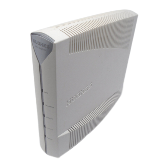
- Page 1 HN9000 Satellite Modem Installation Guide 1037576-0001 Revision A March 21, 2008...
- Page 2 Hughes Network Systems, LLC has made every effort to ensure the correctness and completeness of the material in this document. Hughes Network Systems, LLC shall not be liable for errors contained herein. The information in this document is subject to change without notice. Hughes Network Systems, LLC makes no warranty of any kind with regard to this material, including, but not limited to, the implied warranties of merchantability and fitness for a particular purpose.
-
Page 3: Table Of Contents
Contents Understanding safety messages..................xi Additional safety symbols........................xi Scope and audience......................xiii Part I: Satellite modem installation..............1 Chapter 1: Satellite modem overview...........3 Supported configurations......................4 Satellite modem specifications.....................5 Chapter 2: Preparing for installation............7 Installation summary........................8 Conducting a site survey......................9 Instructions for other terminal components..................9 Power supply information......................9 Primary tools and equipment needed for installation..............10 Additional equipment ........................11... - Page 4 Contents Chapter 5: Commissioning the satellite modem.........31 Prerequisites for commissioning....................32 Monitoring the commissioning process ..................32 Implementation of second IP address................34 Commissioning and installation reference information..........34 Commissioning activities and progress messages..........34 Registration error messages................36 Terminal Info parameters...................37 Troubleshooting installation problems..................39 Chapter 6: Activating the HughesNet service........41 Connecting the satellite modem to the customer’s computer.............42 The customer’s role –...
- Page 5 Contents System Information page......................66 State codes..........................67 Viewing the state codes list....................70 Connectivity Test page.......................71 Chapter 9: LEDs..................73 Front panel LEDs........................74 LAN port LEDs..........................75 Chapter 10: Troubleshooting..............77 Cannot Access the System Control Center.................78 Testing connectivity to the satellite....................78 Chapter 11: Advanced Pages..............81 Accessing the Advanced Pages....................82 Expanding and collapsing menus....................83 Opening the Installation sub-menu.....................84...
- Page 7 Table of Figures Figure 1: HN9000 satellite modem ..........................3 Figure 2: Single-host configuration..........................4 Figure 3: Multiple-host configuration in an Ethernet wired LAN...................4 Figure 4: Private network configuration..........................5 Figure 5: Satellite modem installation summary......................8 Figure 6: Power supply for the HN9000 satellite modem....................10 Figure 7: Internet Protocol Properties dialog.........................13 Figure 8: Settings for primary and alternate addresses on the laptop................15 Figure 9: HN9000 in vertical position..........................18...
- Page 8 Table of Figures Figure 42: Reception Information page..........................63 Figure 43: Transmission Information page........................64 Figure 44: Terminal Status page (top part)........................66 Figure 45: System Information page (top part)......................66 Figure 46: Examples of state codes..........................67 Figure 47: Terminal Connectivity Test page........................71 Figure 48: Front panel LEDs on the HN9000 modem....................74 Figure 49: LAN port LEDs............................75 Figure 50: Satellite loopback connectivity test......................78 Figure 51: Terminal Connectivity Test page........................79...
- Page 9 Table of Tables Table 1: Specifications for the HN9000 satellite modem....................5 Table 2: Related installation documents...........................9 Table 3: Power supply specifications for the HN9000 satellite modem................10 Table 4: Commissioning progress messages........................34 Table 5: Reasons for registration errors and corrective actions..................36 Table 6: Parameters in Terminal Info section (appears on two installation screens).............37 Table 7: Guidelines for installation troubleshooting......................39 Table 8: Button links on System Control Center screens....................59...
-
Page 11: Understanding Safety Messages
Understanding safety messages Three types of safety messages are defined according to the severity of the possible hazard each type of message addresses. This section explains the meaning of the safety alert symbol and specific words that are used in this Guide to bring your attention to safety information. -
Page 13: Scope And Audience
Scope and audience This Installation Guide explains how to install, commission, activate, and troubleshoot the Hughes HN9000 satellite modem. It also contains certain reference information concerning operation of the satellite modem. This Guide is written primarily for professional installers. It may also be useful for: •... -
Page 15: Part I: Satellite Modem Installation
Part Satellite modem installation Topics: Satellite modem overview Preparing for installation Installing the satellite modem Installing outdoor equipment and antenna pointing Commissioning the satellite modem Activating the HughesNet service Completing the installation... -
Page 17: Chapter 1: Satellite Modem Overview
Chapter Satellite modem overview Topics: The HN9000 satellite modem connects to the Internet or an intranet by satellite and provides Internet or intranet service to a single host, typically a computer, Supported configurations or to multiple hosts on a LAN. A host may be a computer using Windows or Satellite modem specifications other supported operating system. -
Page 18: Supported Configurations
(a computer), as shown in Figure 2: Single-host configuration on page 4. The Hughes Internet Gateway is a Hughes-operated satellite station that provides a connection between the Internet and the satellite. The gateway routes data to and from the Internet and to and from the satellite, which in turn beams a signal down to the satellite modem to provide Internet connectivity. -
Page 19: Satellite Modem Specifications
HN9000 Satellite Modem Installation Guide Chapter 1 1037576-0001 Rev. A based upon the network design for the customer private network. Typically this type of configuration is used only in enterprise (business) environments. Figure 4: Private network configuration Satellite modem specifications Table 1: Specifications for the HN9000 satellite modem Weight 1.6 lb (0.73 kg) -
Page 21: Chapter 2: Preparing For Installation
Chapter Preparing for installation Topics: This section describes preparations for installing the satellite modem and includes information you should know before you begin. Review this information before Installation summary you install the satellite modem, antenna assembly, antenna mount, or IFL cables. Conducting a site survey Refer also to Installation summary on page 8. -
Page 22: Installation Summary
Chapter 2 HN9000 Satellite Modem Installation Guide 1037576-0001 Rev. A Installation summary This Installation Guide covers installation of the satellite modem. It does not cover installation of the other satellite terminal components: the antenna and radio assembly, antenna mount, and IFL cables. However, to understand modem installation, you must understand the overall installation process, which includes installation of all of the satellite terminal components. -
Page 23: Conducting A Site Survey
HN9000 Satellite Modem Installation Guide Chapter 2 1037576-0001 Rev. A Complete the steps in the order shown in Figure 5: Satellite modem installation summary on page 8 unless you have a specific reason for doing them in a different order. In any case, make sure all steps are completed. Be aware that the satellite modem has to provide the azimuth, elevation, polarization, and tilt angle values before antenna pointing can be completed. -
Page 24: Primary Tools And Equipment Needed For Installation
Chapter 2 HN9000 Satellite Modem Installation Guide 1037576-0001 Rev. A Figure 6: Power supply for the HN9000 satellite modem Before proceeding, make sure you have the correct power supply. Check the part number on the power supply and refer to Table 3: Power supply specifications for the HN9000 satellite modem on page 10. •... -
Page 25: Additional Equipment
HN9000 Satellite Modem Installation Guide Chapter 2 1037576-0001 Rev. A • Ethernet cable. To install the satellite modem, antenna assembly, and IFL cables you also need the additional items listed below. • Antenna. • IFL cables, cable connectors, and ground blocks – You need enough cable to connect the satellite modem to the antenna (transmit cable and receive cable). -
Page 26: A Hub May Be Required
Requirements are listed by operating system. All requirements are minimum requirements except those identified as recommended. The satellite modem may work with a computer that does not meet these requirements, but Hughes supports only computers that meet these requirements. -
Page 27: Setting The Installer Laptop Ip Address
HN9000 Satellite Modem Installation Guide Chapter 2 1037576-0001 Rev. A Internet browser • Internet Explorer 6 or greater, Netscape Navigator, Mozilla Firefox, Safari (for Windows and Mac) • Browser settings: • HTTP 1.1 or greater enabled • Proxy settings disabled Setting the installer laptop IP address These instructions explain how to set a specific public IP address on the installer laptop computer. -
Page 28: Setting An Alternate Ip Address On The Installer Laptop
Chapter 2 HN9000 Satellite Modem Installation Guide 1037576-0001 Rev. A e) Click OK twice to close the Internet Protocol Properties dialog and the Network Connections dialog. The laptop computer IP address is now set up to communicate with the satellite modem. If the customer’s computer has a problem, you can use the installer laptop to connect to and check the satellite modem. -
Page 29: Figure 8: Settings For Primary And Alternate Addresses On The Laptop
HN9000 Satellite Modem Installation Guide Chapter 2 1037576-0001 Rev. A Figure 8: Settings for primary and alternate addresses on the laptop... -
Page 31: Chapter 3: Installing The Satellite Modem
Note: In some cases re-installation may correct a specific service problem. Re-installation should only be done by a qualified installer or service technician or someone under specific direction by Hughes Customer Care. The installation software is factory pre-installed in the satellite modem. If necessary, this software is automatically updated as part of the installation process. -
Page 32: Selecting The Modem Location
Chapter 3 HN9000 Satellite Modem Installation Guide 1037576-0001 Rev. A Selecting the modem location Select a location for the satellite modem that will accommodate all required cable connections, including the power source. Place the modem in the desired location. • Do not block any ventilation openings. -
Page 33: Connecting The Installer Laptop To The Modem
HN9000 Satellite Modem Installation Guide Chapter 3 1037576-0001 Rev. A The Power LED turns on, and various LEDs turn on and off as the modem performs a self-test and transitions to boot phase. (Indication that the self-test passed appears later as Self Test : Passed on the screen shown in Figure 20: Terminal Initialization Sequence complete on page 33.) Figure 10: Powering up the modem A suitable surge protector is recommended to protect the satellite modem from possible damage due to power surges. -
Page 34: Entering The Installation Parameters
Chapter 3 HN9000 Satellite Modem Installation Guide 1037576-0001 Rev. A Figure 11: Connecting the installer's laptop computer to the modem 2. Make sure the satellite modem is not connected to the customer’s computer. 3. If you are running firewall software on the laptop computer, disable it until you complete installation of the modem. The LAN LED on the front of the modem should now be on. -
Page 35: Figure 12: System Control Center Home Page
HN9000 Satellite Modem Installation Guide Chapter 3 1037576-0001 Rev. A Figure 12: System Control Center home page The System Status and System Info buttons are always visible near the top of the System Control Center screens. Three additional buttons are visible after the modem has been commissioned and is operational. 3. -
Page 36: Figure 14: Installation Screen
Chapter 3 HN9000 Satellite Modem Installation Guide 1037576-0001 Rev. A Figure 14: Installation screen Note: On some screens you may see the word terminal. This word refers to the satellite modem. 4. For each of the following parameters, select the value that is listed on the Installation Reference Sheet: •... -
Page 37: Figure 15: Example Of A Gps Receiver Display
You can type your own value in the space that reads, Enter Your Own Value—but do this only if you are specifically instructed to do so by Hughes Installer Support. Note: You can clear previously entered installation information by clicking Control in the screen’s left panel, and then clicking Clear Terminal Install. -
Page 38: Figure 16: Terminal Pointing Info Screen
Chapter 3 HN9000 Satellite Modem Installation Guide 1037576-0001 Rev. A Note: The state code, which appears below the latitude and longitude values, indicates the current operational state of the satellite modem. While you are entering installation parameters but before you click Submit Installation Parameters, the state code is 2 (which means waiting for installation parameters). - Page 39 HN9000 Satellite Modem Installation Guide Chapter 3 1037576-0001 Rev. A • ODU polarization setting (LHCP or RHCP) You will need the azimuth and elevation values to point the antenna. Note: When you install the antenna, be sure to set LHCP or RHCP as indicated on the Terminal Pointing Info screen (Setting for ODU Polarization).
-
Page 41: Chapter 4: Installing Outdoor Equipment And Antenna Pointing
Chapter Installing outdoor equipment and antenna pointing Topics: After you enter the installation parameters on the Installation screen and click Submit Installation Parameters, the satellite modem enters pointing mode. Installing the IFL cables This allows you to point the antenna. Pointing the antenna This section provides some general information about antenna installation and pointing, especially as these tasks relate to modem installation. -
Page 42: Installing The Ifl Cables
(See also Requirements for IFL cables, connectors, and ground blocks on page 11.) Routing and connecting the IFL cables To point the antenna, you must connect the modem to the antenna and install the DAPT (a Hughes tool that displays antenna pointing values.) 1. -
Page 43: Labeling The Ifl Cables
HN9000 Satellite Modem Installation Guide Chapter 4 1037576-0001 Rev. A Labeling the IFL cables Label the receive and transmit IFL cables at the outdoor point-of-entry and at the indoor location where the satellite modem is installed as follows: • Wrap a piece of red electrical tape around the receive cable, and mark SAT IN on the tape. •... -
Page 44: Pointing The Antenna
Chapter 4 HN9000 Satellite Modem Installation Guide 1037576-0001 Rev. A Pointing the antenna Make sure you have the DAPT and the correct squinter for the radio assembly to be installed. You will need these tools to point the antenna. 1. Go outside to the antenna location. 2. -
Page 45: Chapter 5: Commissioning The Satellite Modem
Chapter Commissioning the satellite modem Topics: During the commissioning phase of installation the satellite modem downloads software and completes other activities so it can become an operational element Prerequisites for commissioning of the network. When commissioning is completed, the modem is ready for Monitoring the commissioning service activation. -
Page 46: Prerequisites For Commissioning
Chapter 5 HN9000 Satellite Modem Installation Guide 1037576-0001 Rev. A Prerequisites for commissioning The following are pre-requisites for commissioning: • The satellite modem must be physically installed. • The antenna must be pointed, and the modem must have exited pointing mode. •... -
Page 47: Figure 20: Terminal Initialization Sequence Complete
HN9000 Satellite Modem Installation Guide Chapter 5 1037576-0001 Rev. A Note: Downloading the commissioning software, if required, takes approximately 5 minutes. Do not remove power during this download because you think it's taking too long. If you do, you will have to wait until the commissioning software is broadcast again from the NOCC plus the download time. -
Page 48: Implementation Of Second Ip Address
Chapter 5 HN9000 Satellite Modem Installation Guide 1037576-0001 Rev. A Successful commissioning ends with the modem rebooting into normal operational mode. For detailed information about the commissioning process, the Terminal Initialization Sequence screen, and possible error messages, see Commissioning and installation reference information on page 34. There is also a section on installation troubleshooting (Troubleshooting installation problems on page 39). - Page 49 HN9000 Satellite Modem Installation Guide Chapter 5 1037576-0001 Rev. A Commissioning Waiting for System Information Software Downloading beginning... Download Completed Please wait for next broadcast of Software in {number} mins... Satellite Uplink Signal Uplink signal acquisition failed (Ack attempt # {number})... Acquiring Signal Attempting Probing (attempt # {number}) ...
-
Page 50: Registration Error Messages
Chapter 5 HN9000 Satellite Modem Installation Guide 1037576-0001 Rev. A Registration error messages Modem registration refers to registration with the satellite network. Even after registration, the modem cannot connect to the Internet until it is activated. Reasons for possible registration error messages are listed in Table 5: Reasons for registration errors and corrective actions on page 36. -
Page 51: Terminal Info Parameters
HN9000 Satellite Modem Installation Guide Chapter 5 1037576-0001 Rev. A Error message Reason Corrective action antenna. If the problem is not corrected, repoint the antenna. Tx Air Interface Down Satellite transmit link is down. Verify the installation, for example, check cable connections and connectivity to the antenna. - Page 52 Chapter 5 HN9000 Satellite Modem Installation Guide 1037576-0001 Rev. A Parameter Possible values Comments SQF at azimuth 1 position 0 – 255 Receive signal strength with squinter in azimuth 1 position during antenna pointing. SQF at elevation 1 position 0 – 255 Receive signal strength with squinter in elevation 1 position during antenna pointing.
-
Page 53: Troubleshooting Installation Problems
HN9000 Satellite Modem Installation Guide Chapter 5 1037576-0001 Rev. A Troubleshooting installation problems If you see an error message or other indication of a problem during commissioning or other phases of modem installation, try the solutions given in Table 7: Guidelines for installation troubleshooting on page 39. These are the most common installation problems and solutions. -
Page 55: Chapter 6: Activating The Hughesnet Service
Chapter Activating the HughesNet service Topics: Activating the HughesNet broadband service is the final step in installing the satellite modem. The customer performs this step, and at the same time accepts Connecting the satellite modem the HughesNet subscriber agreement. to the customer s computer You, the installer, prepare the customer for activation by connecting the satellite The customer s role –... -
Page 56: Connecting The Satellite Modem To The Customer's Computer
Chapter 6 HN9000 Satellite Modem Installation Guide 1037576-0001 Rev. A Connecting the satellite modem to the customer’s computer This task prepares the customer for service activation. Prerequisites are: • The modem must be installed and commissioned. (The modem must be registered with the network; this is part of commissioning.) •... -
Page 57: Figure 22: Activation Link On System Control Center Home Page
HN9000 Satellite Modem Installation Guide Chapter 6 1037576-0001 Rev. A Figure 22: Activation link on System Control Center home page 2. Use an Ethernet cable to connect the satellite modem to the customer’s computer as shown in Figure 23: Ethernet and other cables (final configuration) on page 43. -
Page 58: The Customer's Role - Summary Of The Activation Process
Chapter 6 HN9000 Satellite Modem Installation Guide 1037576-0001 Rev. A The customer’s role – Summary of the activation process Pre-requisite: Before the HughesNet service can be activated, the satellite modem must be commissioned and connected to the customer’s computer. If the customer wants to connect the modem to a router, the router cannot be connected until activation is complete. -
Page 59: Figure 25: Subscriber Agreement
HN9000 Satellite Modem Installation Guide Chapter 6 1037576-0001 Rev. A • Make sure the modem is powered on. • Check the Ethernet connection. The orange LED on the LAN port should blink if you send data from the computer to the modem. •... -
Page 60: Figure 26: Subscriber Agreement With San And Pin Fields
Chapter 6 HN9000 Satellite Modem Installation Guide 1037576-0001 Rev. A Figure 26: Subscriber agreement with SAN and PIN fields 7. After the SAN and PIN information is entered and validated, a welcome screen appears that includes the customer’s name (Figure 27: Welcome screen on page 46). Figure 27: Welcome screen The box near the middle of this screen displays the modem's Site ID, Terminal IP Address, and Terminal Subnet Mask. -
Page 61: Figure 28: Downloading Software Screen
HN9000 Satellite Modem Installation Guide Chapter 6 1037576-0001 Rev. A IP address (also known as a routable address), this screen shows the address to use to configure the customer’s computer or other IP devices connected to the satellite modem. 8. The License Agreement screen (not shown here) is an agreement to use the satellite modem activation software. 9. -
Page 62: Figure 29: Computer Verified Screen
Chapter 6 HN9000 Satellite Modem Installation Guide 1037576-0001 Rev. A Figure 29: Computer verified screen 11. The Configure Software screen lets the customer know the activation software is about to install HughesNet Tools. HughesNet Tools is a suite of software tools that can help users solve Internet browsing problems and improve browsing performance and Internet security. -
Page 63: Figure 31: Implement Public Ip? Screen
HN9000 Satellite Modem Installation Guide Chapter 6 1037576-0001 Rev. A 12. On the Implement Public IP? screen (Figure 31: Implement Public IP? screen on page 49), the customer clicks Implement to implement a public IP address or Next to configure a private IP address. For nearly all home installations, a private IP address is appropriate. - Page 64 • Perform connectivity tests. If connectivity to the agent software's server is not available, a 16 digit SXCode is made available to the user for use in calling Hughes Customer Care. • Configure a list of browser favorites or bookmarks.
-
Page 65: Chapter 7: Completing The Installation
Chapter Completing the installation Topics: To complete the satellite modem installation: • Print the System Control Center System Information page for the customer Printing the System Information for future reference. page • Create a shortcut to the System Control Center for the customer to use. Creating a shortcut to the System Control Center Installation and activation... -
Page 66: Printing The System Information Page
Explain to the user that they will need the information on this page if they ever contact Hughes Customer Care at a time when they cannot access the System Information page. 1. Show the customer how to open the System Control Center home page. -
Page 67: Part Ii: Reference Information
Part Reference information Topics: System Control Center LEDs Troubleshooting Advanced Pages Computer settings Conformance with standards and directives... -
Page 69: Chapter 8: System Control Center
Chapter System Control Center Topics: The System Control Center is a set of screens and links you can use to monitor your broadband service and troubleshoot the satellite modem in the event of a Accessing the System Control problem. The System Control Center provides access to system status, Center configuration information, and online documentation through a web browser on the computer that is connected to the satellite modem. -
Page 70: Accessing The System Control Center
Chapter 8 HN9000 Satellite Modem Installation Guide 1037576-0001 Rev. A Accessing the System Control Center To open the System Control Center on a web browser installed on a computer that is connected to the satellite modem, double-click the System Control Center shortcut on your computer desktop, or follow these steps: 1. -
Page 71: Text Links
HN9000 Satellite Modem Installation Guide Chapter 8 1037576-0001 Rev. A Figure 34: System Control Center home page Note: On some screens you may see the word terminal. This word refers to the satellite modem. Text links The System Control Center home page includes the following text links: System Status links •... -
Page 72: System Control Center Common Features
Chapter 8 HN9000 Satellite Modem Installation Guide 1037576-0001 Rev. A Help link View Help Topics – Opens the Help page, which includes a variety of topics such as recommended browser and TCP/IP settings. Restart HN9000 restarts the satellite modem. myHughesNet Go to myHughesNet provides access to the HughesNet Web Portal, which contains a variety of useful tools, resources, and information. -
Page 73: System Status Button
HN9000 Satellite Modem Installation Guide Chapter 8 1037576-0001 Rev. A Figure 36: System Control Center button links Click the button to go to the page identified by the label. The destination page for each button link is identified below: Table 8: Button links on System Control Center screens Button Destination Description of destination page... -
Page 74: Links In Left Panel
Chapter 8 HN9000 Satellite Modem Installation Guide 1037576-0001 Rev. A Button color Meaning FAP threshold exceeded – The satellite modem has exceeded the FAP threshold specified Orange in the HughesNet service plan. Subscribers who exceed the threshold experience reduced download speeds for approximately 24 hr. Problem detected –... -
Page 75: State Codes On Status And Information Screens
HN9000 Satellite Modem Installation Guide Chapter 8 1037576-0001 Rev. A • Terminal Status page • System Information page Figure 38: Format of status and information screens Each status and information screen contains categories of parameters that relate to various aspects of satellite modem operation, as explained in the sections that follow for each status and information screen. -
Page 76: Red Flag Indicator
Chapter 8 HN9000 Satellite Modem Installation Guide 1037576-0001 Rev. A Red flag indicator On the status and information screens, a red flag next to a value indicates a problem related to the parameter listed in the same row where the flagged value appears. The flagged value appears in the right column; the parameter appears in the middle column. -
Page 77: Reception Information Page
HN9000 Satellite Modem Installation Guide Chapter 8 1037576-0001 Rev. A • Satellite Interface – Contains information on the receive status and signal strength, as well as error messages related to satellite modem receive information. • Administrative States – Contains information on software downloads to this satellite modem, security keys, and other administrative functions. -
Page 78: Transmission Information Page
Chapter 8 HN9000 Satellite Modem Installation Guide 1037576-0001 Rev. A Transmission Information page The Transmission Information page shown in Figure 43: Transmission Information page on page 64 displays information about data transmissions from the satellite modem. Figure 43: Transmission Information page The operational parameters listed on the Transmission Information page are shown in a tabular format. -
Page 79: Figure 44: Terminal Status Page (Top Part)
HN9000 Satellite Modem Installation Guide Chapter 8 1037576-0001 Rev. A Figure 44: Terminal Status page (top part) The operational parameters listed on the Terminal Status page are shown in a tabular format. The first (left) column identifies the parameter categories: •... -
Page 80: Information About Selected Parameters
Note: Print the System Information page and tell the customer to save it. The customer might need it if they cannot access the System Control Center and they need to call Hughes Customer Care or their service provider for assistance. -
Page 81: State Codes
HN9000 Satellite Modem Installation Guide Chapter 8 1037576-0001 Rev. A • Software Features – This section lists the optional features and provides information on whether they are currently active. These features are enabled or disabled according to the customer’s service offering. The customer cannot use the satellite modem to change these features. - Page 82 Chapter 8 HN9000 Satellite Modem Installation Guide 1037576-0001 Rev. A State code State name Explanation Corrective action Coarse Pointing in Antenna pointing is in progress Transient – No action is necessary. Progress (coarse or fine pointing). Occurs during modem installation only. Acquiring Beacon in Boot Occurs during Auto modem Transient –...
- Page 83 HN9000 Satellite Modem Installation Guide Chapter 8 1037576-0001 Rev. A State code State name Explanation Corrective action 1. Latitude and/or longitude entered during installation may be incorrect. Verify and re-install. 2. Transmit cable from modem to antenna may be bad or disconnected. Verify and correct as necessary. Modem will keep retrying.
-
Page 84: Viewing The State Codes List
Chapter 8 HN9000 Satellite Modem Installation Guide 1037576-0001 Rev. A State code State name Explanation Corrective action No TIPs Modem is not receiving transmission Verify cabling and pointing. If antenna information packets from satellite. has moved or been disturbed, re-point Tx Connectivity Down Tx cable connectivity tests have failed. -
Page 85: Connectivity Test Page
HN9000 Satellite Modem Installation Guide Chapter 8 1037576-0001 Rev. A A pop-up window appears that briefly identifies each state code. If you do not see the pop-up window, it may be hidden by other windows; if this happens, minimize other open windows. 2. -
Page 87: Chapter 9: Leds
Chapter LEDs Topics: The satellite modem has a vertical row of LEDs on the front panel and small LEDs on the Ethernet port on the back of the modem. The LEDs provide Front panel LEDs information about the satellite modem's operating status. LAN port LEDs... -
Page 88: Front Panel Leds
Chapter 9 HN9000 Satellite Modem Installation Guide 1037576-0001 Rev. A Front panel LEDs The satellite modem has five LEDs on the front panel, as shown in Figure 48: Front panel LEDs on the HN9000 modem on page 74. By their appearance—on, off, or blinking—the LEDs indicate the modem's operating status. Figure 48: Front panel LEDs on the HN9000 modem Table 11: Front panel LED indications on page 74 explains what the modem status is when the LEDs are on, off, or blinking. -
Page 89: Lan Port Leds
HN9000 Satellite Modem Installation Guide Chapter 9 1037576-0001 Rev. A Appearance Satellite modem status Corrective action System Ready to handle user traffic. Blinking In boot or commissioning phase. Not ready to service user traffic. Power On – blue The satellite modem is receiving power from its power supply. -
Page 91: Chapter 10: Troubleshooting
Chapter Troubleshooting Topics: If you encounter a problem with the satellite modem, refer to the relevant troubleshooting procedure or procedures in the sections that follow. If you cannot Cannot Access the System correct the problem, contact Installer Support. Control Center For help on troubleshooting installation problems, see Troubleshooting Testing connectivity to the installation problems on page 39. -
Page 92: Cannot Access The System Control Center
Chapter 10 HN9000 Satellite Modem Installation Guide 1037576-0001 Rev. A Cannot Access the System Control Center Follow these steps if you cannot access the System Control Center after installation of the satellite modem. 1. If the modem is using a private IP address, confirm that DHCP is enabled on the customer’s computer. This procedure is explained in Configuring a computer to use DHCP on page 87. -
Page 93: Figure 51: Terminal Connectivity Test Page
HN9000 Satellite Modem Installation Guide Chapter 10 1037576-0001 Rev. A Figure 51: Terminal Connectivity Test page 2. Click Start Test. You may see a screen that asks you to wait while the test is conducted. When the test is completed, the Connectivity Test results page appears. - Page 94 Chapter 10 HN9000 Satellite Modem Installation Guide 1037576-0001 Rev. A For additional information, see How to interpret these results on the test results page.
-
Page 95: Chapter 11: Advanced
Chapter Advanced Pages Topics: The Advanced Configuration and Statistics pages, also known as the Advanced Pages, contain a great deal of detailed information about the satellite Accessing the Advanced Pages modem—such as statistics, diagnostic information, logs, status, and operating Expanding and collapsing menus parameters. -
Page 96: Accessing The Advanced Pages
Chapter 11 HN9000 Satellite Modem Installation Guide 1037576-0001 Rev. A Accessing the Advanced Pages To access the Advanced Pages: 1. Launch a web browser. 2. Type www.systemcontrolcenter.com or 192.168.0.1 in the browser address bar and press Enter. Note: To use 192.168.0.1, the satellite modem must be configured for a private IP address, and DHCP must be enabled on the computer. -
Page 97: Expanding And Collapsing Menus
HN9000 Satellite Modem Installation Guide Chapter 11 1037576-0001 Rev. A Figure 54: Advanced Pages example showing the Advanced menu Figure 55: Advanced Pages example – Summary Status Results on page 83 shows another example of an Advanced Page, the Summary Status Results page. Many other Advanced Pages are available through the Advanced menu. Figure 55: Advanced Pages example –... -
Page 98: Opening The Installation Sub-Menu
Chapter 11 HN9000 Satellite Modem Installation Guide 1037576-0001 Rev. A Opening the Installation sub-menu Advanced Pages of particular interest to installers are listed in the Installation sub-menu. To open this sub-menu, click + next to Installation. -
Page 99: Chapter 12: Computer Settings
Chapter Computer settings Topics: For proper operation of the satellite modem, you may have to change certain settings on the computer that is connected to the modem. Understanding the modem Do not change any settings on a customer’s computer unless you first obtain address and computer address permission to do so. -
Page 100: Understanding The Modem Address And Computer Address
Chapter 12 HN9000 Satellite Modem Installation Guide 1037576-0001 Rev. A Understanding the modem address and computer address The satellite modem and any computer or computers that connect to it must each have their own identifying network address. This network address is known as an IP address. An IP address may be dynamic, meaning that it can change, or static, meaning that it is fixed—it does not change. -
Page 101: If You Don't Know The Modem's Public Ip Address
HN9000 Satellite Modem Installation Guide Chapter 12 1037576-0001 Rev. A Multiple public IP addresses If a service plan provides more than one public IP address, the range (or difference) from the LAN Port Address to the Last Usable IP Address will be greater than one. For example, if the LAN Port Address is 97.73.73.65 and the Last Usable IP Address is 97.73.73.70, the range (or difference) is 5, meaning there are five available public IP addresses. -
Page 102: Figure 58: Network Connections - Windows Vista
Chapter 12 HN9000 Satellite Modem Installation Guide 1037576-0001 Rev. A 1. From the Windows desktop, select Start Settings Network Connections. A list of network adapters appears as shown in Figure 58: Network connections – Windows Vista on page 88. The Local Area Connection-NIC Card icon must appear under the LAN or High-Speed Internet heading. -
Page 103: Configuring Windows Xp To Use Dhcp
HN9000 Satellite Modem Installation Guide Chapter 12 1037576-0001 Rev. A 3. Ensure that both Client for Microsoft Networks and Internet Protocol (TCP/IP) are installed and checked as shown. 4. If NetBEUI is installed and checked, uncheck it or uninstall it. 5. -
Page 104: Figure 61: Network Connections - Windows Xp
Chapter 12 HN9000 Satellite Modem Installation Guide 1037576-0001 Rev. A Figure 61: Network connections – Windows XP Note: If a red X appears next to the Local Area Connection icon, check your connections. You cannot successfully configure your system if the red X is present. 3. -
Page 105: Configuring Windows 2000 To Use Dhcp
HN9000 Satellite Modem Installation Guide Chapter 12 1037576-0001 Rev. A The Internet Protocol Properties dialog appears as shown in Figure 63: Internet Protocol Properties – Windows XP on page 91. Figure 63: Internet Protocol Properties – Windows XP 8. On the General tab, ensure that both the Obtain an IP address automatically and Obtain DNS server address automatically options are selected. -
Page 106: Figure 64: Accessing Local Area Connection Properties - Windows 2000
Chapter 12 HN9000 Satellite Modem Installation Guide 1037576-0001 Rev. A Figure 64: Accessing Local Area Connection Properties – Windows 2000 4. Ensure that both Client for Microsoft Networks and Internet Protocol (TCP/IP) are installed and checked in the Local Area Connection properties dialog as shown in Figure 65: Local Area Connection Properties Dialog – Windows 2000 on page 98. -
Page 107: Configuring A Computer For A Public Ip Address
HN9000 Satellite Modem Installation Guide Chapter 12 1037576-0001 Rev. A Figure 66: Internet Protocol Properties – Windows 2000 8. On the General tab, ensure that both the Obtain an IP address automatically and Obtain DNS server address automatically options are selected. If not, select them. 9. -
Page 108: Figure 67: Network Connections - Windows Vista
Chapter 12 HN9000 Satellite Modem Installation Guide 1037576-0001 Rev. A A list of network adapters appears as shown in Figure 67: Network connections – Windows Vista on page 94. A Local Area Connection-NIC Card icon must appear under the LAN or High-Speed Internet heading. If it does not, the network is not installed correctly. -
Page 109: Configuring Windows Xp - Public Ip Address
HN9000 Satellite Modem Installation Guide Chapter 12 1037576-0001 Rev. A 6. Highlight the appropriate TCP/IP connection. Be careful not to uncheck the checkbox. 7. Click Properties. The Internet Protocol Properties dialog appears as shown in Figure 69: Internet Protocol Properties – Windows Vista on page 95. -
Page 110: Figure 70: Accessing Local Area Connection Properties - Windows Xp
Chapter 12 HN9000 Satellite Modem Installation Guide 1037576-0001 Rev. A Figure 70: Accessing Local Area Connection Properties – Windows XP Note: If a red X appears next to the Local Area Connection icon, check your connections. You cannot successfully configure your system if the red X is present. 5. -
Page 111: Configuring Windows 2000 - Public Ip Address
HN9000 Satellite Modem Installation Guide Chapter 12 1037576-0001 Rev. A Figure 72: Internet Protocol Properties – Windows XP 9. On the General tab, select Use the following IP address. 10. Type the desired address in the IP address field. If you do not know what public IP address or range of addresses is available to you, see Understanding the modem address and computer address on page 86. -
Page 112: Figure 73: Accessing Local Area Connection Properties - Windows 2000
Chapter 12 HN9000 Satellite Modem Installation Guide 1037576-0001 Rev. A Figure 73: Accessing Local Area Connection Properties – Windows 2000 5. Ensure that both Client for Microsoft Networks and Internet Protocol (TCP/IP) are installed and checked in the Local Area Connection properties dialog as shown in Figure 65: Local Area Connection Properties Dialog – Windows 2000 on page 98. -
Page 113: Configuring Proxy Settings
HN9000 Satellite Modem Installation Guide Chapter 12 1037576-0001 Rev. A Figure 75: Internet Protocol Properties – Windows 2000 9. On the General tab, select Use the following IP address. 10. Type the desired address in the IP address field. If you do not know what public IP address or range of addresses is available to you, see Understanding the modem address and computer address on page 86. -
Page 114: Configuring Netscape To Not Use A Proxy Server
Chapter 12 HN9000 Satellite Modem Installation Guide 1037576-0001 Rev. A Figure 76: LAN settings – Internet Explorer 4. Uncheck the check box next to Use a proxy server for your LAN. 5. Click OK. 6. Close Internet Explorer and re-launch it to enable the changes. Configuring Netscape to not use a proxy server Follow these steps to configure Netscape Navigator to not use a proxy server. - Page 115 HN9000 Satellite Modem Installation Guide Chapter 12 1037576-0001 Rev. A 4. In the Proxies pane on the right side of the window, select Direct connection to the Internet. 5. Click OK. 6. Close Netscape and re-launch it to enable the changes.
-
Page 117: Chapter 13: Conformance With Standards And Directives
Chapter Conformance with standards and directives Topics: The HN9000 satellite modem has been certified to conform to the standards shown in Table 12: HN9000 standards compliance on page 103. Additional Operational and safety information follows the table. requirements for Canada Table 12: HN9000 standards compliance Electromagnetic interference (EMI) -
Page 118: Operational And Safety Requirements For Canada
(2) this device must accept any interference received, including interference that may cause undesired operation. Responsible party’s name: Hughes Network System, LLC Address: 11717 Exploration Lane, Germantown, MD 20876 Telephone: 1 (866) 347-3292... -
Page 119: Canada Class B Warning
1037576-0001 Rev. A Type of equipment: Two-way Hughes system Model numbers: HN9000 (1500826-xxxx) The two-way Hughes system (HN9000 ) complies with the Canadian ICES-003, Class B standard. Canada Class B warning This Class B digital apparatus complies with Canadian ICES-003. -
Page 121: Acronyms Used In This Guide
Interference-Causing Equipment Standard Identifier Inter-Facility Link Internet Protocol Local area network LHCP Left-hand circular polarization Limited Liability Company Low-noise block Management information packet Network address translation NetBEUI Extended User Interface (network transfer protocol) Network interface card (Hughes) Network Operations Center cvii... - Page 122 (Hughes) Network Operations Control Center NOCC Network Service Provider Outdoor Unit (antenna and radio assembly) Personal computer Personal identification number Point of sale device Point-to-Point Quality of Service RHCP Right-hand circular polarization Security Access Module Site account number SAT IN...
- Page 123 Index Downloading times 33 Activating the HughesNet service 41, 42, 44 prerequisites 42 summary 44 Electromagnetic interference 104 Activation link 44 EMI standards 104 Address, See IP address Entering installation parameters 20 Advanced Pages (Advanced Configuration and Statistics) 60, 81 Equipment needed for installation 11 accessing 60 Error messages...
- Page 124 Index Installing (continued) Position for operating modem 18 satellite modem (continued) Powering down the satellite modem 10 summary 8 Powering up the modem 18 tasks 17 Power supply 9 troubleshooting 39 Preparing for installation 7 Internet Gateway 4 Private IP address 49, 86 IP address 13, 14, 20, 44, 46, 49, 56, 66, 78, 86, 87, 93 Private network configuration 4 available addresses for computers and other devices 86...
- Page 125 Index System Status button colors 59 Transmission Information page 64 System Status page 62 Troubleshooting 39, 77, 78 cannot access System Control Center 78 installation problems 39 testing connectivity to satellite 78 Terminal Info parameters 37 Terminal Initialization Sequence screen 32 Terminal Pointing Info screen 24 Terminal Status page 64 Welcome screen 46...
- Page 126 Index...
Need help?
Do you have a question about the HughesNet HN9000 and is the answer not in the manual?
Questions and answers