
Subscribe to Our Youtube Channel
Related Manuals for Hughes Jupiter HT1100


Summary of Contents for Hughes Jupiter HT1100
- Page 1 HT1100 Satellite Modem User Guide 1039650-0001 Revision A July 1, 2013 11717 Exploration Lane, Germantown, MD 20876 Phone (301) 428-5500 Fax (301) 428-1868/2830...
- Page 2 Hughes Network Systems, LLC has made every effort to ensure the correctness and completeness of the material in this document. Hughes Network Systems, LLC shall not be liable for errors contained herein. The information in this document is subject to change without notice.
-
Page 3: Table Of Contents
Contents Contents ....................3 Understanding safety alert messages ............ 5 Messages concerning personal injury ..............5 Messages concerning property damage ..............5 Safety symbols ....................... 6 Additional symbols ................... 6 Chapter 1 Overview ....................7 Description ......................7 Operating environment ..................8 Ventilation and heat sources ................ -
Page 5: Understanding Safety Alert Messages
Understanding safety alert messages Safety alert messages call attention to potential safety hazards and tell you how to avoid them. These messages are identified by the signal words DANGER, WARNING, CAUTION, or NOTICE, as illustrated below. To avoid possible property damage, personal injury, or in some cases possible death, read and comply with all safety alert messages. -
Page 6: Safety Symbols
Safety symbols The generic safety alert symbol calls attention to a potential personal injury hazard. It appears next to the DANGER, WARNING, and CAUTION signal words as part of the signal word label. Other symbols may appear next to DANGER, WARNING, or CAUTION to indicate a specific type of hazard (for example, fire or electric shock). -
Page 7: Chapter 1 Overview
Chapter 1 Overview This user guide describes the features and operation of the HT1100 satellite modem, which provides Internet access by satellite. This guide also gives pertinent reference information. This guide applies to users in the United States and Canada. In this user guide satellite modem and modem both refer to the HT1100 satellite modem. -
Page 8: Operating Environment
The USB port is provided to support a future feature that can be remotely activated with a small software update. Hughes does not recommend plugging anything into this port at this time. Hughes will inform you when this feature is available. Operating environment Observe the following requirements for the modem's operating environment. -
Page 9: Operating Position
For modems purchased from a retail channel or Hughes sales agent in the United States or Canada: If you purchased this product through a retail channel or Hughes sales agent, you have several support options. Please try these options in the order listed until you find the help you need. - Page 10 Click Chat with Us! 4. Call a Customer Care representative. If these options do not help you, call Hughes Customer Care at 1 (866) 347-3292. For modems purchased from a value-added reseller (VAR) in the United States or Canada: If you purchased this product from a Hughes VAR, do not contact Hughes.
-
Page 11: System Control Center
Chapter 2 System Control Center The System Control Center is a set of screens and links you can use to monitor your broadband service and troubleshoot the satellite modem in the event of a problem. The System Control Center provides access to system status, configuration information, and online documentation. -
Page 12: Indicator Links
Figure 3: System Control Center home page before activation Figure 4 shows the System Control Center home page after service activation. The System Status indicator is green which means that all functions are working within normal parameters. Figure 4: System Control Center after activation I ndicator links At the top of each System Control Center page are two indicators (Figure 5) followed by a link:... - Page 13 Figure 6: Indicator colors and meaning Note: Hughes maintains a Fair Access Policy. This policy establishes an equitable balance in Internet access for all HughesNet subscribers. Hughes assigns a Data Allowance to each service plan that limits the amount of data that may be downloaded or uploaded within a one-month period.
-
Page 14: Parameters Bar
P aram eters bar The parameters bar appears at the top of all System Control Center screens as shown in Figure 7. This bar displays three important fields of information: • SAN - Site account number (SAN) • ESN - Electronic Serial Number •... -
Page 15: System Status Page
Figure 8: Side panel links Home - Opens the System Control Center home page. Connectivity Test - Opens the Connectivity Test page, which you can use to test the connection between the satellite modem and the NOC. Built in Self Test - Checks the internal operation of the modem. -
Page 16: System Information Page
Connectivity Test Use the Connectivity Test link on the side panel to check the connectivity to the Hughes Network Operations Center (NOC). To test your connectivity: 1. Click the Connectivity Test link on the side panel. The Terminal - Gateway Connectivity Test appears in the center of the screen. - Page 17 Figure 11: Connectivity Test start screen The Terminal - Gateway Connectivity Test panel appears indicating the test has started, as shown in Figure 12. Figure 12: Connectivity Test started When the test completes, the results appear in the center panel. Figure 13 shows the results of the test.
-
Page 18: Built-In Self Test
Built-In Self Test Use the Built-In Self Test link on the side panel to check the connectivity of the satellite modem. To initiate the test: 1. Click the Built in Self Test link on the side panel. The test results appear below the link as shown in Figure 14 . Figure 14: Built-In Self Test screen HELP Welcome to HughesNet... - Page 19 Chapter 2 ● System Control Center 1039650-0001 Revision A...
-
Page 21: Chapter 3 Leds
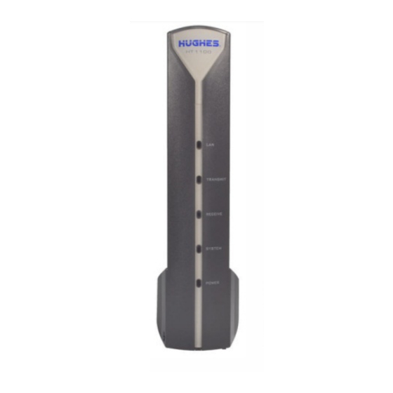
Chapter 3 LEDS Front panel LEDs The satellite modem has five LEDs on the front panel, as shown in Figure 16. By their appearance (on, off, blinking, or flashing) the LEDs indicate the modem's operating status. The front panel LEDs are blue when lit. Figure 16: Front panel LEDS Table 2 explains what the modem status is when the LEDs are on, off, or blinking. -
Page 22: Lan Port Leds
Table 2: Front panel LED indicators LEDS Appearance Status Satellite modem is connected to a computer network card or Ethernet device Blinking Transmitting and/or receiving data No device is connected to the LAN port Off* or the device connected to the LAN port is not working properly. - Page 23 Figure 17: LAN port LEDS Chapter 3 ● LEDS 1039650-0001 Revision A...
-
Page 25: Appendix A Standards Compliance
Appendix A Standards compliance The HT1100 satellite modem has been certified to comply with the standards listed in Table 3Table 3. Additional information follows the table. Table 3: HT100 standards compliance Category Standard UL60950-1 for the USA Safety CAN/CSA-C22.2 No. 60950-1 for Canada FCC Part 15 for the USA Electromagnetic Interference (EMI) - Page 26 Type of equipment: Two-way Hughes system Model number: HT1100 (1502573) Canada Class B w arning The two-way Hughes system (HT1100) complies with the Canadian ICES-003, Class B standard. Cet appareil numérique de la classe B est conforme á la norme NMB-003 du Canada.
-
Page 27: Acronyms And Abbreviations
Acronyms and abbreviations DHCP – Dynamic host configuration protocol NetBEUI – Extended User Interface (network transfer protocol) Networking requirements NOC – Network Operations Center ESN – Electronic serial number EMI – Electromagnetic interference SAN – Site account number FAP – Fair Access Policy VAR –... -
Page 29: Index
Index Built-In Self Test 18 Operating environment 8 heat sources 8 position 9 Center panel 14 Connectivity Test 16 Parameters bar 14 Description 7 Side panel 14 System Contol Center home page 11 Help 18 System Control Center 11 accessing 11 indicator links 12 System Information page 16 LEDs 21...
Need help?
Do you have a question about the Jupiter HT1100 and is the answer not in the manual?
Questions and answers