
Related Manuals for Hughes HN9800


Summary of Contents for Hughes HN9800
-
Page 1: Installation Guide
HN System HN9800 Satellite Modem Installation Guide 1039707-0001 Revision A April 10, 2013 11717 Exploration Lane, Germantown, MD 20876 Phone (301) 428-5500 Fax (301) 428-1868/2830... - Page 2 The information in this document is subject to change without notice. Hughes Network Systems, LLC makes no warranty of any kind with regard to this material, including, but not limited to, the implied warranties of merchantability and fitness for a particular purpose.
-
Page 3: Table Of Contents
Contents Understanding safety alert messages....7 Messages concerning personal injury ..... . 7 Messages concerning property damage . - Page 4 ground blocks ........18 Labeling the IFL cable ....... . 18 Hub or similar network device.
- Page 5 Specifications ........59 HN9800 modem specifications ......59 Appendix B Standards .
- Page 6 • Contents 1039707-0001 Revision A...
-
Page 7: Understanding Safety Alert Messages
Understanding safety alert messages Safety alert messages call attention to potential safety hazards and tell you how to avoid them. These messages are identified by the signal words DANGER, WARNING, CAUTION, or NOTICE, as illustrated below. To avoid possible property damage, personal injury, or in some cases possible death, read and comply with all safety alert messages. -
Page 8: Safety Symbols
Safety symbols The generic safety alert symbol calls attention to a potential personal injury hazard. It appears next to the DANGER, WARNING, and CAUTION signal words as part of the signal word label. Other symbols may appear next to DANGER, WARNING, or CAUTION to indicate a specific type of hazard (for example, fire or electric shock). -
Page 9: Satellite Modem Overview
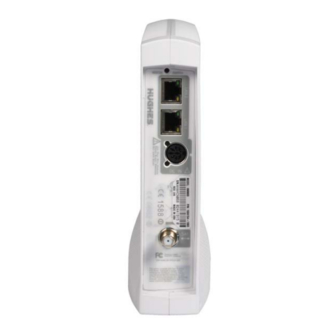
The HN9800 satellite modem provides Internet service by connecting a computer to a Ka-band bent-pipe satellite network. The modem’s Ethernet port connects to a computer or local area network (LAN). Figure 1 shows the HN9800 from the front and back. -
Page 10: Scope
Scope This installation guide explains how to install, commission, activate, and troubleshoot the HN9800 satellite modem. It also contains reference information to assist you in this process. Audience This guide is intended for professional installers. It may also be useful for: •... -
Page 11: Preparing For Installation
Chapter 2 Preparing for installation This chapter describes preparations for installing the satellite modem. Review this information before you install the satellite modem, antenna assembly, antenna mount, or inter-facility link (IFL) cable. To install the satellite modem, you need the Installation Reference Sheet, which contains installation parameters and other information specific to your site. -
Page 12: Installing The Satellite Modem
IFL cable. IFL cables For specific cable information see Table 2 on page 19. • Use only Hughes-approved cables. • Do not exceed maximum length for the outdoor unit (ODU) type, cable type, and cable part number. -
Page 13: Power Source
• For detailed information refer to the appropriate FSB, as listed in Table 2 on page 19. Items required for installation To install the HN9800 satellite modem, you need: • HN9800 satellite modem • Power supply (provided in the shipping carton) •... -
Page 14: Additional Equipment
• SAN and PIN - Identification numbers are required to register the satellite modem. Customers who purchased their system from a Hughes retail channel in the United States or Canada receive an order confirmation e-mail containing their site account number (SAN) and personal identification number (PIN). - Page 15 A suitable surge protector is recommended to protect the satellite modem from possible damage due to power surges. • Always connect the DC power cord to the HN9800 rear panel before applying power to the power supply. If you apply power to the power supply and then connect the DC power cord, the satellite modem may not perform properly and could be damaged.
-
Page 16: Computer And Networking Requirements
Computer requirements The HN9800 satellite modem can be used with any device that supports Internet Protocol (IP) and has a 10/100 BaseT Ethernet LAN port. Typically, the modem is connected to a customer's computer. However, the HN9800 is self-hosted; it does not require a computer for any of its functions. -
Page 17: Related Components
(RF) energy. The HN9800 satellite modem can be used with a 0.74 m, 0.98 m or 1.2 m two-way satellite antenna. The antenna assembly is shipped in a separate box. -
Page 18: Ground Blocks
Requirements for cables, connectors, and ground blocks You must use approved cable types and connectors to connect the modem to the outdoor satellite antenna. For grounding, you must use approved ground blocks and grounding connectors. For detailed specifications and information on these components, see the documents listed in Table 2 on page 19. - Page 19 You can view or download these documents at . Click https://dwayinstalls.hns.com/ on your installation support web site. If you cannot log in, Installer Login Click Here! contact your installer support for access to these documents. Table 2: Related installation documents Component or topic Where to find instructions Safety (all components) Site survey, Site...
- Page 20 Chapter 2 • Preparing for installation 1039707-0001 Revision A...
-
Page 21: Installing The Satellite Modem
Chapter 3 Installing the satellite modem Installation of the HN9800 satellite modem consists of physical installation followed by a highly automated process that fully prepares the modem for operation on the satellite network. Installation tasks include: • Physical installation and power-up •... -
Page 22: Ventilation And Heat Sources
Modem operating position Install and operate the HN9800 modem only in the upright vertical position resting on its built-in base as shown in Figure 5. Any other position could result in insufficient ventilation, overheating, and malfunction. -
Page 23: Powering Up The Modem
Powering up the modem For this task you must have the satellite modem and the correct power supply. To make sure you have the correct power supply, see Table 1 on page 16. Test the power outlet and power up the satellite modem: 1. -
Page 24: Connecting Your Laptop To The Modem
Connecting your laptop to the modem For this task you need an Ethernet cable to connect your laptop to the HN9800 modem. To access the satellite modem so you can perform the required installation procedures, you connect your laptop computer to the modem. -
Page 25: Connecting The Laptop
2. Select the options as shown in Figure 8. 3. Click Clear Now. Figure 8: Mozilla FireFox Clear All History screen. Connecting the laptop Connect your laptop to the modem: 1. Use an Ethernet cable to connect your laptop computer directly to the modem's LAN1 port, as shown in Figure 9. -
Page 26: Overview Of Entering Installation Parameters
• On some screens and in some messages you may see the word modem or the abbreviation VSAT. Both refer to the HN9800 satellite modem. • Screen and page are both used to refer to the information displayed on your computer monitor. -
Page 27: Entering Installation Parameters
Figure 11: Question mark Entering installation parameters 1. Open a browser on your laptop. Type The first http:://192.168.0.1. screen of the commissioning process displays. file determines the Input Params screens that appears. Figure 12 SBC.cfg shows the screen that allows you to select the satellite. Figure 12: Satellite selection screen Figure 13 shows the screen that allows you to select the transponder. - Page 28 Figure 13: Transponder selection screen 2. On the Input Params screen, click the format button you want to use to enter your parameters. 3. If you select the DD.MMM format, enter your parameters as shown in Figure 14. Figure 14: DD.MMM parameter option Some GPS receivers are suitable for Ka-band installations;...
- Page 29 6. If your select DD MM SS format, enter your parameters as shown in Figure 15. Figure 15: DD MM SS parameter option 7. Select Satellite or Transponder from the drop-down list. 8. Click Submit. The system displays the currently selected beam and an option to change the beam as shown Figure 16.
- Page 30 Figure 17: Beam error message 11. Select another beam from the drop-down list. 12. Click Submit. Once you click Submit, the satellite modem enters pointing mode. Refer to Chapter 4 – Installing outdoor equipment and antenna pointing on page 31 for the next step in the process.
-
Page 31: Installing Outdoor Equipment And Antenna Pointing
(including radio assemblies) and pointing, refer to the manuals listed in Table 2 on page 19. The HN9800 satellite modem can be used with a 0.74 m, 0.98 m or 1.2 m two-way satellite antenna. Assemble and install the antenna assembly according to the antenna installation manual. -
Page 32: Ifl Grounding Requirement
Figure 18: Connection of the DAPT2 For additional information on pointing and the DAPT2, see the Antenna Pointing Guide (1039429-0001). Note: The connectors on the DAPT2 are labeled IDU and LNB. If the cable from the satellite modem (the IDU) and the cable from the radio assembly on the antenna are connected to the wrong connectors, the DAPT2 will not receive a signal. -
Page 33: Connecting The Ifl Cable To The Modem
Connecting the IFL cable to the modem Connect the IFL cable to the connector on the rear panel of the modem as shown in Figure 19. Figure 19: All connections completed NOTICE The cable connector must be securely tightened. Make sure each connector is properly aligned (not cross-threaded). -
Page 34: Coarse And Fine Pointing
When the modem finishes downloading the pointing information, the DAPT2 displays a Pointing Done message. 3. Make sure you see the message on the DAPT2. Do not Pointing Done remove the DAPT2 until you see the Pointing Done. The following screens show the progression of pointing on the Terminal Installation screens. -
Page 35: Ranging
Ranging Ranging occurs when the HN9800 measures the distance to the satellite to calibrate transmit power and timing. Figure 22 shows ranging in progress. Figure 22: Ranging in progress Once ranging completes, the HN9800’s transmit and receive signal are synchronized to the satellite for optimal transport service. - Page 36 Chapter 4 • Installing outdoor equipment and antenna pointing 1039707-0001 Revision A...
-
Page 37: Commissioning And Registering The Satellite Modem
Chapter 5 Commissioning and registering the satellite modem During commissioning, the modem interacts with the satellite to establish transmit timing and synchronization. It interacts with the NOC for authentication and registration; and to obtain required software, security keys, and a preliminary configuration. -
Page 38: Registering The Terminal
and progresses until completion. Normally, there is no need for intervention. Figure 23 shows the commissioning tasks completed. Figure 23: Commissioning tasks completed Click Start Registration to proceed. Registering the terminal The next step in the process is activating or registering the terminal. The terminal registration process associates the SAN with the ESN. - Page 39 Figure 25: Registration conformation 4. Click Continue. 5. The system displays the registered for service screen Figure 26: Registration complete 6. Click Print this page to print a copy of the page or Continue to proceed. 7. The Registration page appears showing the status Installation complete. Chapter 5 •...
- Page 40 8. Click the Restart button. A pop-up window displays the message: Click on the button below to restart your HN9800. It make take a few seconds for the HN9800 to be Operational after restart. 9. Click the Restart button in the window.
-
Page 41: System Control Center
Chapter 6 System Control Center The System Control Center is a set of screens and links used to monitor the broadband service and troubleshoot the satellite modem in the event of a problem. The System Control Center provides access to system status, configuration information, and online documentation through a web browser on a computer connected to the satellite modem. -
Page 42: System Control Center Home Page
Getting Started - Through this link you can find general operating instructions for the HN9800 modem, recommended settings for your browser and TCP/IP, answers to frequently asked questions, and troubleshooting information. - Opens the Help page, which includes a variety of topics such as View Help Topics recommended browser and TCP/IP settings. -
Page 43: Common Features On System Control Center Screens
Common features on System Control Center screens Certain features are common to some or all of the System Control Center screens, as shown in Figure 30. These features are explained in the following sections. Figure 30: Common features on the System Control Center screens Button links At the top of each System Control Center page are four round buttons with labels above them as shown in Figure 31. -
Page 44: System Status Button
The destination page for each button link is identified below: Table 3: Button links on System Control Center screens Button Destination Description of destination page System Status System Status Page Displays general status information such as signal strength and commissioning status. System Status For more information see page... -
Page 45: Ipsec Icon
parameter listed next to the flagged value. If the parameter name is underlined, click the parameter name to see a message that may include helpful information, depending on what the problem is. IPSec icon An icon that looks like a small lock next to the System Status button means IPSec is enabled. -
Page 46: Small Icon On System Control Center Screens
• – Opens the Download Allowance Status screen, Download Allowance Status which shows how much remains of the daily download allowance. • – Opens the Help page, which includes a variety of topics such as getting Help started and recommended browser settings. Small icon on System Control Center screens The icon indicated by the arrow in the following illustration opens the Advanced Pages. -
Page 47: Red Flag Indicator
On any of these screens, if a parameter name or the current value of a parameter is underlined, you can click the name or value to see an explanation of it. Figure 34: Format of status and information screens Refer to sections below for an explanation for the parameters unique to each screen. •... -
Page 48: System Status Page
• Port Forwarding • Download Allowance Status • Browsing Optimization Utility System Status page The System Status page displays important information about the satellite modem’s operational status. The System Status page displays important information about the satellite modem’s operational status. Available system status values may vary, depending on how the satellite modem is configured. -
Page 49: Reception Information Page
Reception Information page The Reception Information page shown in Figure 36 displays information about data received by the satellite modem. Figure 36: Reception Information page The following table explains the parameters listed on the Reception Information page. Table 5: Reception Information page parameters Parameter Explanation Receive Status... - Page 50 The following illustration shows how you can view a list of all RxCodes or see an explanation of the currently displayed RxCode. Each RxCode–except RxCode 5–indicates a specific problem in the receive path. Figure 37: Finding additional Receive Status information The next illustration shows a sample list of RxCodes.
-
Page 51: Transmission Information Page
Transmission Information page The Transmission Information page shown in Figure 39 displays information about data transmissions from the satellite modem. Figure 39: Transmission Information page The following table gives an explanation of the parameters on the Transmission Information page. Table 6: Transmission Information page parameters Parameter Explanation Transmit Status... - Page 52 The following illustration shows how you can view a list of all TxCodes or see an explanation of the currently displayed TxCode. Each TxCode—except TxCode 8—indicates a specific problem in the transmission path. Figure 40: Finding additional Transmit Status information Chapter 6 •...
-
Page 53: System Information Page
System Information page The System Information page shown in Figure 41 provides system information for the satellite modem such as Site ID and the release number of the modem’s operational software. Figure 41: System Info page Help page The System Control Center Help page (Figure 42) contains information to help the user get started in using the satellite modem, find contact information for assistance, and other helpful information. - Page 54 Figure 42: Help page Chapter 6 • System Control Center 1039707-0001 Revision A...
-
Page 55: Leds
(on, off, blinking, or flashing) the LEDs indicate the modem's operating status. The front panel LEDs are all blue when lit. Figure 43: Front panel LEDS on the HN9800 Table 7 explains what the modem status is when the LEDs are on, off, or blinking. On means the LED is continuously lit. - Page 56 intermittently turns off briefly. Flashing means the LED alternates between on and off for periods of ½ sec to 1 sec. Table 7: Front panel LED indications Appearance Status Satellite modem is connected to a computer network card or Ethernet device Blinking Transmitting and/or receiving data Off*...
-
Page 57: Lan Port Leds
LAN port LEDs Green and orange LEDs on the LAN (Ethernet) port on the modem's rear panel indicate link status and speed, as explained in Figure 44. Figure 44: LAN port LEDs Chapter 7 • LEDS 1039707-0001 Revision A... - Page 58 Chapter 7 • LEDS 1039707-0001 Revision A...
-
Page 59: Specifications
Appendix A Specifications HN9800 modem specifications Table 8: Specifications for the HN9800 Weight 1.6 lb (0.73 kg) Height 8.0 inches (20.3 cm) Width 1.6 inches (4.1 cm); 2.4 inches (6.1 cm) at base Depth 9.0 inches (22.9 cm) Operating temperature range 41 °F to 104 °F (5 °C to... - Page 60 Appendix A • Specifications 1039707-0001 Revision A...
-
Page 61: Standards
Appendix B Standards The HN9800 satellite modem has been certified to comply with the standards listed in Table 9. Additional information follows the table. Table 9: HN9800 standards compliance Category Standard Safety UL60950-1 for the USA, International CAN/CSA-C22.2 No. 60950-1 for Canada... -
Page 62: Electromagnetic Interference (Emi)
FCC Part 15 This section applies to the HN9800 satellite modem. Standards to which conformity is declared: FCC Part 15 The modem complies with Part 15 of the FCC Rules. Operation is subject to the... -
Page 63: Acronyms And Abbreviations
Acronyms and abbreviations AC - Alternating current ODU - Outdoor unit CAN – Canada PIN - Personal identification number CSA – Canadian Standards Association RF - Radio frequency DAPT - DiSEqC antenna pointing tool SAN - Site account number EMI – Electromagnetic Interference EU –... - Page 64 • Acronyms and abbreviations 1039707-0001 Revision A...
-
Page 65: Index
Index items required 13 preparing for 11 Advanced Pages 46 summary 11 Antenna Installation parameters course pointing 34 entering 27 pointing 33 overview 26 ranging 35 Installation Reference Sheet 13 related documents 19 IPSec 45 Button links on System Control Center pages 43 LEDs front panel 55 LAN port 55, 57... - Page 66 SAN 14 Site survey 12, 14, 19 System Control Center Reception Information page 49 System Status button colors 44 System Status page 48 Transmission Information page 51 System Information page 53 System Status button colors 44 System Status page 44 Transmission Information page 51 Transmit status 51 TXCodes 52...
Need help?
Do you have a question about the HN9800 and is the answer not in the manual?
Questions and answers