
Related Manuals for Hughes JUPITER System HT2000


Summary of Contents for Hughes JUPITER System HT2000
- Page 1 HT2000 Satellite Modem User Guide 1040967-0001 Revision A November 1, 2016 11717 Exploration Lane, Germantown, MD 20876 Phone (301) 428-5500 Fax (301) 428-1868/2830...
- Page 2 Hughes Network Systems, LLC has made every effort to ensure the correctness and completeness of the material in this document. Hughes Network Systems, LLC shall not be liable for errors contained herein. The information in this document is subject to change without notice.
-
Page 3: Table Of Contents
Contents Understanding safety alert messages ............ 5 Messages concerning personal injury ..............5 Messages concerning property damage ..............5 Safety symbols ....................... 6 Additional symbols ................... 6 Chapter 1 Satellite modem overview ..............7 Description ......................7 Operating environment ..................8 Ventilation and heat sources ................ - Page 4 Canada Class B warning .................. 24 Class II Radio Equipment (per R&TTE Directive 1999/5/EC) ......25 Acronyms ....................29 Index ....................31 Contents 1040967-0001 Revision A...
-
Page 5: Understanding Safety Alert Messages
Understanding safety alert messages Safety alert messages call attention to potential safety hazards and tell you how to avoid them. These messages are identified by the signal words DANGER, WARNING, CAUTION, or NOTICE, as illustrated below. To avoid possible property damage, personal injury, or in some cases possible death, read and comply with all safety alert messages. -
Page 6: Safety Symbols
Safety symbols The generic safety alert symbol calls attention to a potential personal injury hazard. It appears next to the DANGER, WARNING, and CAUTION signal words as part of the signal word label. Other symbols may appear next to DANGER, WARNING, or CAUTION to indicate a specific type of hazard (for example, fire or electric shock). -
Page 7: Satellite Modem Overview
Chapter 1 Satellite modem overview This user guide describes the features and operation of the HT2000 satellite modem, which provides Internet access by satellite. In this user guide, satellite modem and modem both refer to the HT2000 satellite modem. Description The HT2000 satellite modem connects to a satellite network to provide Internet service. -
Page 8: Operating Environment
Do not press the reset/rescue button on the HT2000 unless a customer service representative tells you to do so. The USB port is provided to support a future modem feature. Hughes does not recommend plugging anything into this port at this time. Hughes will inform you when this feature is available. -
Page 9: Operating Position
Operating position Operate the HT2000 modem only in an upright, vertical position, resting on its built-in base, as shown in Figure 2. Any other position could result in insufficient ventilation, overheating, and malfunction. Figure 2: Modem operating position Computer requirements The computer that connects to the satellite modem should meet the minimum requirements specified by the computer operating system manufacturer and the following networking and browser requirements. -
Page 10: Contact Information
Contact information If you need operational, warranty, or repair support, who you should contact depends on where you purchased your satellite modem. Please contact your customer service representative (CSR) in accordance with your service agreement. Power supply information Always use the power supply provided with the satellite modem. The modem's performance may suffer if the wrong power supply is used. -
Page 11: Connecting The Modem Power Cord
Connecting the modem power cord The HT2000 power cord connector uses a locking mechanism to ensure it stays snugly connected to the modem. Make sure the connector is oriented correctly when plugging it into the DC IN port. Figure 3 explains how to correctly orient the power cord connector. - Page 12 When removing the power cord, brace the modem with one hand. Use your other hand to slide the power connector sleeve toward you (away from the modem) and pull the power cord from the DC IN port. See Figure Important: If the power cord does not easily disconnect from the DC IN port, do not force it.
-
Page 13: System Control Center
Chapter 2 System Control Center The System Control Center is a set of screens and links you can use to monitor your service and troubleshoot the satellite modem in the event of a problem. The System Control Center provides access to system status, configuration information, and online documentation. -
Page 14: Indicator Links
Indicator links At the top of each System Control Center page are two indicators followed by a text link (Figure 7), as well as a language selection drop-down. Figure 7: Indicators and links Each text link navigates to a page in the System Control Center. Table 1 describes the destination page for each link. -
Page 15: Side Panel
Side panel The following links appear on the left side panel of each System Control Center screen as shown in Figure Figure 9: Side panel links Home – Opens the System Control Center home page. Connectivity Test – Opens the Connectivity Test page, which you can use to test the connection between the satellite modem and the NOC. -
Page 16: System Status Page
System Status page The System Status page lists parameter information vital to the proper operation of the HT2000. Available system status values (as shown in Figure 10) may vary, depending on how your satellite modem is configured. Figure 10: System Status page Chapter 2 ●... -
Page 17: System Information Page
System Information page The System Information page (shown in Figure 11) provides system information for the satellite modem, such as identification information, software versions, and satellite information. Figure 11: System Information page Connectivity test To test your connectivity: 1. Click the Connectivity Test link on the side panel. The Terminal/Gateway Connectivity Test panel appears in the center of the screen. -
Page 18: Built-In Self Test
4. When the test completes, the results appear in the center panel. Figure 13 shows the results of the test. Figure 13: Connectivity test results Built-in self test Use the Built-In Self Test link on the side panel to check the connectivity of the satellite modem. -
Page 19: Chapter 3 Leds
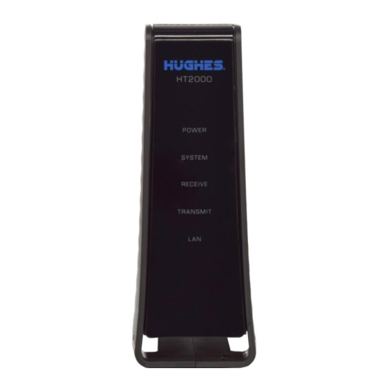
Chapter 3 LEDS Front-panel LEDs The satellite modem has five LEDs on the front panel, as shown in Figure 15. By their appearance (on, off, blinking, or flashing) the LEDs indicate the modem's operating status. The front-panel LEDs are white when lit. POWER –... -
Page 20: Lan Port Leds
Table 2: Modem status LEDs LEDS Appearance Status Satellite modem is connected to a computer network card or Ethernet device. Blinking Transmitting and/or receiving data. No device is connected to the LAN port, or the device Off* connected to the LAN port is not working properly. OK - Transmit path is operational. -
Page 21: Appendix A Specifications
Appendix A Specifications HT2000 modem specifications The specifications for the HT2000 modem are listed in Table Table 3: HT2000 modem specifications Item Specifications Weight 1.071lb (0.486 kg) Height 7.28 inches (184.92 mm) Width 2.766 inches (70.26 mm) Depth 5.822 inches (147.88 mm) Operating temperature range 41 °F to 104 °F (5 °C to 40 °C) Above 5,000 ft (1,524 m) altitude, the maximum... -
Page 23: Appendix B Standards Compliance
Appendix B Standards compliance The HT2000 satellite modem has been certified to comply with the standards listed Table 4. Additional information follows the table. Table 4: HT2000 standards compliance Category Standard UL60950-1 for the USA CAN/CSA-C22.2 No. 60950-1 for Canada Safety IEC60950-1 for International (CB Scheme Certification) -
Page 24: Fcc Part 15
(1) This device may not cause harmful interference, and (2) this device must accept any interference received, including interference that may cause undesired operation. Responsible party's name: Hughes Network System, LLC Address: 11717 Exploration Lane, Germantown, MD 20876 Telephone: 1 (866) 347-3292... -
Page 25: Class Ii Radio Equipment (Per R&Tte Directive 1999/5/Ec)
Switzerland Bulgaria Romania Statement on compliance with the R&TTE Directive 1999/5/EC Hereby, Hughes declares that this Class II Radio Equipment is in compliance with the essential requirements and other English relevant provisions of Directive 1999/5/EC. Hughes, vakuuttaa täten että Luokka II radiolaitteet tyyppinen laite on direktiivin 1999/5/EY oleellisten vaatimusten ja sitä... - Page 26 Équipement de classe est conforme aux exigences essentielles et aux autres dispositions pertinentes de la directive 1999/5/CE French Par la présente, Hughes déclare que ce II Radio Équipement de classe est conforme aux exigences essentielles et aux autres dispositions de la directive 1999/5/CE qui lui sont applicables Härmed intygar Hughes att denna Klass II radioutrustning står...
- Page 27 Italian apparecchiature radio è conforme ai requisiti essenziali ed alle altre disposizioni pertinenti stabilite dalla direttiva 1999/5/CE. Por medio de la presente Hughes declara que el Clase II Radio Equipment cumple con los requisitos esenciales y cualesquiera Spanish otras disposiciones aplicables o exigibles de la Directiva 1999/5/CE Hughes declara que este II Radio Equipment classe está...
-
Page 29: Acronyms
Acronyms AC – Alternating current ICES – Institute for Clinical Evaluative Sciences IP – Internet Protocol IPoS – IP over Satellite BIST – Built-in self test LAN – Local area network LED – Light emitting diode CSA – Canadian Standards Association (Canada) CSR –... -
Page 31: Index
Index Modem power supply 10 connecting power cord to modem 11 disconnecting power cord from modem 11 Computer requirements 9 Modem specifications 21 Internet browser 9 networking 9 Standards compliance 23 Support 10 Front-panel LEDs 19 System Control Center 13 accessing 13 built-in self test 18 connectivity test 17...
Need help?
Do you have a question about the JUPITER System HT2000 and is the answer not in the manual?
Questions and answers