
Related Manuals for Hughes HT1000


Summary of Contents for Hughes HT1000
-
Page 1: Installation Guide
HT1000 Satellite Modem Installation Guide 1039110-0001 Revision A October 17, 2012 11717 Exploration Lane, Germantown, MD 20876 Phone (301) 428-5500 Fax (301) 428-1868/2830... - Page 2 The information in this document is subject to change without notice. Hughes Network Systems, LLC makes no warranty of any kind with regard to this material, including, but not limited to, the implied warranties of merchantability and fitness for a particular purpose.
-
Page 3: Table Of Contents
Contents Understanding safety alert messages....7 Messages concerning personal injury ..... . 7 Messages concerning property damage . - Page 4 ground blocks ........17 Labeling the IFL cable ....... . 18 Hub or similar network device.
- Page 5 Specifications ........83 HT1000 modem specifications......83 Appendix B Standards .
- Page 6 • Contents 1039110-0001 Revision A...
-
Page 7: Understanding Safety Alert Messages
Understanding safety alert messages Safety alert messages call attention to potential safety hazards and tell you how to avoid them. These messages are identified by the signal words DANGER, WARNING, CAUTION, or NOTICE, as illustrated below. To avoid possible property damage, personal injury, or in some cases possible death, read and comply with all safety alert messages. -
Page 8: Safety Symbols
Safety symbols The generic safety alert symbol calls attention to a potential personal injury hazard. It appears next to the DANGER, WARNING, and CAUTION signal words as part of the signal word label. Other symbols may appear next to DANGER, WARNING, or CAUTION to indicate a specific type of hazard (for example, fire or electric shock). -
Page 9: Satellite Modem Overview
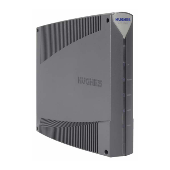
The HT1000 satellite modem provides Internet service by connecting a computer to a Ka-band bent-pipe satellite network. The modem’s Ethernet port connects to a computer or local area network (LAN). Figure 1 shows the HT1000 from the front and back. -
Page 10: Scope
• Installer Support refers to organizations that provide assistance to professional installers of Hughes satellite equipment. If you do not know who provides your support, contact Hughes dealer services. Scope This installation guide explains how to install, commission, activate, and troubleshoot the HT1000 satellite modem. -
Page 11: Preparing For Installation
Chapter 2 Preparing for installation This chapter describes preparations for installing the satellite modem. Review this information before you install the satellite modem, antenna assembly, antenna mount, or inter-facility link (IFL) cable. To install the satellite modem, you need the Installation Reference Sheet, which contains installation parameters and other information specific to your site. -
Page 12: Installing The Satellite Modem
IFL cable. IFL cables For specific cable information see Table 2 on page 18. • Use only Hughes-approved cables. • Do not exceed maximum length for the outdoor unit (ODU) type, cable type, and cable part number. -
Page 13: Power Source
• For detailed information refer to the appropriate FSB, as listed in Table 2 on page 18. Items required for installation To install the HT1000 satellite modem, you need: • HT1000 satellite modem • Power supply (provided in the shipping carton) •... -
Page 14: Additional Equipment
• SAN and PIN - Identification numbers are required to register the satellite modem. Customers who purchased their system from a Hughes retail channel in the United States or Canada receive an order confirmation e-mail containing their site account number (SAN) and personal identification number (PIN). - Page 15 A suitable surge protector is recommended to protect the satellite modem from possible damage due to power surges. • Always connect the DC power cord to the HT1000 rear panel before applying power to the power supply. If you apply power to the power supply and then connect the DC power cord, the satellite modem may not perform properly and could be damaged.
-
Page 16: Computer And Networking Requirements
Computer requirements The HT1000 satellite modem can be used with any device that supports Internet Protocl (IP) and has a 10/100 BaseT Ethernet LAN port. Typically, the modem is connected to a customer's computer. However, the HT1000 is self-hosted; it does not require a computer for any of its functions. -
Page 17: Related Components
(RF) energy. The HT1000 satellite modem can be used with a 0.69 m, 0.74 m, or 0.98 m, two-way satellite antenna. The antenna assembly is shipped in a separate box. -
Page 18: Labeling The Ifl Cable
The coaxial IFL cable and the ground block to which they are connected must meet the grounding requirements specified in the following warning: WARNING You must comply with applicable local codes and the grounding requirements in Field Service Bulletin (FSB), HNS Broadband Requirements for RG-6 and RG-11 IFL Cable Connectors, Ground Blocks, and Ground Block Location (FSB_050518_01). - Page 19 Where to find instructions IFL Cable IFL cables (specifications, approved types, Field Service Bulletin (FSB), Approved List (with lengths) for maximum lengths) Jupiter/HT1000/HT1100 Domestic Installations (FSB_0120909_01). IFL cable connectors, Grounding, Ground HNS Broadband Requirements for RG-6 blocks and RG-11 IFL Cable Connectors, Ground...
- Page 20 Chapter 2 • Preparing for installation 1039110-0001 Revision A...
-
Page 21: Installing The Satellite Modem
Chapter 3 Installing the satellite modem Installation of the HT1000 satellite modem consists of physical installation followed by a highly automated process that fully prepares the modem for operation on the satellite network. Installation tasks include: • Physical installation and power-up •... -
Page 22: Ventilation And Heat Sources
Modem operating position Install and operate the HT1000 modem only in the upright vertical position resting on its built-in base as shown in Figure 5. Any other position could result in insufficient ventilation, overheating, and malfunction. -
Page 23: Powering Up The Modem
Powering up the modem For this task you must have the satellite modem and the correct power supply. To make sure you have the correct power supply, see Table 1 on page 16. Test the power outlet and power up the satellite modem: 1. -
Page 24: Connecting Your Laptop To The Modem
Connecting your laptop to the modem For this task you need an Ethernet cable to connect your laptop to the HT1000 modem. To access the satellite modem so you can perform the required installation procedures, you connect your laptop computer to the modem. -
Page 25: Connecting The Laptop
2. Select the options as shown in Figure 8. 3. Click Clear Now. Figure 8: Mozilla FireFox Clear All History screen. Connecting the laptop Connect your laptop to the modem: 1. Use an Ethernet cable to connect your laptop computer directly to the modem's LAN port, as shown in Figure 9. -
Page 26: Overview Of Entering Installation Parameters
• On some screens and in some messages you may see the word modem or the abbreviation VSAT. Both refer to the HT1000 satellite modem. • Screen and page are both used to refer to the information displayed on your computer monitor. - Page 27 2. The System Control Center home page appears as shown in Figure 11. Figure 11: System Control Center home page 4. Click the Advanced Pages icon at the top of the page as shown in Figure 12. The Advanced Configuration and Statistics page appears as shown in Figure 13. Figure 12: Advanced pages icon Chapter 3 •...
- Page 28 Figure 13: Advanced Configuration and Statistics page Chapter 3 • Installing the satellite modem 1039110-0001 Revision A...
- Page 29 3. Click Installation on the side panel to access the drop-down menu as shown in Figure 14. Figure 14: Advanced Pages Install link 4. Click the Install link to begin the installation. The Input Params screen appears as shown in Figure 15. Figure 15: Terminal Installation screen - Input Params Chapter 3 •...
-
Page 30: Entering Installation Parameters
Entering installation parameters 1. On the Input Params screen enter the Latitude and Longitude from your GPS as shown in Figure 16. Figure 16: Latitude and longitude parameters 2. Enter the site latitude and longitude values from your Global Positioning System (GPS) receiver, in degrees and minutes to three decimal places. - Page 31 Refer to Chapter 4 – Installing outdoor equipment and antenna pointing on page 33 for the next step in the process. Chapter 3 • Installing the satellite modem 1039110-0001 Revision A...
- Page 32 Chapter 3 • Installing the satellite modem 1039110-0001 Revision A...
-
Page 33: Installing Outdoor Equipment And Antenna Pointing
(including radio assemblies) and pointing, refer to the manuals listed in Table 2 on page 18. The HT1000 satellite modem can be used with a 0.69 m, 0.74 m, or 0.98 m two-way satellite antenna. Assemble and install the antenna assembly according to the antenna installation manual. -
Page 34: Ifl Grounding Requirement
Figure 17: Connection of the DAPT2 For additional information on pointing and the DAPT2, see the Jupiter Antenna Pointing Guide (1039429-0001). Note: The connectors on the DAPT2 are labeled IDU and LNB. If the cable from the satellite modem (the IDU) and the cable from the radio assembly on the antenna are connected to the wrong connectors, the DAPT2 will not receive a signal. -
Page 35: Connecting The Ifl Cable To The Modem
Connecting the IFL cable to the modem Connect the IFL cable to the connector on the rear panel of the modem as shown in Figure 18. Figure 18 shows the placement of all connections. Figure 18: All connections completed NOTICE The cable connector must be securely tightened. -
Page 36: Coarse And Fine Pointing
The Pointing Validation screen (Figure 19) shows the validation in progress. Ranging Ranging occurs when the HT1000 measures the distance to the satellite to calibrate transmit power and timing. Once ranging is complete the HT1000’s transmit and receive signal are synchronized to the satellite for optimal transport service. - Page 37 1. Remove the DAPT2 and connect the IFL cable from the satellite modem to the radio assembly. At this point the modem automatically begins the process of commissioning which includes registering with the NOC, and related activities. 2. Go back inside to complete installation of the modem. Chapter 4 •...
- Page 38 Chapter 4 • Installing outdoor equipment and antenna pointing 1039110-0001 Revision A...
-
Page 39: Registering And Commissioning The Satellite Modem
Chapter 5 Registering and commissioning the satellite modem During commissioning, the modem interacts with the satellite to establish transmit timing and synchronization. It interacts with the NOC for authentication and registration; and to obtain required software, security keys, and a preliminary configuration. - Page 40 Figure 20 shows the registration process in progress with several other activities underway. The activities occur in the order they are listed on the screen, top to bottom. Figure 20: Processes in progress and completed Once the registration in complete, the Configuration process begins automatically. Figure 21 shows Ranging, Registration, and Associating with Network are done.
-
Page 41: Validating The Installation
Chapter 6 Validating the installation As part of every HT1000 installation you are required to validate the overall installation (modem, antenna, cables, and connections) using the Ka-band Onsite Validation Tool (OVT). This browser-based tool helps to ensure a high-quality installation. If the site performance is not satisfactory, the OVT suggests corrective actions you can take and then analyzes the results of your actions. - Page 42 Figure 22: Onsite Validation Tool link Note: Hughes installers will connect to the HughesNet Installation Portal. If you are a VAR you may have a different way to access the OVT and validate the installation. Please refer to your VAR procedures.
- Page 43 The HughesNet Installation Portal login screen opens, as shown in Figure 23. Figure 23: Installation Portal, installer login screen Log in to the Installation Portal: 1. Enter your Installer ID as the User Name. 2. Enter your Password. 3. Click LOGIN. The initial OVT screen appears as shown in Figure 24.
- Page 44 Figure 24: OVT initial screen 1. Select I have a Valid Hughes Service Order option. 2. Enter your San: 3. Enter your Service Order number. Launch 4. Click 5. The first OVT screen appears. Chapter 6 • Validating the installation...
- Page 45 Figure 25: OVT screen 1 1. Click the Refresh Site Info button to update the display. 2. Select the antenna size in Step 2 on the screen. 3. Choose the mount type in Step 3 on the screen. 4. Click Proceed. The second screen of the OVT appears as shown in Figure 26. Chapter 6 •...
- Page 46 Figure 26: OVT screen 2 5. The Diagnosis and Recommended Action fields at the bottom of the screen give you instructions on your next step. Once you have completed the recommended Signoff course of action, click the Completed Action button, then click the button.
- Page 47 6. Select the appropriate options describing your installation from categories displayed on the screen. You must enter a comment in the Provide Installation Details Below box before you click the Signoff button as shown in Figure 28. Figure 28: OVT Signoff screen. 7.
- Page 48 Chapter 6 • Validating the installation 1039110-0001 Revision A...
-
Page 49: Activating The Terminal
SAN with the ESN. 1. Make sure your laptop computer is connected to the modem's LAN port. 2. Click the HT1000 Registration tab at the top of the screen. 3. The installation home page appears, showing the link. - Page 50 Figure 30: Activation screen 6. Enter the SAN and PIN. The SAN and PIN are provided on the customer's Order Continue. Confirmation email and on the Installation Reference Sheet. Click 7. After the SAN and PIN information is entered and validated, a screen appears that includes the customer's name and other details as shown in Figure 31.
-
Page 51: Chapter 8
Figure 32: Successful activation screen Proceed to Chapter 8 – Activating the HughesNet service for the next step in the process. Chapter 7 • Activating the terminal 1039110-0001 Revision A... - Page 52 Chapter 7 • Activating the terminal 1039110-0001 Revision A...
-
Page 53: Activating The Hughesnet Service
Chapter 8 Activating the HughesNet service Activating the HughesNet broadband service is the final step in installing the satellite modem. The customer performs this step, and at the same time accepts the HughesNet subscriber agreement. You prepare the customer for activation by connecting the satellite modem to the customer's computer. - Page 54 2. The System Status screen appears. Ensure that all downloads are complete as indicated by the green check marks following the procedures or tasks as show in Figure 34. Figure 34: System Status screen 3. Click the link on the side panel. The System Control home page appears as Home shown in Figure 35.
-
Page 55: Service Activation Prerequisites
Link Figure 35: System Control Center home page 4. Notice you have a Service Activation link on the side panel. Do not click this link at this time. Before you activate the customer’s service, you must connect the customer’s computer to the satellite modem. Service activation prerequisites Before proceeding, make sure the modem and the customer's computer are ready for service activation. -
Page 56: Activation Procedure
Note: If the customer wants to connect the modem to a router, do not connect the until activation is complete. Figure 36: Connecting Ethernet cable to customer’s computer Activation procedure The customer activates the HughesNet service. A summary of the activation process is provided here, so that you will know what the customer should expect. - Page 57 3. The Welcome HughesNet Member! screen appears as shown in Figure 37. Figure 37: Welcome to HughesNet screen 4. Click the I accept the Terms and Conditions box. 5. Click Continue. Chapter 8 • Activating the HughesNet service 1039110-0001 Revision A...
- Page 58 6. The Account Registration screen appears as shown in Figure 38. Figure 38: Account Registration screen 7. Click the link. Register 8. The email account screen appears as shown in Figure 39. Chapter 8 • Activating the HughesNet service 1039110-0001 Revision A...
- Page 59 Figure 39: Email account screen The customer has the option of using an existing account or creating a HughesNet email account. Ask them to click the box for their choice. Chapter 8 • Activating the HughesNet service 1039110-0001 Revision A...
- Page 60 If the customer elects to sign up for a HughesNet email account, they will be presented with a series of screens to create and verify account as shown in Figure 40. Figure 40: Email screens Submit 9. The customer should complete each field and click the button.
-
Page 61: Digital Life Now Download
11. The Welcome to HughesNet screen appears as shown in Figure 42. Figure 42: Welcome to HughesNet screen Digital Life Now download Figure 42 describes the benefits of using Digital Life Now. If the customer wants the service, the customer should click the Download button to start the download. The Download Digital Life Now screen appears as shown in Figure 43. - Page 62 Figure 43: Digital Life screen. 12. On the download screen the customer should click Continue. 13. If the customer selected No Thanks, the customer will be directed to the Basic Status Meter screen as show in Figure 44. Figure 44: Basic Status Meter screen Chapter 8 •...
- Page 63 14. The customer should select Yes, Install Now to start the service or No Thanks if the service is not wanted. The system displays the a pop-up window as shown in Figure 45. Ask the customer to select the bottom for their choice. Figure 45: Status Meter conformation screen 15.
- Page 64 18. Once the install completes for the Digital Life Now or the Status Meter, the You are almost set screen appears as shown in Figure 48. Figure 48: Almost set screen Exit 19. Instruct the customer to click to access the web page.
-
Page 65: System Control Center
Chapter 9 System Control Center The System Control Center is a set of screens and links used to monitor the broadband service and troubleshoot the satellite modem in the event of a problem. The System Control Center provides access to system status, configuration information, and online documentation through a web browser on a computer connected to the satellite modem. - Page 66 Figure 49 shows the System Control Center home page before activation. Notice that the System Status indicator is red which means that system requires attention. Refer to Indicator links on page 67 for more additional information about indicator links. Figure 49: System Control Center home page before activation Figure 50 shows the System Control Center home page after activation.
-
Page 67: Indicator Links
Status indicator. Figure 52: System Status indicator colors and meanings Note: Hughes maintains a Fair Access Policy (FAP). This policy establishes an equitable balance in Internet access for all HughesNet subscribers. Hughes assigns a Download Allowance to each service plan that limits the amount of data that may be continuously downloaded within specified time periods. -
Page 68: Parameters Bar
The table below identifies the destination page for each link Table 3: Destination pages Indicator Destination Description System Status System Status page Gives important information about the satellite modem’s operational status. System Information System Information page General information screen that identifies software and hardware versions, and satellite connection information. -
Page 69: Center Panel Text Links And Information
Center panel text links and information The System Control Center home page center panel includes the following text links and informational panels once service is activated: Figure 54: System Control Center Help panel HELP area - HughesNet Web Portal contains a variety of useful tools, Welcome to HughesNet resources, and information. -
Page 70: Side Panel
Side panel The following links appear on the left panel of each System Control Center screen as shown in Figure 55. Figure 55: Side panel links - Opens the System Control Center home page. Home - Opens the Connectivity Test page, which you can use to test the Connectivity Test connection between the satellite modem and the NOC. -
Page 71: System Status Page
System Status page The System Status page lists parameter information vital to the proper operation of the HT1000. Available system status values (as shown in Figure 57) may vary, depending on how the satellite modem is configured. Figure 57: System Status page Chapter 9 •... -
Page 72: System Information Page
System Information page The System Information page, shown in Figure 58, provides system information for the satellite modem such as identification information, software versions, and satellite information. Figure 58: System Information page Chapter 9 • System Control Center 1039110-0001 Revision A... -
Page 73: Leds
(on, off, blinking, or flashing) the LEDs indicate the modem's operating status. The front panel LEDs are all blue when lit. Figure 59: Front panel LEDS on the HT1000 Table 4 explains what the modem status is when the LEDs are on, off, or blinking. On means the LED is continuously lit. - Page 74 intermittently turns off briefly. Flashing means the LED alternates between on and off for periods of ½ sec to 1 sec. Table 4: Front panel LED indications Appearance Status Satellite modem is connected to a computer network card or Ethernet device Blinking Transmitting and/or receiving data Off*...
-
Page 75: Lan Port Leds
LAN port LEDs Green and orange LEDs on the LAN (Ethernet) port on the modem's rear panel indicate link status and speed, as explained in Figure 60. Figure 60: LAN port LEDs Chapter 10 • LEDS 1039110-0001 Revision A... - Page 76 Chapter 10 • LEDS 1039110-0001 Revision A...
-
Page 77: Advanced Pages
Chapter 11 Advanced Pages The Advanced Configuration and Statistics pages, also known as the Advanced Pages, contain a great deal of detailed information about the satellite modem including statistics, diagnostic information, logs, status, and operating parameters. You may need to access the Advanced Pages to find specific information or to configure special features. -
Page 78: Expanding And Collapsing Menus
Figure 62: Advanced Pages example showing the advanced menu Expanding and collapsing menus To expand the Advanced Menu on the left side of the screen to show additional selections, click a menu item. If you expand another menu item, the previously expanded menu item collapses. -
Page 79: State Codes
Figure 63: Installation sub-menu State codes The terminal state code provides a hierarchical representation of the current status of the satellite modem. The state code displays on the System Status page as shown in Figure 64. Chapter 11 • Advanced Pages 1039110-0001 Revision A... - Page 80 State Code Figure 64: System Status page showing State Code To access the State Code monitor page: 1. Access the Advanced Configuration and Statistics page. 2. Expand the General menu item. 3. Click . The State Code Monitor page appears as shown in State Code Monitor Figure 65.
- Page 81 Figure 65: State Code Monitor page The State Code Monitor page provides: • Current system state code. • The current state code per component /process. • Overview of the terminal since startup and the total duration in seconds for each state code.
- Page 82 Chapter 11 • Advanced Pages 1039110-0001 Revision A...
-
Page 83: Specifications
Appendix A Specifications HT1000 modem specifications Table 5: Specifications for the HT1000 Weight 1.6 lb (0.73 kg) Height 8.0 inches (20.3 cm) Width 1.6 inches (4.1 cm); 2.4 inches (6.1 cm) at base Depth 9.0 inches (22.9 cm) Operating temperature range 41 °F to 104 °F (5 °C to... - Page 84 Appendix A • Specifications 1039110-0001 Revision A...
-
Page 85: Standards
Appendix B Standards The HT1000 satellite modem has been certified to comply with the standards listed in Table 6. Additional information follows the table. Table 6: HT1000 standards compliance Category Standard Safety UL60950-1 for the USA CAN/CSA-C22.2 No. 60950-1 for Canada... -
Page 86: Electromagnetic Interference (Emi)
FCC Part 15 This section applies to the HT1000 satellite modem. Standards to which conformity is declared: FCC Part 15 The modem complies with Part 15 of the FCC Rules. Operation is subject to the... -
Page 87: Acronyms And Abbreviations
Acronyms and abbreviations OVT - Onsite Validation Tool AC - Alternating current PIN - Personal identification number DAPT - DiSecQ antenna pointing tool RF - Radio frequency RHCP - Right-handed circular polarization EMI - Electromagnetic interference SAN - Site account number FAP –... - Page 88 • Acronyms and abbreviations 1039110-0001 Revision A...
-
Page 89: Index
Index Activation IFL cable 12, 13, 17, 18, 19, 33, 34 HughesNet 53 Installation procedures 56 checklist 12 Subscriber Agreement 49 items required 13 Advanced Pages preparing for 11 accessing 77 summary 11 Advanced Configuration and Statistics Installation parameters page 28 entering 30 expanding menus 78 install link 29... - Page 90 SAN 14, 50 Site survey 12, 14, 18 State code 79 System Control Center accessing 65 Help 69 home page 27, 65 icon 70 indicator links 67 links 69, 70 parameters bar 68 Status page 71 System Information page 71 Terminal Installation screen screen parts 29 •...
Need help?
Do you have a question about the HT1000 and is the answer not in the manual?
Questions and answers