Table of Contents
Advertisement
Advertisement
Table of Contents

Related Manuals for 2N IP Force 9151101W


Summary of Contents for 2N IP Force 9151101W
- Page 1 Installation manual 2N® IP Force v.2.18 www.2n.com...
-
Page 2: Table Of Contents
Installation manual 2N® IP Force Content: • 1. Product Overview • 1.1 Components and Associated Products • 1.2 Terms and Symbols • 2. Description and Installation • 2.1 Before You Start • 2.2 Mechanical Installation • 2.3 Electric Installation •... -
Page 3: Product Overview
IP PBX and telephone ® ® suppliers, 2N IP Force can make use of all VoIP services. 2N IP Force can work as a standard or emergency door access intercom for buildings, entrances to premises or garages, manufacturing halls, highways and so on. -
Page 4: Components And Associated Products
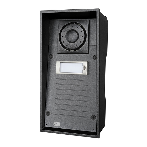
Installation manual 2N® IP Force ® IP Force is very easy to install. All you have to do is connect the system into your LAN via a network cable and feed it from a 12 V power supply or your PoE supporting LAN. - Page 5 Installation manual 2N® IP Force Basic Units One-Button • 1 button 2N Part • control of two electric locks No. 9151101W • additional switch connection option • 10 W loudspeaker, IP69K Axis Part No. 01336-001 5 / 118...
- Page 6 Installation manual 2N® IP Force One-Button • IP69K Part • 1 button No. 9151101CW • camera • 10 W loudspeaker, IP69K • extra robust version • control of two electric locks • additional switch connection option • IP69K 2N Part •...
- Page 7 Installation manual 2N® IP Force One-Button • 1 button, pictograms, 2N Part • possibility of connecting card reader No. 9151101RPW • control of two electric locks • additional switch connection option Axis Part No. • 10 W loudspeaker, IP69K 01335-001 •...
- Page 8 Installation manual 2N® IP Force One-Button • 1 button, pictograms, 2N Part • with HD camera, No. 9151101CHR • possibility of connecting card reader • control of two electric locks • additional switch connection option • 10 W loudspeaker, IP69K Axis Part No.
- Page 9 Installation manual 2N® IP Force One-Button • 10 W loudspeaker, IP69K 2N Part • 1 button No. 9151101CKW • keypad • camera • control of two electric locks • additional switch connection option • 10 W loudspeaker, IP69K 2N Part •...
- Page 10 Installation manual 2N® IP Force Two-Button • 2 buttons 2N Part • HD camera No. 9151102CHR • possibility of connecting card reader • control of two electric locks • additional switch connection option • 10 W loudspeaker, IP69K Axis Part No.
- Page 11 Installation manual 2N® IP Force Two-Button • 2 buttons 2N Part • card reader connection option No. 9151102RW • control of two electric locks • additional switch connection option Axis Part No. • 10 W loudspeaker, IP69K 01341-001 ...
- Page 12 Installation manual 2N® IP Force Four-Button • 10 W loudspeaker, IP69K 2N Part • 4 buttons No. 9151104W • control of two electric locks • additional switch connection option Axis Part No. 01342-001 • 10 W loudspeaker, IP69K 2N Part •...
- Page 13 Installation manual 2N® IP Force Four-Button • 10 W loudspeaker, IP69K 2N Part • 4 buttons No. 9151104CHW • HD camera • control of two electric locks Axis Part No. • additional switch connection option • night vision 01343-001 ®...
- Page 14 Installation manual 2N® IP Force Flush Mounting Box • frame • included with basic unit • Brick flush mounting box 2N Part • Dimension: 132 x 223 x 83 mm No. 9151001 Axis Part No. 01348-001 14 / 118...
- Page 15 Installation manual 2N® IP Force • Plasterboard flush mounting box 2N Part • Dimension: 237 x 129 x 70 mm No. 9151002 • Hole: 237 x 118 mm Axis Part No. 01349-001 Mounting Accessories • Gooseneck stand 2N Part No.
- Page 16 Installation manual 2N® IP Force • Gooseneck stand double 2N Part No. • Height: 115 cm (45”) and 203 cm (80”) 9151007 Axis Part No. 01550-001 • Installation adapter (US only) 2N Part No. 9151006 Axis Part No.
- Page 17 • Indoor Touch 2.0, an elegant internal touch panel, is suitable for all 2N IP intercoms. On the panel’s display not only Axis Part No. 01668-001 can you find out who is at the door, but you an also start conversation with the visitor, open the lock or turn on the light in ...
- Page 18 • Indoor Touch 2.0, an elegant internal touch panel, is suitable for all 2N IP intercoms. On the panel’s display not only Axis Part No. 01669-001 can you find out who is at the door, but you can also start conversation with the visitor, open the lock or turn on the light in ...
- Page 19 Installation manual 2N® IP Force ® 2N Part No. 91378382W • Indoor Touch desk stand white Axis Part No. 01426-001 VoIP Telephones • Grandstream GXV3240 VoIP video telephone 2N Part No. 91378357 • GXV3240 is the successor to the popular GXV3140 model, which allows for comfortable video calls in the IP network.
- Page 20 Installation manual 2N® IP Force Electric Locks • BEFO 11211 2N Part No. 932071E • 12 V / 230 mA DC • low consumption • BEFO 11221 with momentum pin 2N Part No. 932081E • 12 V / 230 mA DC •...
- Page 21 The failsafe lock is closed when electricity is switched on. When electricity is interrupted, the lock is opened. • It contains a built-in contact to indicate whether the door is open or closed. • FAQ: Electric locks – Difference between locks in 2N IP intercom accesories 21 / 118...
- Page 22 Installation manual 2N® IP Force Power Supply • PoE injetor – with EU cable Part Numbers: • PoE injector – with US cable • For intercom power supply via an Ethernet cable where no 2N Part No. 91378100E PoE switch is available.
- Page 23 ® 2N Part No. 9151011 • Internal RFID card reader 125 kHz for installation in 2N IP Force intercoms. Allows the use of EM4xxx cards. Another two switches, Axis Part No. 01344-001 two logical inputs and a Wiegand interface are available. It is ®...
- Page 24 IP Force mounting. Two switches, two logical inputs and Axis Part No. 01730-001 ® a Wiegand interface are available. It is compatible with the 2N IP Force two-button and pictogram models. • Includes a tamper switch to signal when the front panel is opened.
- Page 25 2N Part No. 9151021 • IP Force Induction Loop ® • An induction loop transmits sound wirelessly from the 2N Axis Part No. 02338-001 Force to the earphones of people with hearing disabilities and enables them to hear and perceive sounds better. ® ...
- Page 26 External IP Relay – 1 output 2N Part No. 9137410E • Standalone IP device which can be controlled by HTTP commands sent by 2N IP intercom, which can thus Axis Part No. 01397-001 control devices on unlimited distance. • External IP Relay – 4 outputs, PoE 2N Part No. 9137411E...
- Page 27 2N Part No. 9159050 • Induction Loop • An induction loop transmits sound wirelessly from the 2N IP Axis Part No. 01391-001 intercom to the earphones of people with hearing disabilities and enables them to hear and perceive sounds better. 27 / 118...
- Page 28 Installation manual 2N® IP Force ® 2N Part No. 9159052 • Power supply for 2N Induction Loop • External power supply for the induction loop Axis Part No. 01393-001 • Input 230 V AC • Output 12 V DC •...
- Page 29 Installation manual 2N® IP Force • Exit button 2N Part No. 9159013 • (suitable for Internal RFID card reader or Security relay) • A button for connection to a logic input for opening a door inside a building. •...
- Page 30 Installation manual 2N® IP Force • External 13.56 MHz Mifare RFID card reader, Wiegand 2N Part No. 9159031 • Secondary reader for connection to an internal reader. Provides Axis Part No. 01390-001 card entry control from both sides of the door. IP68 cover, also suitable for exteriors.
- Page 31 NFC/HCE using 2N IP intercom web interface or the ® Access Commander application. It reads the same types of cards and devices as the card readers in 2N IP intercoms. • 13.56 MHz/ISO/IEC 14443A Mifare Classic 1k & 4k, DESFire EV1, Mini, Plus S&X, Ultralight, Ultralight C...
- Page 32 Installation manual 2N® IP Force License • Enhanced Audio 2N Part No. 9137905 • Enhanced Video 2N Part No. 9137906 • Enhanced Integration 2N Part 9137907 • Enhanced Security 2N Part No. 9137908 • Gold 2N Part No. 9137909 •...
-
Page 33: Terms And Symbols
• Refer to the Configuration Manual for 2N IP intercoms, Subs. 3.2 Function Licensing for details. • For more accessories and particular advice please contact your local distributor of 2N products. • FAQ: Induction loop – How to connect it with 2N IP intercoms 1.2 Terms and Symbols... -
Page 34: Description And Installation
2.3 Electric Installation • 2.4 Extending Module Connection • 2.5 Button Tags 2.1 Before You Start Product Completeness Check ® Before you start please check the contents of your 2N IP Force delivery: ® • 1x 2N IP Force • 1x frame (of the corresponding colour) •... - Page 35 Remember that dowels of poor quality may easily get loose and fall out of the wall! ® • Stainless steel screws are used for the 2N IP Force assembly. Other screws than stainless steel ones corrode soon and may aesthetically deteriorate the surrounding environment! •...
- Page 36 Installation manual 2N® IP Force Warning Be sure keep strictly the hole dimensions while mounting the device into classic bricks without the flush mounting box as shown in the picture with dimensions. – 36 / 118...
- Page 37 Installation manual 2N® IP Force What You Need: • The brick flush mounting box, Part No. 9151001 • Hole: (132 x 223 x 83) mm 37 / 118...
- Page 38 Installation manual 2N® IP Force 38 / 118...
- Page 39 Installation manual 2N® IP Force Make a hole using the template. Suppose that all the required cables have been carried into the hole. Put the intercom inside and place the set onto the hole to make sure that the hole is deep enough and the uneven edge is perfectly covered with the frame.
- Page 40 Installation manual 2N® IP Force Caution • The hole depth depends on the insulation layer thickness. If the insulation layer is rather thick, you may need longer screws! If there are hollow bricks under the insulation, make sure that your screws pass through the whole dowel (50 mm) and fix the dowel reliably.
- Page 41 • Hole: (132 x 223 x 83) mm ® Suppose you intend to install your 2N IP Force unit into a wall made of hollow bricks. Note that the external side of the bricks gets damaged by cutting and the dowels cannot practically be fixed into the thin internal part of the bricks.
- Page 42 Installation manual 2N® IP Force Wall Mounting What You Need: ® • Just your 2N IP Force unit Wall (surface) mounting is used where flush mounting is inapplicable (in concrete and steel structures, entry barrier columns, etc.). The frame is not used.
- Page 43 Installation manual 2N® IP Force • Wall mounting may be a problem where vandals may destroy the unit (in public garages, e.g.). Therefore, use steel fixing elements instead of the dowels and screws included in the delivery. • Be sure to insert plugs into unused bushing holes to avoid water leakage during facade cleaning, for example.
- Page 44 IP Force cable fee-out! Use of Cable Bushings ® The cable bushings included in the 2N IP Force delivery are designed for the following cables: • Big bushing: for two cables of the diameter of 5–6 mm (UTP cable), or, upon insert replacement, for one thick cable/tube of the diameter of up to 14 mm. ...
- Page 45 Installation manual 2N® IP Force • Even a LAN cable including the RJ-45 connector can go through the big bushing. See below for instructions. How to Pull a RJ-45 Terminated Cable through a Bushing 1. Unscrew the big bushing nut completely.
- Page 46 Installation manual 2N® IP Force 5. Pull the cable connector though the bushing body into the intercom and clip it into the motherboard connector. 6. Move the sealing including the cover along the cable as far as the bushing body, or add a plug if necessary.
-
Page 47: Electric Installation
The device must be part of the electrical system of the building. PCB Connectors ® Picture shows the lay-out of connectors on the 2N IP Force printed circuit board (PCB). Cables, accessories and other system components are connected to connectors X1 through X22. - Page 48 Installation manual 2N® IP Force • X8 – Extending module (RFID card reader or additional switch) • X10 – Buttons 1 through 4 • X11 – LAN • X12 – Servicing connector • X13 – Keypad module • X15 – Left-hand microphone • X16 – Right-hand microphone • X17 – Relay NO and NC contact max. 30 V / 1 A AC/DC. Used for connection of non-critical devices only (lights, e.g.).
- Page 49 Installation manual 2N® IP Force ® IP Force Connectors, PCB Version 555v3 49 / 118...
- Page 50 Installation manual 2N® IP Force ® IP Force Connectors, PCB Version 555v4 50 / 118...
- Page 51 Installation manual 2N® IP Force ® IP Force Connectors, PCB Version 555v5 • Output wiring diagram for Relay terminals 51 / 118...
- Page 52 Installation manual 2N® IP Force Wiring diagram for the controlled device’s electric circuit closing Wiring diagram for the controlled device’s electric circuit opening LAN Connection ® IP Force is connected to the LAN via a RJ-45 terminated (connector X11) UTP/STP cable (of category Cat 5e or higher).
- Page 53 Installation manual 2N® IP Force • We recommend the use of a shielded SSTP Ethernet cable. External Power Supply Connection ® IP Force can be fed either from an external 12 V ±15 % / 2 A DC power supply or from the LAN equipped with the PoE 802.3af supporting network elements.
- Page 54 Installation manual 2N® IP Force Warning When you connect a device containing a coil, such as a relay or an electromagnetic lock, it is necessary to protect the intercom against voltage peak while switching off the induction load. For this way of protection we recommend a diode 1 A / 1000 V (e.g., 1N4007, 1N5407,...
- Page 55 The delay after pressing RESET till the first light and sound signalling is set to 15–35 s depending on the 2N IP intercom/answering unit model used. ® • 24 s is the valid value for 2N IP Force HW version 8. Static IP Address Setting Follow the instructions below to switch on the Static IP address mode (DHCP OFF): •...
- Page 56 Installation manual 2N® IP Force Dynamic IP Address Setting Follow the instructions below to switch on the Dynamic IP address mode (DCHP ON): • Press and hold the RESET button. • Wait until the red and green LEDs go on simultaneously on the device and the acoustic signal ...
- Page 57 Installation manual 2N® IP Force Caution • In case of resetting the factory default settings on a device with a version of firmware 2.18 or higher it is necessary to reprogram the ® Security Relay using the instructions from section 2.4.
- Page 58 Installation manual 2N® IP Force • In case of resetting the factory default settings on a device with a version of firmware 2.18 or higher it is necessary to reprogram the ® IP Security Relay using the instructions from section 2.4.
- Page 59 Water leakage may damage the electronic part of the system. ® • Stainless steel screws are used for the 2N IP Force assembly. Other screws than stainless steel ones corrode soon and may aesthetically deteriorate the surrounding environment! ...
- Page 60 Installation manual 2N® IP Force Location Name Description Basic Unit Relay 1 Passive relay switch: NO and NC contacts, up to 30 V / 1 A AC/DC. Used for connection of non-critical devices only (lights, e.g.). Output 1 Active switch output: 9 up to 13 V DC depending on...
-
Page 61: Overvoltage Protection
2N device wiring may be exposed to atmospheric effects resulting in overvoltage that may subsequently damage any devices installed outside the building, on its outer wall or roof. Overvoltage may damage devices connected to these wires and installed inside the building as well. -
Page 62: Extending Module Connection
Installation manual 2N® IP Force a) as close as possible to the device installed outside the building or on its outer wall/roof, b) as close as possible to the point where the wires leave the building. OVP = overvoltage ... - Page 63 It is recommended to use the tamper switch. ® • FAQ: Tamper switch - How to install it into the 2N IP Force Specifications version 5: • IN2 terminals for input in passive / active mode (-30 V to +30 V DC) •...
- Page 64 Installation manual 2N® IP Force • Tamper switch: 24 V / 50 mA AC/DC Module mounting: Switch off the intercom. Remove the front panel from the intercom. According to your model If you are mounting the switch into a two-nameplate model, demount the button PCB (1) and remove the right-hand bottom spacer (there are four PCB fitting spacers altogether).
- Page 65 Installation manual 2N® IP Force 65 / 118...
- Page 66 Installation manual 2N® IP Force 66 / 118...
- Page 67 Installation manual 2N® IP Force Module settings: Refer to the Configuration Manual for details. Connection: 67 / 118...
- Page 68 RFID Card Reader is installed, it is not possible to install the Additional Switch. Function: ® The 2N IP Force Internal RFID Card Reader adds two logical inputs, two ® additional switches and a tamper switch to the 2N IP Force basic unit. 68 / 118...
- Page 69 The purpose of the tamper switch is to signal any unauthorised opening of the intercom (to prevent a theft, e.g.). It is recommended to use the tamper switch. ® • FAQ: Tamper switch - How to install it into the 2N IP Force Specifications: Card reader • Compatible with: •...
- Page 70 Mounting guide:...
- Page 71 Installation manual 2N® IP Force Switch off the intercom. Remove the front panel (7) from the intercom. Mount antenna board (8). Use two enclosed self tapping screws (9). Plug enclosed cable (11) to the antenna board connector. Demount a button PCB (1). Don't disconnect its cable! There will stay four spacers after the switch board removal.
- Page 72 Installation manual 2N® IP Force 72 / 118...
- Page 73 Module setting:...
- Page 74 Installation manual 2N® IP Force Refer to the Configuration Manual for details of Wiegand, outputs and reader. Refer to the Automation manual for details of input, red LED and tamper function and use. Connection: Wiegand Input Technical Parameters Current 5 mA...
- Page 75 Internal RFID Card Reader 13.56 MHz The Internal RFID Card Reader 13.56 MHz (Part No. 9151031/9151017) is used for reading RFID card Ids in the 13.56 MHz band, NFC supported. This ® module is intended for mounting into the 2N IP Force model 9151101RPW, 9151101CRPW, 9151101CHRPW,...
- Page 76 The purpose of the tamper switch is to signal any unauthorised opening of the intercom (to prevent a theft, e.g.). It is recommended to use the tamper switch. ® • FAQ: Tamper switch – How to install it into the 2N IP Force Specifications: Card reader • Operating frequency: 13.56 MHz ®...
- Page 77 Installation manual 2N® IP Force • = approx. 8.3 V • = approx. 8.3 V • = approx. 0.5 mA LOOP Signalling output • Internal red LED under reader window PWR • For external RFID card reader • Out: 9 to 12 V / 350 mA depends on power supply WIEGAND interface •...
- Page 78 Installation manual 2N® IP Force 78 / 118...
- Page 79 Installation manual 2N® IP Force 79 / 118...
- Page 80 Module setting:...
- Page 81 The Internal RFID Card Reader 13.56 MHz (Part No. 9151031S/9151019) is used for reading RFID card Ids in the 13.56 MHz band, NFC supported. This ® module is intended for mounting into the 2N IP Force model 9151101RPW, 9151101CRPW, 9151101CHRPW, 9151102RW, 9151102CRW a 9151102CHRW. These models have an window, which is necessary for antenna operation. If the Internal RFID Card Reader is installed, it is not possible to install...
- Page 82 The purpose of the tamper switch is to signal any unauthorised opening of the intercom (to prevent a theft, e.g.). It is recommended to use the tamper switch. ® • FAQ: Tamper switch – How to install it into the 2N IP Force Specifications: Card reader • Operating frequency: 13.56 MHz ®...
- Page 83 Active output...
- Page 84 Installation manual 2N® IP Force • 9 to 12 V / 700 mA transistor switched output. Depends on power supply (PoE: 9 V or power supply voltage minus 1 V). Logical inputs Active mode – requires external voltage (JP2 jumper OFF) •...
- Page 85 Installation manual 2N® IP Force 85 / 118...
- Page 86 Installation manual 2N® IP Force 86 / 118...
- Page 87 Module setting:...
- Page 88 Installation manual 2N® IP Force Refer to the Configuration Manual for details of Wiegand, outputs and reader. Refer to the Automation manual for details of input, red LED and tamper function and use. Connection: 88 / 118...
- Page 89 Security Relay...
- Page 90 ® between the intercom and the connected electric lock. The 2N IP Security Relay is designed for any 2N IP intercom model with firmware versions 1.15 and higher. It significantly enhances security of the connected electric lock as it prevents lock opening by forced intercom tampering. ...
- Page 91 Activate the intercom switch using the keypad, telephone, etc. The first code sent from the intercom will be ® stored in the memory and considered valid. After code initialisation, the 2N Security Relay will pass into the operational mode (the green LED is blinking).
- Page 92 ® Security Relay using the instructions above. ® • FAQ: Security Relay – what it is and how to use it with 2N IP intercom? Connection: Wiegand Isolator ® The 2N Wiegand Isolator (Part No. 9159011) is usef for galvanic isolation of the Wiegand bus. ...
- Page 93 Installation manual 2N® IP Force Connection of the 2N IP intercoms Card Reader to a security system unit is a typical example of application. Function: ® The 2N Wiegand Isolator separates galvanically a two-wire Wiegand bus in one direction and a status LED signal in the other direction. The module is power supplied from the Wiegand bus receiver side.
- Page 94 Installation manual 2N® IP Force Connection: 94 / 118...
- Page 95 V power supply outlets to the B connector. Connect the special cable to the intercom and connect the power supply to the mains. You can place the mated A and B connectors into the 2N IP intercom cover. The connectors help you connect stripped cables. Open the connector by pushing a thin screwdriver onto the white spots at its front and close the connector by sliding the movable part through a side gap.
- Page 96 Installation manual 2N® IP Force Finally, test the amplifier function using a suitable receiver for hearing impaired persons or magnetic field communication tester. No other settings are required. Specifications: • Supply voltage: 8 18 V DC • Supply current at 12 V supply: •...
- Page 97 Induction Loop internal ® ® The 2N IP Force Induction Loop (Part No. 9151021) is one of the 2N IP Force extending modules, used for people with disabled hearing equipped with a special hearing aid that receives reproduced sound via a magnetic field sensor.
- Page 98 Installation manual 2N® IP Force 98 / 118...
- Page 99 Installation manual 2N® IP Force 99 / 118...
-
Page 100: Button Tags
Always use waterproof foil (enclosed or other) for the tags. Never use paper or ink jet printing to avoid damage due to water leakage! • A template for printing nametags can be downloaded from www.2n.cz. Tag Inserting/Replacing Instructions ® IP Force provides an intuitive, easy access to the name plates. -
Page 101: Function And Use
Installation manual 2N® IP Force 3. Function and Use ® In this section we describe the basic and extending functions of the 2N IP Force product. Here is what you can find in this section: • 3.1 Configuration • 3.2 Control •... - Page 102 Installation manual 2N® IP Force Note • Be sure to press the button sequence within thirty seconds after the sound signal for security reasons. Up to 2 s intervals are allowed between the presses. Static IP Address Setting for 4-button models Follow the instructions below to enable the static IP address mode: ®...
- Page 103 Installation manual 2N® IP Force Caution • The 1, 1, 1, 2, 2, 3 sequence must be entered within 30 seconds after the first sound signal for security reasons. The inter-digit delay may be 2 s at most.
-
Page 104: Control
The static IP address mode will be switched into the dynamic IP address mode and vice versa upon restart. 3.2 Control ® This subsection describes how to control 2N IP Force when viewed by an external user. Speed Dial Buttons Press the speed dial buttons on the basic unit to make quick dialling for the first 1, 2 or 4 positions (depending on the model type) in the telephone 104 / ... - Page 105 button anytime to terminate a call if enabled so in the Hang up with # parameter in the unit configuration. Calling to Telephone Number ® You can dial a telephone number using your numerical keypad from 2N IP Force if the Enable telephone function parameter is on. Procedure: Press the ...
-
Page 106: Maintenance
Installation manual 2N® IP Force Answering and Rejecting Incoming Calls ® If the automatic incoming call answering function is off, 2N IP Force signals an incoming call with loud ringing. Push the button to answer the call and the to reject the call. This function is available in models equipped with a numerical keypad only. -
Page 107: Downloads
Installation manual 2N® IP Force Warning • Avoid peroxide-based cleaners. ® • The 2N IP Force models of Part Nos. 9151101W and 9151101CW may be cleaned with WAP high pressure washers. Future Tag Replacement, Programming Changes For necessary steps refer to the preceding subsections. Keep the following for future changes: •... -
Page 108: Technical Parameters
Installation manual 2N® IP Force 4. Technical Parameters Signalling protocol • SIP (UDP, TCP, TLS) Buttons • Button design: Transparent, white backlit buttons with easily replaceable name tags • Count of buttons: 1, 2 or 4 • Numerical keypad: optional Audio •... - Page 109 Installation manual 2N® IP Force Video stream • Protocols: RTP / RTSP / HTTP • Codecs: H.263, H.263+, H.264, MPEG-4, M-JPEG • IP camera function: Yes, ONVIF v2.4 profile S compatible Bandwidth • Audio codecs • PCMA, PCMU – 64 kbps (with 85.6 kbps headers) •...
- Page 110 Installation manual 2N® IP Force • MJPEG • Low quality: QVGA (320 x 240), 10 fps, quality 70: 435 kbps with headers • Medium quality: VGA (640 x 480), 15 fps, quality 85: 506 kbps • High quality: SXGA (1280 x 960), 15 fps, quality 95: 8 Mbps ...
-
Page 111: General Drawings
Installation manual 2N® IP Force • Optional: Includes also one input, active output, relay, tamper switch • Active switch output: 9 up to 13 V DC depending on power supply (PoE: 9 V; adaptor: power supply voltage minus 1 V), max 600 mA • Passive relay switch: NO and NC contacts, up to 30 V / 1 A AC/DC Mechanical properties •... - Page 112 Installation manual 2N® IP Force Flush mounting Plasterbo Flush mounting mounting with box 112 / 118...
-
Page 113: Supplementary Information
• 5.2 Directives, Laws and Regulations • 5.3 General Instructions and Cautions 5.1 Troubleshooting For the most frequently asked questions refer to faq.2n.cz. 5.2 Directives, Laws and Regulations ® IP Force conforms to the following directives and regulations: • 2014/53/EU for radio equipment •... - Page 114 The latest versions are available at https://www.2n.cz/cs_CZ/ or can be updated via the configuration interface if the devices are adequately technically equipped. Should the customer use a product / device...
-
Page 115: General Instructions And Cautions
/ device in contradiction to the manufacturer’s instructions, guidelines or recommendations or in conjunction with unsuitable products / devices of other suppliers, the customer agrees that the 2N TELEKOMUNIKACE a.s. company shall not be held liable for any functionality limitation of such a product or any damage, loss or injury related to this potential functionality limitation. - Page 116 Installation manual 2N® IP Force The manufacturer shall not be held liable for any damage of the product arising during the shipping thereof. The manufacturer shall not make any warrant with regard to data loss or damage. The manufacturer shall not be liable and responsible for any direct or indirect damage incurred as a result of a use of the product in contradiction herewith or a failure of the product due to a use in contradiction herewith.
- Page 117 Installation manual 2N® IP Force Deliver your expired electric appliances and battery packs removed from them to dedicated dumpsites or containers or give them back to the dealer or manufacturer for environmental-friendly disposal. The dealer or manufacturer shall take the product back free of charge and without requiring another purchase.
- Page 118 Installation manual 2N® IP Force 118 / 118...
Need help?
Do you have a question about the IP Force 9151101W and is the answer not in the manual?
Questions and answers