Table of Contents
Advertisement
Quick Links
Advertisement
Table of Contents

Related Manuals for 2N Indoor View 91378601WH


Summary of Contents for 2N Indoor View 91378601WH
- Page 1 2N Indoor View User Manual...
- Page 2 Abstract Manuals for previous firmware versions can be found at https://wiki.2n.com/idview.
-
Page 3: Table Of Contents
IP address ..........................19 Web Configuration Interface Login ....................19 IP Address Retrieval ........................19 IP Address Retrieval Using 2N Network Scanner ................. 20 IP Address Retrieval using Device Display .................. 20 IP Address Retrieval Using Hardware ..................21 Firmware Update .......................... 22 Device Restart .......................... - Page 4 Icons used on the display ......................57 Home Screen ..........................59 Directory Menu .......................... 60 Call Log ............................ 62 Settings ............................. 63 Operational Statuses ........................67 Signaling of Operational Statuses ....................68 Calls ............................69 Idle Mode ..........................72 Device Lock (Screen Lock) ......................73 Do Not Disturb Mode .........................
-
Page 5: Symbols And Terms Used
Symbols and Terms Used Symbols and Terms Used The following symbols and pictograms are used in the manual: DANGER Always abide by this information to prevent persons from injury. WARNING Always abide by this information to prevent damage to the device. CAUTION Important information for system functionality. -
Page 6: Product Description
The section also includes safety precautions. Basic Features 2N Indoor View is an indoor IP/SIP unit allowing for audio and video communication with the 2N IP intercoms. The device includes a panel with a 3 mm thick hardened glass touchscreen, Speakerphone, high-quality microphone with excellent audibility and intelligibility properties, Ethernet LAN interface and induction loop, external power supply and doorbell connectors. -
Page 7: Product And Accessory Versions
Choose the proper a mounting box depending on your particular installation needs. Part No. 91378800 Axis Part No. 01700-001 Mounting box Wall/plasterboard flush mounting box for 2N indoor answering units. Not included in the package of 2N Indoor View. Part No. 91378803 Axis Part No. 02320-001 Wall mounting box Wall surface mounting box for 2N indoor answering units. -
Page 8: Device Description
Package Completeness Check (p. 8) • Component Layout (p. 9) Package Completeness Check Please check the product delivery before installation. Contents: 2N Indoor View External power and doorbell button terminals Certificate of ownership 2.5 mm hexagon key wrench Quick Start manual... -
Page 9: Component Layout
Device Description Component Layout Front Display Microphone Speaker Anchoring holes... - Page 10 Device Description Rear External induction loop output RESET Button Doorbell button input 12 V / 1 A DC power supply input Ethernet...
-
Page 11: Mechanical Installation
Mechanical Installation Mechanical Installation This subsection provides the 2N Indoor View installation and connection instructions. The device can be installed on any of the following ways: • into a wall using a mounting box (not included in the package), • onto a wall using a mounting box (not included in the package), •... -
Page 12: Flush Mounting
Flush Mounting Box Device Installation (p. 14) Flush Mounting Box Installation 2N Indoor View is designed for flush mounting (brick, plasterboard, wood). Use the flush mounting box (Part No. 91378800), which is not included in the package. Alternatively, the product can be surface installed in a wall box or mounted into a desk stand (Part No. - Page 13 When the mortar hardens, break off the clips and cap the box with the cover provided. Use anchoring elements to fix the device into plasterboard. To install 2N Indoor View into a flush mounting box, get a 2.5 mm hexagon key wrench, which is included in the package.
-
Page 14: Wall Mounting
Wall Mounting Box Installation for Device Wall Mounting 2N Indoor View can be installed using a wall mounting box. The device display slope is 12% in this type of installation. Use the mounting box (Part No. 91378803), which is not included in the package. -
Page 15: Stand Installation
25 cm will lead to the place. Download the Drilling template from 2N.com. Fit the wall mounting box into the predrilled holes. Pull the available cables through the box opening. Use a water level for a more precise levelling. -
Page 16: Power Supply
Power Supply Power supply must comply with PS1 class output. You can feed 2N Indoor View as follows: Use an Ethernet cable connected to a PoE supply or PoE supporting Ethernet switch/router. Using a 12 V / 1 A DC power adapter connected to the backside terminal board. -
Page 17: Poe Supply Connection
Make sure that the external power supply meets the power supply class PS2/LPS. PoE Supply Connection Use a standard straight RJ-45 terminated cable to connect 2N Indoor View to the Ethernet. The device supports the 10BaseT and 100BaseT protocols. CAUTION •... - Page 18 Mechanical Installation Figure 1. Ethernet cable connector Figure 2. Ethernet socket unused unused unused unused WARNING This device cannot be connected directly to telecom lines (or public wireless networks) of any telecom service providers (i.e. mobile providers, landline providers or Internet provid- ers).
-
Page 19: Brief Guidelines
Call Connection (p. 23) Device Configuration Interface Access 2N Indoor View is configured via the administration web interface. Connect the device to the LAN IP and make sure it is properly powered. You have to know the IP address for access. -
Page 20: Ip Address Retrieval Using 2N Network Scanner
Brief Guidelines IP Address Retrieval Using 2N Network Scanner The application helps you find the IP addresses of all the 2N devices in the LAN. Download 2N Network Scanner from the 2N.com website. Make sure that Microsoft .NET Framework 2.0 is installed for successful app installation. -
Page 21: Ip Address Retrieval Using Hardware
Brief Guidelines IP Address Retrieval Using Hardware Follow the instructions below to retrieve the current IP address: Press and hold the RESET button. Wait until the red and green LEDs go on simultaneously on the device and the acoustic signal can be heard (approx. -
Page 22: Firmware Update
Brief Guidelines Firmware Update We recommend that the firmware is also updated during the 2N Indoor View installation. Refer to 2N.com for the latest FW version. Refer to Maintenance (p. 51) for the firmware upgrade procedure. You can make bulk updates for multiple devices via 2N Access Commander. -
Page 23: Call Connection
• a virtual number to start a call by entering the number via your numerical keypad • basic information Once saved, the contact will be shown in the phone book on the device display. Make sure that the call transmitting service is enabled on the called 2N device to make a successful call. -
Page 24: Configuration
Configuration Configuration 2N Indoor View can be configured by software via the configuration web interface or by hardware using the RESET button. Hardware configuration is used for basic settings only. • Basic Configuration via Hardware (p. 24) • Software Configuration (p. 27) •... -
Page 25: Static Ip Address Setting
Configuration Wait until the red and green LEDs go on simultaneously on the device and the acoustic signal can be heard (approx. 15–35 s). Release the RESET button. The device announces the current IP address via the speaker automatically. NOTE The delay after pressing RESET till the first light and sound signaling is set to 15–35 s depending on the device model used. -
Page 26: Dynamic Ip Address Setting
Release the RESET button. Factory Default Reset Follow the instructions below 2N Indoor View to reset the factory default values: Press and hold the RESET button. Wait until the red and green LEDs go on simultaneously on the device and the acoustic signal can be heard (approx. -
Page 27: Software Configuration
Help or use the bubble to provide feedback. Legend The start screen is also the first menu level and quick navigation (click on a tile) to selected 2N Indoor View configuration sections. -
Page 28: Device Configuration Interface Access
Configuration Device Configuration Interface Access 2N Indoor View is configured via the administration web interface. Connect the device to the LAN IP and make sure it is properly powered. You have to know the IP address for access. Domain Name Enter the domain name as “hostname.local”. -
Page 29: State
Configuration Web Configuration Interface Login Fill in the 2N Indoor View address or domain name into the internet browser. The login screen is now displayed. Should the login screen fail to appear, you must have typed a wrong IP address, port, domain name or the administration web server has been switched off. -
Page 30: Directory
Change of the SIP Proxy registration state. Directory Directory is one of the crucial parts of the device configuration. It helps you add new devices (2N IP intercoms, answering units, etc.). Up to 200 devices can be added to the directory. - Page 31 Up to 10,000 users can be imported depending on the device type. CAUTION • Special users such as those created by My2N or 2N Access Commander are not part of the directory export. • While editing the CSV file using Microsoft Excel, remember to save the file in the CSV UTF-8 format (with separators).
- Page 32 (accordingly, the internal/external camera button is/is not displayed during calls and call previews). With some 2N terminal equipment in the LAN, the information sent by the 2N terminal equipment is preferred to this setting (i.e. this setting is not needed for contacts using 2N terminals or camera-less devices).
-
Page 33: Calling
Each time profile defines the function availability based on a week calendar. Just set From-To and/or specify the weekdays for availability. The 2N IP answering units help you create up to 20 time profiles (depending on the IP model). The selected function can be assigned any time profile created in Calls >... - Page 34 Configuration • SIP 1 / SIP 2 (p. 35) • Local Calls (p. 38) Calls General Settings Call Time Limit – set the call time limit after which the call is automatically terminated. The device beeps 10 s before the call ends to signal that the call end is approaching. Enter any DTMF character into the call (# on your IP phone, e.g.) to extend the call time.
- Page 35 SIP 1 / SIP 2 2N Indoor View allows two independent SIP accounts to be configured. Thus, the intercom can be registered under two phone numbers at the same time, with two different SIP exchanges, for example. Both the SIP accounts process incoming calls equivalently. Outgoing calls are primarily processed using account SIP1.
- Page 36 Configuration Test Call – display a dialog box enabling you to make a test call to a selected phone number, see below. Authentication Authentication ID – set the alternative user ID for device authentication. Password – set the device authentication password. If your PBX requires no authentication, the parameter will not be applied.
- Page 37 Configuration IP Address Filter Enabled – enable the blocking of SIP packet receiving from addresses other than SIP Proxy and SIP Registrar. The primary purpose of the function is to enhance communication security and eliminate unauthorized phone calls. Receive Encrypted Calls Only (SRTP) – set that SRTP encrypted calls shall only be received on this account.
- Page 38 Network Identification Device ID – set the device ID to be displayed in the LAN device list in all the 2N devices in one and the same LAN. You can direct a call to this device by setting the user phone number as “device:device_ID” in these devices.
-
Page 39: Services
HTTP Command The HTTP Command on the 2N Indoor View helps send HTTP commands by a button press. You can find the buttons on the displays of the Home screen, on the display during calls and on the display during camera preview. - Page 40 (locally on your PC). Web Server 2N Indoor View can be configured using a common browser that approaches the web server integrated in the device. The HTTPS protocol is used for the browser - device communication.
-
Page 41: Hardware
Display (p. 43) • Digital Inputs (p. 44) Audio 2N Indoor View is equipped with a speaker. Set the phone call and state signaling volume control in this configuration section. Phone Call Volume Call Volume – set the phone call volume. - Page 42 RTSP Stream Address – enter the IP camera RTSP stream address: “rtsp://camera_ip_address/parame- ter1=value¶meter2=value”, refer to the parameter table below. The parameters are specific for the selected IP camera model. If you choose another 2N IP intercom for the external camera, enter “ http:// ip_address/mjpeg_stream” or “http://ip_address/h264_stream”.
- Page 43 Configuration Parameter Description Example / Values audio audio • audio=1 (enabled) • audio=0 (disabled) frame rate fps=15 (1 to 30 fps, maximum MJPEG video codec value is 15 fps). video bitrate vbr=768 for 768 kbps vcodec video codec vcodec=h264 for codec H.264 vcodec=mjpeg for codec MJPEG vres video resolution...
-
Page 44: System
Configuration Enable Screen Lock – enable the screen lock in the Idle device mode. Enter the screen lock PIN to unlock the user interface. Screen Lock PIN – set the screen lock activation/deactivation code. Display Setting Menu – display the Setting menu. Or, configure the device via the web and remote access. Display Time in Idle Mode –... - Page 45 Maintenance (p. 51) Network 2N Indoor View is connected to the LAN and has to be assigned a valid IP address or obtain the IP address from the LAN DCHP server. The Network section helps you configure the IP address and DHCP.
- Page 46 Password – enter the access password for PEAP-MSCHAPv2 authentication. Date and Time 2N Indoor View is equipped with a real time clock without power outage backup. Select Use Time from Internet (p. 0 to synchronize the device time with the Internet time or click...
- Page 47 Interrupt action before the device is restarted. NOTE The test functions are not warranted and 2N TELEKOMUNIKACE a.s. shall not be held liable for any functionality limitations and damage incurred as a result of functionality limita- tions of the beta functions. The beta functions are provided for testing purposes exclusively.
- Page 48 Configuration Certificates Some 2N Indoor View LAN services use the secure TLS protocol for communication with the other LAN devices. This protocol prevents third parties from eavesdropping on or modifying call contents. TLS is based on one/two-sided authentication, which requires certificates and private keys.
- Page 49 Configuration Auto Provisioning My2N The My2N cloud platform is used for remote administration and configuration of the 2N IP devices and helps you remotely connect to the device web interface. My2N Enabled – enable connection to My2N. My2N Security Code Serial Number –...
- Page 50 Syslog 2N Indoor View allows you to send system messages to the Syslog server including relevant information on the device states and processes for recording and subsequent analysis and audit. It is unnecessary to configure this service for common operations.
- Page 51 Download the current firmware version for your device from 2N.com. The FW upgrade does not affect configuration. The device checks the firmware file and prevents you from uploading an incorrect or corrupt file.
- Page 52 No such delicate information as passwords, access codes or phone numbers are included. This information helps 2N TELEKOMUNIKACE a.s. improve the software quality, reliability and performance. You can participate in this voluntarily and cancel your statistic data deliveries any time.
-
Page 53: Used Ports
Configuration Used Ports Service Port Proto- Direc- On by Config- Settings tion default urable 802.1x – – In/Out × × – DHCP In/Out ✓ × – ✓ TCP/U In/Out × – Echo (device discov- 8002 In/Out ✓ × – ery)* HTTP In/Out ✓... - Page 54 Configuration Service Port Proto- Direc- On by Config- Settings tion default urable In/Out × ✓ Calling RTSP client ✓ In/Out × – ✓ 5060, TCP/U In/Out × Calling 5062 SIPS 5061 In/Out × ✓ Calling Syslog × × – ✓ My2N Knocker ×...
-
Page 55: Device Control
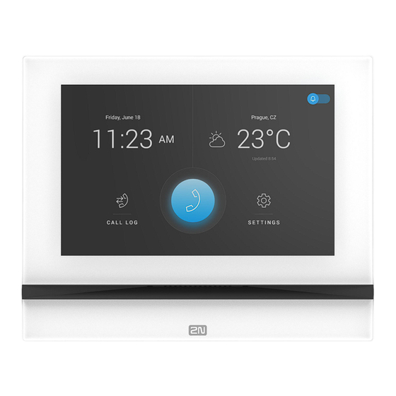
Device Control Device Control 2N Indoor View is equipped with a touch display for intuitive control. Idle mode The device will automatically go into the Idle mode if there is no activity (after selection of the 15s –10min timeout). The device configuration allows date and time, the current weather information and door contact... - Page 56 Device Control Home Screen The Home screen is set as the start screen, which is displayed when the device is switched from the Idle mode by a finger touch. It shows the current date, time, temperature and location and provides access to the Logs, Directory and Settings as well as direct activation of the Do Not Disturb mode.
-
Page 57: Icons Used On The Display
Device Control Icons used on the display Icon Description Receiving incoming call / Starting outgoing call Rejection of incoming call / Termination of outgoing/active call Remove DND mode Device configuration Call Log Incoming call ringtone volume up Incoming call ringtone volume down Incoming call ringtone volume mute Value up Value down... - Page 58 Device Control Icon Description Call info Camera Preview Camera 1 Camera 2 Camera unavailable Back Camera Video Preview Zoom In The device will automatically go into the Idle mode if there is no activity (after selection of the 15s to 10min timeout).
-
Page 59: Home Screen
Directory. If the earpiece icon is highlighted in red, 2N Indoor View cannot establish phone connections. This happens when the device has an unroutable address (0.0.0.0) or cannot log in to My2N or SIP Proxy. -
Page 60: Directory Menu
Device Control Possible actions Performance Action result Directory Menu (p. 60) is displayed with alladd- Display of Directory Menu ed devices and an external camera. Call Log (p. 62) is displayed including a list of Call Log Menu Display accomplished calls. Do Not Disturb Mode (p. - Page 61 Device Control Possible actions Perform- Action result ance Outgoing call setup An outgoing call is set up to the destination of the selected contact. Target device lock A specifically configured unlock code is sent to the target opening device and, if the code is compatible with the device, the target device lock opens.
-
Page 62: Call Log
Device Control Call Log Press to display the call log. The device displays a list of all accomplished calls including date, time, status (outgoing incoming or missed ) and information on from/to which destination the call was made. The maximum call log capacity is 20 calls. The log list and details provide door contact status in- formation as configured (door open too long, door open by force). -
Page 63: Settings
Device Control Possible Performance Action result actions Show call Call information and device camera preview if available are dis- detail played. or touch the If available, screenshots are displayed in the call detail and can be selected call switched between. The screenshot time is shown in the right-hand upper corner. - Page 64 Device Control Screen timeout – timeout after which the device automatically goes into Sleep Mode if there is no activity. Screen lock – switches the screen lock or also the so-called parental lock on/off. With the device lock on, enter the PIN code to enable the screen lock. Enter the same PIN code to disable the screen lock.
- Page 65 Device Control Reject Calls in DND Mode – with this function activated, the device rejects calls in the Do Not Disturb mode. The function can be used for immediate call forwarding at absence to a mobile phone call, for example. Mute Doorbell in DND Mode –...
- Page 66 Device Control Voicemail – enable the function that helps leave an out-of-office message to be played to the caller if the device fails to answer their incoming call for a period of time longer than as defined in Voicemail Activation Timeout.
-
Page 67: Operational Statuses
Network (p. 45). Operational Statuses This section includes a basic description of user scenarios and states that can occur during the use of 2N Indoor View, a list of user options in variable states and expected results of these actions. -
Page 68: Signaling Of Operational Statuses
Device Control • Signaling of Operational Statuses (p. 68) • Calls (p. 69) • Idle Mode (p. 72) • Device Lock (Screen Lock) (p. 73) Signaling of Operational Statuses The device generates sounds to signal changes of and switching between operational statuses. Each status change is assigned a different type of tone. -
Page 69: Calls
A short tone is played to signal that the VoIP call has been connected to the device. Calls In this state, connection or connection attempt is in progress with another device. The 2N Indoor View functions are limited, it is impossible to switch to the home page and go to menus. Possible actions are included in the table below. - Page 70 • Outgoing call initiated by the 2N Indoor View answering unit. • Incoming trying to establish connection with the 2N Indoor View answering unit. • Active call – if connection between the devices is established, sound is transmitted and camera preview if available is displayed.
- Page 71 If no unlocking code is set in the device and no default unlock code is set, the lock button is not displayed. 2N Indoor View does not transmit audio to the called Mute call device. The microphone icons turns red.
-
Page 72: Idle Mode
HTTP command HTTP com- (p. 39) sending in call. mand icon. Idle Mode 2N Indoor View transits into the Idle mode after a set inactivity period. Set the inactivity timeout Display (p. 43) > Backlight of the web config- uration. The operation power consumption is re- duced in the Idle mode. -
Page 73: Device Lock (Screen Lock)
Device Lock (Screen Lock) (p. 73)is dis- played. Device Lock (Screen Lock) When the 2N Indoor View lock is activated, enter the PIN code for device locking. The same PIN code is required for device unlocking. When the lock is activated, the device rings... -
Page 74: Do Not Disturb Mode
Device Control Do Not Disturb Mode The incoming call ringtone is switched off in the DND mode. A call can be received, rejected or ended in this mode, refer to Calls (p. 69). The display shows the camera preview if availa- ble , CLIP and the Incoming call message. -
Page 75: Maintenance - Cleaning
Maintenance - Cleaning Maintenance - Cleaning If used frequently, the device surface gets dirty. Use a piece of soft cloth moistened with clean water to clean the device. It is recommended that the principles below are followed while cleaning: • Use appropriate cleaning agents suitable for glasses, optical devices, screens, etc. •... -
Page 76: Troubleshooting
Troubleshooting Troubleshooting Refer to faq.2n.cz for the most frequently solved problems. -
Page 77: Technical Parameters
Technical Parameters Technical Parameters Supply type Consumption Polarity reversal Power Consumption protection in idle PoE, IEEE 802.3af 12 W ✓ 2.9 W 12 V DC ±10 % adapter; 1 A (rec- 12 W ✓ 2.9 W ommended) User interface Controls capacitive touch panel Display 7"... - Page 78 Technical Parameters Audio stream Prootocols RTP, RTSP Codecs G.711, G.729, G.722, L16/16kHz Video stream Protocols MJPEG, RTP, RTSP, HTTP Codecs MJPEG, H.264 Video Resolution 1280 x 720 px Frame rate up to 30 frames per s Interface 10/100BaseT, RJ-45; Cat5e or higher Doorbell input Input type Switching contact (button/relay)
- Page 79 Technical Parameters Mechanical Parameters Dimensions (w x h x 193 × 157 × 50 mm Weight 555 g Operating tempera- 0 to 50 °C ture Relative humidity 10 to 90 % non-condensing Storing temperature −20 °C to 70 °C Recommended alti- 0 to 2000 m tude...
-
Page 80: Directives, Laws And Regulations - General Instructions And Cautions
Directives, Laws and Regulations - General Instructions and Cautions Directives, Laws and Regulations - General Instructions and Cautions 2N Indoor View conforms to the following directives and regulations: • 2014/35/EU for electrical equipment designed for use within certain voltage limits • 2014/30/EU for electromagnetic compatibility •... - Page 81 / devices of other suppliers, the customer agrees that the 2N TELEKOMUNIKACE a.s. company shall not be held liable for any functionality limitation of such a product or any damage, loss or injury related to this potential functionali- ty limitation.
-
Page 82: Electric Waste And Used Battery Pack Handling
Directives, Laws and Regulations - General Instructions and Cautions All applicable legal regulations concerning the product installation and use as well as provisions of technical standards on electric installations have to be obeyed. The manufacturer shall not be liable and responsible for damage or destruction of the product or damage incurred by the consumer in case the product is used and handled contrary to the said regulations and provisions. - Page 83 2N Indoor View – User Manual © 2N Telekomunikace a. s., 2024 2N.com...
Need help?
Do you have a question about the Indoor View 91378601WH and is the answer not in the manual?
Questions and answers