Table of Contents
Advertisement
Quick Links
Advertisement
Table of Contents

Related Manuals for 2N Clip


Summary of Contents for 2N Clip
- Page 1 2N® Clip User Manual v.1.0 www.2n.com...
- Page 2 2N® Clip User Manual Obsah: • 1. Product Description • 1.1 Basic Features • 1.2 Main Units and Accessories • 1.3 Terms and Symbols Used • 1.4 Safety Precautions • 2. Device Description • 3. Mechanical Installation • 3.1 Installation Conditions •...
-
Page 3: Product Description
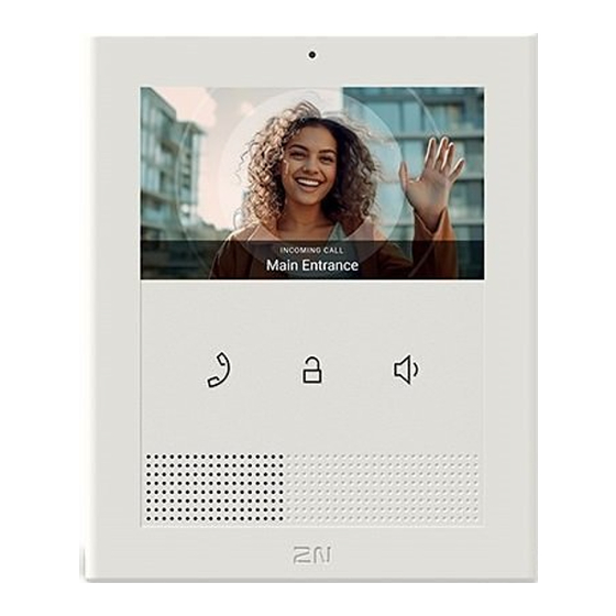
1.1 Basic Features ® Clip is an indoor IP/SIP unit providing audio/video communication with the 2N IP intercoms. The device includes a three-button control panel, Speakerphone, high-quality microphone with excellent audibility and intelligibility properties, Ethernet LAN interface and external power ®... -
Page 4: Mounting Accessories
Integrated induction loop Mounting Accessories Part No. 9138003 ® • US mounting metal holder for 2N Clip ® • Not included in the package of 2N Clip ® Part No. 9138002 • Clip stand ® • Not included in the package of 2N Clip... -
Page 5: Terms And Symbols Used
® Refer to the 2N.com company websites for the latest 2N Clip firmware and User Manual. • Where necessary, the device can be installed at a safe distance from the prohibited area and an Ethernet cable can only be carried to the required site. - Page 6 2N® Clip User Manual Caution This product and its installation and configuration techniques are not intended for persons with diminished physical, sensory or mental capacities or persons with limited experience and knowledge unless expertly supervised or duly advised as to the use of this product by a person responsible for their safety.
-
Page 7: Device Description
2N® Clip User Manual 2. Device Description This subsection provides the product package content and description of the device elements. Please check the product delivery before installation. Contents: ® Clip Certificate of ownership Quick Start manual metal holder holder fitting screws... -
Page 8: Backside Layout
2N® Clip User Manual Speaker button – Speaker Earphone button – Backside Layout RESET Button Doorbell button input LAN Ethernet/POE Status LEDs Locking latch 8 / 75... -
Page 9: Mechanical Installation
2N® Clip User Manual 3. Mechanical Installation ® This section provides instructions for a proper installation and connection of 2N Clip. The device can be installed in one of the following ways: • onto a wall using a KU68 mounting box (not included in the package), •... -
Page 10: Installation Conditions
2N® Clip User Manual 3.1 Installation Conditions ® Make sure that the following 2N Clip installation conditions are met: • There must be enough space for the device installation. • The device is designed for vertical wall mounting (perpendicular to the floor) in the height of up to 120 cm above the floor. If necessary, operate the device in a position other than as... -
Page 11: On-Wall Installation
® Having unpacked 2N Clip, remove the metal holder for installation. Use both your hands at the same time to remove it safely. A careless removal and insufficient push might lead to a locking latch damage. Hence, follow the mentioned metal holder... - Page 12 3.2.1 Flush Mounting Box Installation of Device ® Clip can be installed into a KU 68 flush mounting box using a metal holder (included in the package), the recommended height of a standard installation being 135 cm from the ground level.
- Page 13 2N® Clip User Manual Draw the pre-prepared LAN connector leading from the wall through the metal holder. Make sure that it is properly oriented for device connection after mounting. Make sure to ensure the proper orientation while installing the holder on the wall.
- Page 14 2N® Clip User Manual ® You are advised to use a metal holder (not included in the package) for 2N Clip installation in the USA. With the aid of this holder, the device can be installed into a universal US single-gang mounting box.
- Page 15 2N® Clip User Manual Slide the device gently downwards along the wall. Lock the latch to fit the device completely. Now the device is attached properly. There is a slight distance between the device and the wall due to a rather big size of the metal holder, which is fully compliant with the installation instructions.
-
Page 16: Stand Installation
® Having unpacked 2N Clip, remove the metal holder for installation. Use both your hands at the same time to remove it safely. A careless removal and insufficient push might lead to a locking latch damage. Hence, follow the mentioned metal holder... -
Page 17: Device Removal
2N® Clip User Manual Draw the pre-prepared LAN connector through the stand bottom and connect it into the LAN connector socket. Place the cable into the pre-prepared groove in the center of the stand bottom. Unstick the protective foil from the stand antislip surfaces. -
Page 18: Power Supply
Remove the device from the hooks and take it away safely. 3.5 Power Supply ® Clip is fed via an Ethernet cable connected to a PoE power supply or PoE supporting Ethernet switch/router. Supply type PoE, IEEE 802.3af ... - Page 19 2N® Clip User Manual Warning This device cannot be connected directly to telecom lines (or public wireless networks) of any telecom service providers (i.e. mobile providers, landline providers or Internet providers). A router has to be used for the device Internet connection.
-
Page 20: Ip Address Retrieval
4.1 Device Configuration Interface Access ® Clip is configured via the administration web interface. Connect the device to the LAN IP and make sure it is properly powered. You have to know the device IP address to gain access. Retrieve the IP using one of the three methods described in... -
Page 21: Installation Wizard
2N® Clip User Manual 4.2.1 IP Address Retrieval Using 2N® Network Scanner The application helps you find the IP addresses of all the 2N devices in the LAN. Download ® Network Scanner from the 2N.com website. Make sure that Microsoft .NET Framework 2.0 is installed for successful app installation. - Page 22 2N® Clip User Manual • Password: 2n 22 / 75...
- Page 23 4.2.2 IP Address Retrieval Using Device Display ® ® To retrieve the 2N Clip IP address using 2N Network Scanner, follow the instructions included IP Address Retrieval Using 2N® Network Scanner. To retrieve the IP address on the device, press any key to close the device idle mode. The Settings menu is displayed on the home screen after a long press of the buttons.
-
Page 24: Firmware Update
4.4 Factory Default Reset ® Follow the instructions below to reset the 2N Clip factory default values: Press and hold the RESET button. Wait until the red and green LEDs go on simultaneously on the device and the acoustic signal can be heard (approx. - Page 25 2N® Clip User Manual Press the button shortly (< 1 s) to restart the system without changing configuration. 25 / 75...
- Page 26 2N® Clip User Manual 5. Configuration ® Clip can be configured by software via the configuration web interface or by hardware using the RESET button. Hardware configuration is used for basic settings only. Here is what you can find in this section: •...
- Page 27 2N® Clip User Manual 5.1.2 IP Address Retrieval Follow the instructions below to retrieve the current IP address: Press and hold the RESET button. Wait until the red and green LEDs go on simultaneously on the device and the acoustic signal can be heard (approx.
- Page 28 2N® Clip User Manual Note The following network parameters will be set after restart: • IP address: 192.168.1.100 • Network mask: 255.255.255.0 • Default gateway: 192.168.1.1 5.1.4 Dynamic IP Address Setting Follow the instructions below to switch on the Static IP address mode (DCHP ON): Press and hold the RESET button.
- Page 29 2N® Clip User Manual 5.1.5 Factory Default Reset ® Follow the instructions below to reset the 2N Clip factory default values: Press and hold the RESET button. Wait until the red and green LEDs go on simultaneously on the device and the acoustic signal can be heard (approx.
-
Page 30: Software Configuration
Use the menu in the right-hand upper corner of the web interface to select language. Click the Log out button in the right-hand upper corner to log out. 5.2.2 Legend ® The start screen is also the first menu level and quick navigation (click on a tile) to selected 2N Clip configuration sections. 30 / 75... - Page 31 5.2.3 Configuration Interface Access ® Clip is configured via the administration web interface. Connect the device to the LAN IP and make sure it is properly powered. You have to know the device IP address to gain access. Retrieve the IP address using one of the three methods described in...
-
Page 32: Device Info
2N® Clip User Manual • 5.2.4.2 Services • 5.2.4.3 Call Log • 5.2.4.4 Events 5.2.4.1 Device The Device tab displays information on the model, its features, firmware and bootloader versions, etc. Device Info Factory Certificate Installed – specify the user certificate and private key to validate the intercom right to communicate with the ACS. - Page 33 RegistrationStateChanged Change of the SIP Proxy registration state. 5.2.5 Directory Directory is one of the crucial parts of the device configuration. It helps you add new devices (2N IP intercoms, answering units, etc.). Up to 200 devices can be added to the directory.
-
Page 34: Basic Settings
Call Type – set the scheme in the called destination URI. If you choose Without scheme, the URI is completed with the data from the SIP account settings. Further settings include direct SIP calls (sip:), 2N local calls (device:), Crestron calls (rava:) or calls with video management systems, e.g. AXIS Camera Station (vms:). -
Page 35: Alarm Call
Device Identity Display Name – set the name to be displayed as CLIP on the called party’s phone. Phone Number (ID) – set the device phone number (or another unique ID composed of characters and digits). -
Page 36: Sip Registrar
2N® Clip User Manual Test Call – display a dialog box enabling you to make a test call to a selected phone number, see below. Authentication Use Authentication ID – select the use of an alternative ID for device authentication. - Page 37 2N® Clip User Manual PRACK Allowed – enable the PRACK method (reliable confirmation of SIP messages with codes 101–199). REFER Allowed – enable the REFER method for call redirection. Send Keep Alive Packets – define whether or not the device shall periodically inquire about the called station status via SIP OPTIONS requests during calls (used for detection of the station failure during calls).
-
Page 38: Incoming Calls
2N® Clip User Manual Calls General Settings Call Time Limit – set the call time limit after which the call is automatically terminated. The device beeps 10 s before the call ends to signal that the call end is approaching. If the call duration is set to 0 and SRTP is not used, the call is not time limited. -
Page 39: Local Calls
Network Identification Device ID – set the device ID to be displayed in the LAN device list in all the 2N devices in one and the same LAN. You can direct a call to this device by setting the user phone number as device:device_ID in these devices. - Page 40 2N® Clip User Manual Connection to Intercoms Access Key 1, 2 – set the access key shared by the 2N answering units and intercoms. If the keys in the 2N answering units and the intercoms fail to match, the devices cannot communicate, i.e.
- Page 41 2N® Clip User Manual 5.2.6.4 Web Server ® Clip can be configured using a common browser that approaches the web server integrated in the device. The HTTPS protocol is used for the browser - device communication. Basic Settings Device Name – set the device name to be displayed in the right-hand upper corner of the web ®...
- Page 42 2N® Clip User Manual 5.2.7.1 Audio ® Clip is equipped with a speaker. Set the phone call and state signaling volume control in this configuration section. Master Volume (button-controlled) controls the master volume of the device and affects the volume of both the calls and signaling tones. Consider the noise level of the ambient environment while setting this parameter.
-
Page 43: Digital Inputs
2N® Clip User Manual Backlight Display Backlight Intensity – set the backlight brightness level. The value is given as a percentage of the maximum possible LED brightness. Switch into Idle Mode in – set the timeout after which the devices goes into the Idle mode due to inactivity. -
Page 44: Network Identification
2N® Clip User Manual 5.2.8.1 Network ® Clip is connected to the LAN and has to be assigned a valid IP address or obtain the IP address from the LAN DCHP server. The Network section helps you configure the IP address and DHCP. -
Page 45: Lan Port Settings
2N® Clip User Manual packets with the set ID. An incorrect setting may result in a connection loss and subsequent factory reset. LAN Port Settings Required Port Mode – set the LAN port mode to be preferred (Automatic or Half Duplex – 10 Mbps). -
Page 46: Current Time
5.2.8.2 Date and Time ® Clip is equipped with a real time clock without power outage backup. Select Use Time from Internet to synchronize the device time with the Internet time or click Synchronize with Browser to synchronize time with your current PC time. - Page 47 ® Some 2N Clip LAN services use the secure TLS protocol for communication with the other LAN devices. This protocol prevents third parties from eavesdropping on or modifying call contents. TLS is based on one/two-sided authentication, which requires certificates and private keys.
-
Page 48: Auto Provisioning
NIST P-256) and secp384r1 (aka NIST P-384) curves only. 5.2.8.5 Auto Provisioning My2N The My2N cloud platform is used for remote administration and configuration of the 2N IP devices and helps you remotely connect to the device web interface. My2N Enabled – enable connection to My2N. -
Page 49: General Settings
5.2.8.6 Diagnostics ® The device 2N Clip allow you to send system messages to the Syslog server including relevant information on the device states and processes for recording, analysis and audit. It is unnecessary to configure this service for common operations. -
Page 50: Remote Packet Capture
2N® Clip User Manual Local Packet Capture We recommend that you lower the video stream transmission rate below 512 kbps while capturing packets locally. When the local capture buffer is full, the oldest packets are rewritten automatically. Click the icon to start packet capturing. -
Page 51: Usage Statistics
The whole upgrading process takes less than one minute. Download the current firmware version for your device from 2N.com. FW upgrade does not affect configuration The device checks the firmware file and prevents you from uploading an incorrect or corrupt file. - Page 52 2N® Clip User Manual Service Port Protocol Direction On by Configurab Settings default ✓ DHCP In/Out × – ✓ TCP/ In/Out × – ✓ Echo (device 8002 In/Out × – discovery)* ✓ ✓ HTTP In/Out 5.2.6.4 Web Server ✓ ✓...
- Page 53 2N® Clip User Manual Service Port Protocol Direction On by Configurab Settings default ✓ SIPS 5061 In/Out × 5.2.6.1 Phone Syslog × × – ✓ My2N Knocker × – ✓ My2N Tribble 10080 × – Tunnel ✓ Unitchannel 8011 In/Out ×...
-
Page 54: Device Control
2N® Clip User Manual 6. Device Control ® There are 3 buttons on the device front side for basic control of 2N Clip: • the earphone button is primarily used for starting an outgoing and receiving/rejecting an incoming call, •... - Page 55 2N® Clip User Manual Button Press type Generated action Short press Increases volume by one level (after the upper limit is reached, it goes to the lowest value – value rotation) Upon a volume level change, the device plays the new volume level sound. The sound signaling is shown as a percentage on the display.
-
Page 56: Home Screen
Simultaneous long press of Settings Menu displayed on the device. both buttons 6.2.1 Directory Menu ® If 2 or more devices are added to 2N Clip, the Directory menu is displayed as introduction instead of the home screen. 56 / 75... - Page 57 2N® Clip User Manual The Directory menu allows 2 devices to be displayed: device A and device B. See the note below for how to set the devices displayed. If there are more than 2 devices in the Directory, or more than 2 are selected for display, they are arranged in the order and then alphabetically.
- Page 58 2N® Clip User Manual Possible actions Performance Action result Device A unlocking Device A lock is unlocked. Short press Device B unlocking Device B lock is unlocked. Long press Display of Settings menu Simultaneous long press of Settings Menu displayed on the device.
- Page 59 2N® Clip User Manual Note Use the 5.2.7.2 Display menu in the web configuration to block the access to the menu. At that moment, the device can be only be configured by software or remote access. Possible actions Performance...
- Page 60 2N® Clip User Manual 6.2.3 Ringtone Setting Menu A long button press displays the ringtone list. A simultaneous press of the buttons for 3 seconds puts the device in the Ringtone Setting menu. Possible actions Performance Action result Cancel selection and return...
-
Page 61: Operational Statuses
This section includes a basic description of user scenarios and states that can occur during the ® use of 2N Clip, a list of user options in variable states and expected results of these actions. 6.3.1 Signaling of Operational Statuses The device generates sounds to signal changes of and switching between operational statuses. - Page 62 6.3.2 Calls ® In this state, connection or connection attempt is in progress with another device. The 2N Clip functions are limited, it is impossible to switch to the home page and go to menus. See the table below for possible actions.
- Page 63 2N® Clip User Manual Active call if the connection is established, sound is transmitted. Possible actions Performance Action result Incoming call receiving Active call, connection with the other device established. The call cannot be terminated until picked End of call Outgoing call cancelled.
- Page 64 – value rotation) 6.3.3 At Relax ® Clip transits into the Idle mode after a set inactivity period. Set the inactivity timeout in the 5.2.7.2 Display menu of the web configuration. The operation power consumption is reduced in the Idle mode.
- Page 65 6.3.4 Device Lock When the lock is activated, the device rings to signal an incoming call and displays the CLIP. The call cannot be received until the device lock is deactivated. When the lock is activated, the device rings to signal an incoming call and displays the CLIP including the camera preview if available.
- Page 66 2N® Clip User Manual Possible actions Performance Action result Device lock deactivation The device is unlocked and you can Press the buttons go to other operational statuses and perform other actions. for 3 seconds at the same time 66 / 75...
-
Page 67: Maintenance & Cleaning
2N® Clip User Manual 7. Maintenance - Cleaning If used frequently, the device surface gets dirty. Use a piece of soft cloth moistened with clean water to clean the device. You are recommended to follow the principles below while cleaning: Use appropriate cleaning agents suitable for glasses, optical devices, screens, etc. -
Page 68: Technical Parameters
2N® Clip User Manual 8. Technical Parameters Power Supply and Input Supply type PoE, IEEE 802.3af, Class 0 (0,44–12,95 W) Power Consumption Stand-by mode with screen off 1.2 W Stand-by mode with screen on 2.0 W Calling without sound 2.4 W Calling with sound 4.4 W... - Page 69 2N® Clip User Manual Codecs PCMU, PCMA, L16/16kHz, G.729, G.722 Video stream Protocols RTP, RTSP, HTTP Codecs H.264 Video Resolution 480 x 272 px Video Framerate up to 15 frames per s Interface 10/100BaseT, RJ-45; Cat5e or higher Doorbell Input Input type...
-
Page 70: Supplementary Information
9.2 Directives, Laws and Regulations - General Instructions and Cautions ® Clip conforms to the following directives and regulations: • 2014/35/EU for electrical equipment designed for use within certain voltage limits • 2014/30/EU for electromagnetic compatibility •... - Page 71 2N® Clip User Manual Changes or modifications to this unit not expressly approved by the party responsible for compliance could void the user's authority to operate this equipment. 71 / 75...
- Page 72 / device in contradiction to the manufacturer’s instructions, guidelines or recommendations or in conjunction with unsuitable products / devices of other suppliers, the customer agrees that the 2N TELEKOMUNIKACE a.s. company shall not be held liable for any functionality limitation of such a product or any damage, loss or injury related to this potential functionality limitation.
- Page 73 2N® Clip User Manual Please read this User Manual carefully before using the product. Follow all instructions and recommendations included herein. Any use of the product that is in contradiction with the instructions provided herein may result in malfunction, damage or destruction of the product.
- Page 74 2N® Clip User Manual Electric Waste and Used Battery Pack Handling Do not place used electric devices and battery packs into municipal waste containers. An undue disposal thereof might impair the environment! Deliver your expired electric appliances and battery packs removed from them to dedicated dumpsites or containers or give them back to the dealer or manufacturer for environmental- friendly disposal.
- Page 75 2N® Clip User Manual 75 / 75...
Need help?
Do you have a question about the Clip and is the answer not in the manual?
Questions and answers