Table of Contents
Advertisement
Quick Links
Advertisement
Table of Contents

Related Manuals for 2N IP Style 9157101


Summary of Contents for 2N IP Style 9157101
- Page 1 Installation Manual 2N® IP Style v.1.1 www.2n.com...
-
Page 2: Table Of Contents
2.4 Extending Module Connection • 3. Function and Use • 3.1 Configuration • 3.1.1 2N® IP Style LAN Location via 2N® Network Scanner • 3.2 2N® IP Style User Control • 3.3 Intercom Control as Viewed by Internal User •... -
Page 3: Product Overview
ARTPEC-7 – high performance microcontroller supplied by Axis. Wide-angle HD camera – allows the called user to see the calling persons on the 2N answering units, videophone displays or PC screens. The intercom is equipped with night vision, which automatically selects the night/day mode according to light. - Page 4 Installation Manual 2N® IP Style Advantages of Use: • Elegant design • 10" touch display • Weather resistance • Surface/flush mounting • Sensitive microphone and Speakerphone • Bidirectional communication – acoustic echo cancellation • Integrated color HD camera with a wide-angle lens and night vision •...
-
Page 5: Components And Associated Products
Installation Manual 2N® IP Style 1.1 Components and Associated Products Main Units ® IP Style 2N Part No. 9157101 • Main Unit • Internal 125 kHz and 13.56 MHz card reader Axis Part No. 02521-001 ® IP Style Part No. 9157101-S •... - Page 6 Installation Manual 2N® IP Style Mounting Accessories ® • IP Style surface mounting chassis Part No. 9157002 Axis Part No. 02406-001 ® • IP Style flush mounting box Part No. 9157001 Axis Part No. 02405-001 6 / 88...
- Page 7 Installation Manual 2N® IP Style Extending Modules Part No. 9155037 ® • IP Verso – Wiegand • The module helps you interconnect your system with other Axis Part No. systems via the Wiegand interface. The module is installed under 01259-001 another module, i.e.
- Page 8 Installation Manual 2N® IP Style Extending Modules • 1 m interconnecting cable • Only one interconnecting cable is allowed in a single installation. Part No. 9155050 • The maximum bus length is 7 m. • 3 m interconnecting cable •...
- Page 9 2N Indoor Units and Accessories ® • Indoor View – black • Indoor answering audio/video unit with a Part No. 91378601 touchscreen designed for all 2N IP intercoms ® • Indoor View – white • Indoor answering audio/video unit with a Part No. 91378601WH touchscreen designed for all 2N IP intercoms ...
- Page 10 Installation Manual 2N® IP Style ® • Indoor Compact – black • Indoor answering audio/video unit with a Part No. 91378501 touchscreen designed for all 2N IP intercoms ® • Indoor Compact – white • Indoor answering audio/video unit with a Part No.
- Page 11 Installation Manual 2N® IP Style ® • Indoor Talk – black • Indoor answering audio unit with a touchscreen Part No. 91378401 designed for all 2N IP intercoms ® • Indoor Talk – white • Indoor answering audio unit with a touchscreen Part No.
- Page 12 Installation Manual 2N® IP Style • Wall/plasterboard flush mounting box for 2N indoor answering units. Part No. 91378800 • Wall surface mounting box for 2N answering units. Part No. 91378803 12 / 88...
- Page 13 ® • Indoor Touch 2.0, an elegant indoor touch 91378375 panel, is designed for all 2N IP intercoms. The 91378376 display panel shows you the person standing at your door and helps you make conversation with the visitor, open the door lock or switch on the entrance hall lights.
- Page 14 ® • Indoor Touch 2.0, an elegant indoor touch 91378375WH panel, is designed for all of the 2N IP intercoms. The 91378376WH display panel shows you the person standing at your door and helps you make conversation with the visitor, open the door lock or switch on the entrance hall lights.
- Page 15 Part Number: 91378382W Part Nos.: • The exclusive type of power adapter SYS1561-0912 ® to be used with all 2N Indoor Touch 2.0 devices. 91378381E • Stabilised 12 V / 0,75 A source to be used where PoE 91378381GB supply is unavailable.
- Page 16 Installation Manual 2N® IP Style ® • IP Handset • answering unit 2N Part No. Axis Part No. • black color 1120101B 02519-001 IP Phones • Yealink SIP T58A IP video phone • simple operation 2N Part No. 91378360 •...
- Page 17 Installation Manual 2N® IP Style • Grandstream GXV3370 IP video phone 2N Part Axis Part • Android 7.0 OS No. No. • 7” touch display control 91378362EU 221014 • HD quality video calls • WiFi and Bluetooth support • Easy integration with IP intercoms, PBXs and security cameras.
- Page 18 Installation Manual 2N® IP Style • BEFO 11211MB with mechanical blocking • 12 V / 230 mA DC Part.No. 932091E • low consumption • You can set the lever mechanically into the OPEN or CLOSED position. When OPEN, the lock is constantly open, when CLOSED, it is a standard lock.
- Page 19 The reversible lock is closed when electricity is switched on. When electricity is interrupted, the lock is opened. • It contains a built-in contact to indicate whether the door is open/closed. FAQ: Electric locks - Differences between locks for 2N IP intercoms 19 / 88...
- Page 20 Installation Manual 2N® IP Style Power Supply • PoE+ injector • For intercom supply via the Ethernet cable where the Part No. 91378101 PoE+ switch is absent. • 12 V transformer • For 230 V mains voltage. Part No. 932928 •...
- Page 21 Installation Manual 2N® IP Style Two-Wire Connection ® • 2Wire • (set of 2 adapters plus EU/US/UK power supply) Part No. 9159014EU/US/UK ® • The 2N 2Wire converter allows you to use the existing two-wire cabling from your original door bell or door intercom and connect any IP device to it.
- Page 22 13.56 MHz, 125 kHz cards and Android platform devices supporting NFC/HCE using the 2N IP ® intercom web interface or 2N Access Commander. The same card/device types are read as in the 2N IP intercom card readers: • 125 kHz •...
- Page 23 External secured RFID card reader connectable to a PC via a USB interface. Suitable for system administration and adding of 13.56 MHz, 125 kHz cards and Android platform devices supporting NFC/HCE using 2N IP ® intercom web interface or the 2N Access Commander application.
- Page 24 Installation Manual 2N® IP Style Mifare Classic 1k RFID fob, 13.56 MHz Part No. 9134174 125 kHz RFID External 125 MHz RFID card reader, Wiegand Part No. 9159030 Secondary reader for connection to an internal reader. It provides card access control from both sides of the door.
- Page 25 Part No. 9134166E Biometry ® IP intercom- external fingerprint reader (USB interface) Part No. • Used for scanning user fingerprints into the device system in case an 9137423E ® extending fingerprint reader module is connected to 2N IP Style. 25 / 88...
- Page 26 Installation Manual 2N® IP Style External Switches ® Security Relay Part No. 9159010 A handy add-on that significantly enhances security Prevents lock tampering. Installed between the intercom, from which it is also supplied, and the lock to be controlled. External IP relay – 1 output Part No.
- Page 27 Installation Manual 2N® IP Style AXIS A9188 Network I/O relay module Part No. 9160501 Lift control relay module for up to 8 floors Sensors and Switches Departure button Part No. 9159013 Connects the logic input for door unlocking from inside the building.
- Page 28 ® Part No. 9159011 The 2N Wiegand isolator is designed for galvanic isolation of two separately supplied devices ® interconnected via a Wiegand bus. The 2N Wiegand isolator protects the interconnected devices against communication errors and/or damage. License Enhanced Audio Part No.
- Page 29 Enhanced Security Part No. 9137908 Gold Part No. 9137909 InformaCast Part No. 9137910 Part No. 9137915 Lift Module Part No. 9137916 • Refer to the Configuration Manual for 2N IP Intercoms, Subs. 3.2 Function Licensing for details. 29 / 88...
-
Page 30: Terms And Symbols
Installation Manual 2N® IP Style • Please refer to the local 2N distributor for more accessories and recommendations. 1.2 Terms and Symbols The following symbols and pictograms are used in the manual: Safety • Always abide by this information to prevent persons from injury. -
Page 31: Description And Installation
2.3 Electric Installation • 2.4 Extending Module Connection 2.1 Before You Start Product Completeness Check ® Before you start the installation, check whether the contents of your 2N IP Style package complies with the following list: ® • 1x 2N IP Style •... - Page 32 Installation Manual 2N® IP Style ® IP Style Main Unit Installation 32 / 88...
- Page 33 Installation Manual 2N® IP Style It is assumed that the chassis (2.2.1 Chassis Installation) or the flush mounting box (2.2.2 Mounting Box Installation) and all of the required cables have been installed. The recommended length of the accessible cables is 35 cm.
- Page 34 Installation Manual 2N® IP Style Caution • Before starting the mechanical installation on a selected place, make sure carefully that the preparations associated with it (drilling, wall cutting) cannot damage the electrical, gas, water and other existing wires and pipes.
- Page 35 Installation Manual 2N® IP Style Warning ® • We do not recommend that 2N IP Style be installed on sites exposed to long-time direct sunlight to avoid overheating. • Once overheated, the device is switched off and will be switched on automatically after it gets colder.
- Page 36 Installation Manual 2N® IP Style 2.2.1 Chassis Installation Drill chassis anchoring holes on a proper place. Use the chassis itself as a template to maintain the horizontal level and carry the cabling at the bottom edge of the cable hole. The recommended length of the accessible cables is 35 cm (1). ...
-
Page 37: Mounting Box Installation
Installation Manual 2N® IP Style 2.2.2 Mounting Box Installation Mounting Box Installation 37 / 88... - Page 38 Installation Manual 2N® IP Style Make a hole of the size of 352 (h) x 167 (w) x 45 (d) mm for the mounting box installation. It is supposed that all the required cables have been carried into the hole. The recommended length of the accessible cables is 35 cm.
-
Page 39: Electric Installation
Installation Manual 2N® IP Style Use a levelling key to check the proper height of detent embedding to make sure that the key is aligned with the mounting box edge and also touches the detent surface (6). Put the brackets to the left and right sides of the bottom detent handle (7A) and fit their positions using screws (7B). - Page 40 Caution ® • The PoE power supply cannot provide 2N IP Style with a full functionality as it only offers a limited mode (Low Power Mode) for basic configuration. This way of feeding is not recommended. Connect the device to a PoE+ supply or a convenient DC supply and restart the device.
- Page 41 Installation Manual 2N® IP Style Display backlight intensity (100%) 5.65 Audio (100 %) 1420 10.98 12.92 Video motion detection 0.24 0.28 OUTPUT 8.47 RFID ON 0.54 0.64 Pictogram backlight (100 %) 0.24 0.28 Video streaming (ON) 0.35 CPU (100 %) 0.71...
- Page 42 Installation Manual 2N® IP Style • Remove the protective connector cover to facilitate the threading of the UTP/STP cable RJ terminal into the device box. Main Unit Connectors Legend to the figure CONTROL Factory reset button POWERLED Device status LED...
- Page 43 Installation Manual 2N® IP Style TAMPER Security system connecting terminals (on the back side above the connectors) SWITCH 12 V / 0.6 A DC active output RELAY 30 V / 1 A AC/DC NO/NC contact terminals POWER 12 External 12 V / 4 A DC power supply terminals V / 4 A Optionally PoE+ 802.3at for device LAN connection...
- Page 44 Installation Manual 2N® IP Style Available Switches Location Name Description Basic Unit RELAY Passive switch: make and break contact, up to 30 V / 1 A AC/DC Used for connection of non-critical devices only (lights, e.g.). Active switch output: 8 to 12 V DC according to power supply (PoE: 10 V;...
- Page 45 Installation Manual 2N® IP Style • Relay output wiring diagram Wiring diagram for making of the electric circuit of the device to be controlled Wiring diagram for breaking of the electric circuit of the device to be controlled...
- Page 46 Wiring Diagram of IN1 connector in passive mode Security • The 12V output is used for lock connection. If, however, the unit (2N IP Intercom, 2N Access Unit) is installed where unauthorized tampering may happen (building ® envelopes), we strongly recommend that 2N Security Relay (Part No.
- Page 47 Installation Manual 2N® IP Style Warning If a coil containing device is connected, e.g. a relay / electromagnetic lock, it is necessary to protect the intercom output against voltage peak while switching off the induction load. For this way of protection, we recommend a 1 A / 1000 V diode (e.g., 1N4007, 1N5407, 1N5408) connected antiparallel to the device.
-
Page 48: Overvoltage Protection
2N device wiring may be exposed to atmospheric effects resulting in overvoltage that may subsequently damage any devices installed outside the building, on its outer wall or roof. -
Page 49: Extending Module Connection
2.4 Extending Module Connection ® ® The 2N IP Style functions can be extended by connecting any of the available 2N IP Verso extending modules via the VBUS connector. Choose the proper accessories for each type of extending module installation. •... - Page 50 Installation Manual 2N® IP Style • Secured 13.56 MHz NFC RFID card reader • 125 kHz, 13.56 MHz, NFC Bluetooth & RFID reader • 125 kHz, secured 13.56 MHz, NFC Bluetooth & RFID reader • Bluetooth reader • Induction loop •...
- Page 51 Refer towww.2n.com for the printing template. 125 kHz RFID Card Reader Module ® The 125 kHz RFID card reader (Part No. 9155032) is one of the 2N IP Verso system elements and is used for reading RFID card IDs in the 125 kHz band.
- Page 52 Installation Manual 2N® IP Style • If this module is the last one on the bus, one of the connectors remains unconnected. • The module package includes a 220 mm long interconnecting cable. The following RFID cards can be read: •...
- Page 53 Installation Manual 2N® IP Style 13.56 MHz RFID Card Reader Module ® The 13.56 MHz RFID card reader (Part No. 9155040) is one of the 2N IP Verso system elements and is used for reading RFID card IDs in the 13.56 MHz band.
- Page 54 Installation Manual 2N® IP Style • These two connectors are fully interchangeable and can be used either as inputs from the basic unit or outputs to other modules. • If this module is the last one on the bus, one of the connectors remains unconnected.
- Page 55 A combined Bluetooth and 125 kHz and secured 13.56 MHz card reader module (Part No. ® ® 9155084) is one of the 2N IP Verso system elements and is used for smartphone/2N Mobile Key tablet/card access control, making user calls and/or other functions. ®...
- Page 56 IP Verso system elements and helps authenticate users and subsequently open doors using Android and iOS based smartphones via ® the Bluetooth protocol 4.0, thus replacing the RFID cards. Make sure that 2N Mobile Key is installed available from Google Play Appstore to make authentication work properly.
- Page 57 Bluetooth modules may result in a undesired behavior. Induction Loop Module ® The Induction loop module (Part No. 9155041) is one of the 2N IP Verso system elements and is used form transmitting audio signals directly into a hearing aid via a magnetic field.
- Page 58 (skin elasticity drops with age and a higher scanning pressure may lead to fingerprint blurring). I/O Module ® The I/O module (Part No. 9155034) is one of the 2N IP Verso system elements and is used for extending the number of inputs and outputs. ®...
- Page 59 Installation Manual 2N® IP Style RELAY1 RELAY1 terminals with accessible 30 V / 1 A AC/DC NO/NC contact RELAY2 RELAY2 terminals with accessible 30 V / 1 A AC/DC NO/NC contact IN1 terminals for input in passive / active mode (−30 V to +30 V ...
- Page 60 Installation Manual 2N® IP Style Wiegand Module ® The Wiegand module (Part No. 9155037) is one of the 2N IP Verso system elements and is used for connecting an external Wiegand device (RFID card reader, fingerprint / biometric data scanner) and/or connecting the intercom to an external security exchange. All the inputs and outputs are galvanically isolated from the intercom with the insulation strength of 500 V DC.
- Page 61 Installation Manual 2N® IP Style Reader Isolated 2-wire WIEGAND IN Isolated open LED OUT switched against (up to 24 V / 50 mA) Control Panel +U input (5 to 15 V DC) for WIEGAND OUT power supply Isolated 2-wire WIEGAND OUT...
- Page 62 Recommended reader wiring diagram with OC output OSDP Module ® The OSDP module (Part No. 91550371) is one of the 2N IP Verso modules and provides ® communication between a connected device (control panel, door controller) and 2N IP Verso via the OSDP.
- Page 63 Installation Manual 2N® IP Style ® ID or PIN code. All the inputs and outputs are galvanically isolated from the 2N IP Verso system with insulation strength of 500 V DC. • The module contains two VBUS connectors for device bus connection.
- Page 64 The installation mode is signaled by a LED fast blinking on the OSDP module. Tamper Switch Module ® The Tamper switch module (Part No. 9155038) is one of the 2N IP Verso system elements and helps secure the system against tampering. ...
- Page 65 Security Relay(Part No. 9159010) is used for enhancing security between the intercom and ® the connected electric lock. 2N Security Relay is designed for any 2N IP intercom with firmware 1.15 and higher. It significantly enhances security of the connected electric lock as it prevents lock opening by forced intercom tampering.
- Page 66 Configuration: ® Connect 2N Security Relay to the properly set Security intercom output. Refer to the Configuration Manual for 2N IP Intercoms for details. Make sure that one LED at least is on or flashing. ® Press and hold the 2N Security Relay Reset button for 5 seconds to put the device in the programming mode (both the red and green LEDs are flashing).
- Page 67 Activate the switch output using the keypad, phone, etc. The first code sent from the intercom ® will be stored in the memory and considered valid. After code initialization, 2N Security Relay will pass into the operational mode (the green LED is flashing).
-
Page 68: Function And Use
Installation Manual 2N® IP Style 3. Function and Use ® This section describes the basic and extending functions of the 2N IP Style product. Here is what you can find in this section: • 3.1 Configuration • 3.2 2N® IP Style User Control •... - Page 69 Installation Manual 2N® IP Style If the address is 0.0.0.0, then the device did not get the IP address from the DHCP server and the static IP address (DHCP OFF) has to be used. If DHCP OFF is set, the device static address is 192.168.1.100.
- Page 70 Installation Manual 2N® IP Style Caution • If 2N® IP Style is supplied from an external power source using terminals, the factory reset is performed only if the device is disconnected from the LAN too. 70 / 88...
-
Page 71: Ip Style Lan Location Via 2N® Network Scanner
® Network Scanner Description The application helps find the IP addresses of the 2N devices in the LAN. Download the app from the 2N web sites (www.2n.com). Make sure that Microsoft .NET Framework 2.0 is installed for successful app installation. - Page 72 Installation Manual 2N® IP Style Once started, the application begins to automatically search for all the 2N devices in the LAN including their smart extensions which are DHCP/statically assigned IP addresses. All the devices are then displayed in a table ®...
-
Page 73: Ip Style User Control
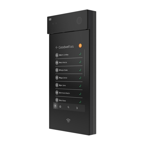
Installation Manual 2N® IP Style ® Network Scanner IP Address Change 3.2 2N® IP Style User Control Sleep Mode ® IP Style switches to the Sleep mode after an idle timeout (default value is 60 s). In the Sleep mode, you can go to the Showcase mode to display a presentation or the company logo/address (see Subs. - Page 74 Calling to Phone Book Position ® ® IP Style displays the group / user name list. The 2N IP Style Phone Book can contain up to 10 000 pre-programmed positions. The group / user list can be displayed as a classic name list or as a set of cards (refer to Subs.
- Page 75 Virtual Number Call If the Phone function enabled (refer to Subs. 5.4.1 Phone of the Configuration Manual for IP ® Intercoms) parameter is selected, you can dial a user-defined phone number using the 2N IP Style numeric keypad. Procedure: Press the button. ...
-
Page 76: Intercom Control As Viewed By Internal User
® Door Opening (Switch Activation) by 2N Mobile Key ® ® IP Style is equipped with a door unlocking switch. Activate this switch using the 2N Mobile Key authentication (refer to Subs. 5.4.5 Mobile Key of the Configuration manual for IP Intercoms) in your smartphone. The application is available for devices with iOS 12 and higher (iPhone 4s and higher) or Android 6.0 Marshmallow and higher (Bluetooth 4.0 Smart supporting... - Page 77 Installation Manual 2N® IP Style Configuration Manual). Press # on your phone anytime to extend the call time. The automatic call termination is signaled with a short beep 10 s before the call end. ® Calling to 2N IP Style ®...
-
Page 78: Maintenance
Installation Manual 2N® IP Style Note • Codes 00 and 11 are reserved for DTMF-based door opening. 3.4 Maintenance If used frequently, the device surface gets dirty. Use a piece of soft cloth moistened with clean water to clean the device. It is recommended that the principles below are followed while cleaning: •... -
Page 79: Downloads
Installation Manual 2N® IP Style 3.5 Downloads Software ® USB driver ® IP Eye ® Network Scanner 79 / 88... -
Page 80: Technical Parameters
Installation Manual 2N® IP Style 4. Technical Parameters Signaling protocol • SIP (UDP, TCP, TLS) Audio • Microphone: 2 integrated microphones • Amplifier: 2 x 4 W (class D) amplifier • Speaker: 2 x 4 W / 4 Ω • Sound pressure level (SPL max): 85 dB (for 1 kHz, distance 1 m) •... - Page 81 Installation Manual 2N® IP Style Camera • Sensor: 1/2.7'' color CMOS • JPEG resolution: up to 2560 (H) x 1920 (V), (4:3); max QHD (16:9) • Video resolution: up to 2560 (H) x 1920 (V), (4:3); max QHD (16:9) • Frame rate: up to 30 frames per s •...
- Page 82 Installation Manual 2N® IP Style Bandwidth • Audio codecs • PCMA, PCMU – 64 kbps (with 85.6 kbps headers) • G.729 – 16 kbps (with 29.6 kbps headers) • G.722 – 64 kbps (with 85.6 kbps headers) • L16 / 16 kHz – 256 kbps (with 277.6 kbps headers) •...
- Page 83 Installation Manual 2N® IP Style • HID SE (Seos, iClass SE, Mifare SE) • Maximum H – field strength at 10 m for 125 kHz version: 1.492e-3 W/m • Maximum H – field strength at 10 m for 13.56 MHz version: 3.747e-4 W/m Bluetooth ...
-
Page 84: Supplementary Information
• 5.3 Other Countries Legislation • 5.4 General Instructions and Cautions 5.1 Troubleshooting For the most frequently asked questions refer to faq.2n.cz. 5.2 Directives, Laws and Regulations ® IP Style conforms to the following directives and regulations: • 2014/35/EU for electrical equipment designed for use within certain voltage limits •... -
Page 85: Other Countries Legislation
Installation Manual 2N® IP Style Changes or modifications to this unit not expressly approved by the party responsible for compliance could void the user's authority to operate this equipment. 5.3 Other Countries Legislation Thailand 5.4 General Instructions and Cautions Please read this User Manual carefully before using the product. Follow all instructions and recommendations included herein. - Page 86 Installation Manual 2N® IP Style Moreover, the manufacturer shall not be liable for any damage or destruction of the product incurred as a result of misplacement, incompetent installation and/or undue operation and use of the product in contradiction herewith. The manufacturer assumes no responsibility for any malfunction, damage or destruction of the product caused by incompetent replacement of parts or due to the use of reproduction parts or components.
- Page 87 Installation Manual 2N® IP Style friendly disposal. The dealer or manufacturer shall take the product back free of charge and without requiring another purchase. Make sure that the devices to be disposed of are complete. Do not throw battery packs into fire. Battery packs may not be taken into parts or short-circuited either.
- Page 88 Installation manual 2N® IP Style 88 / 88...
Need help?
Do you have a question about the IP Style 9157101 and is the answer not in the manual?
Questions and answers